2
ST-00001218-
374003
5
6
7
8
1
2
3
3
4
27/09/2023EN
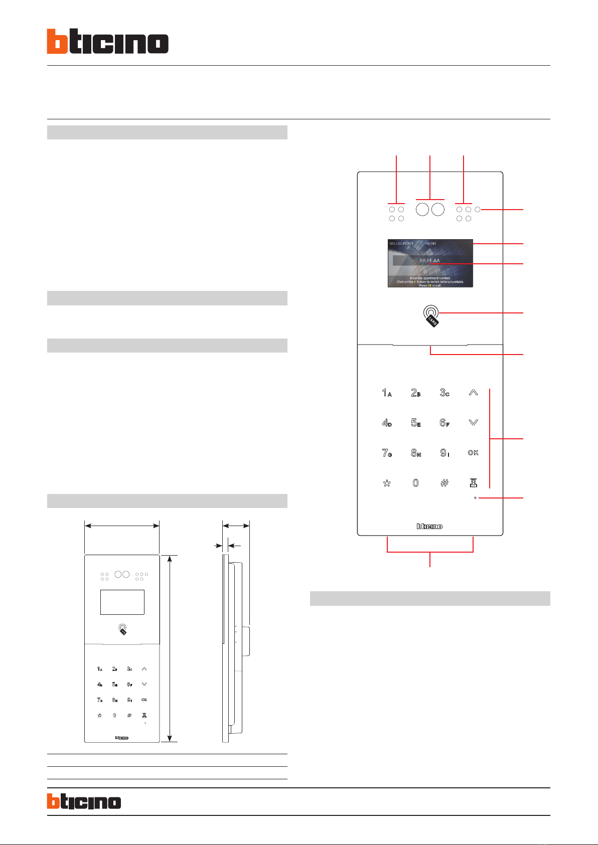
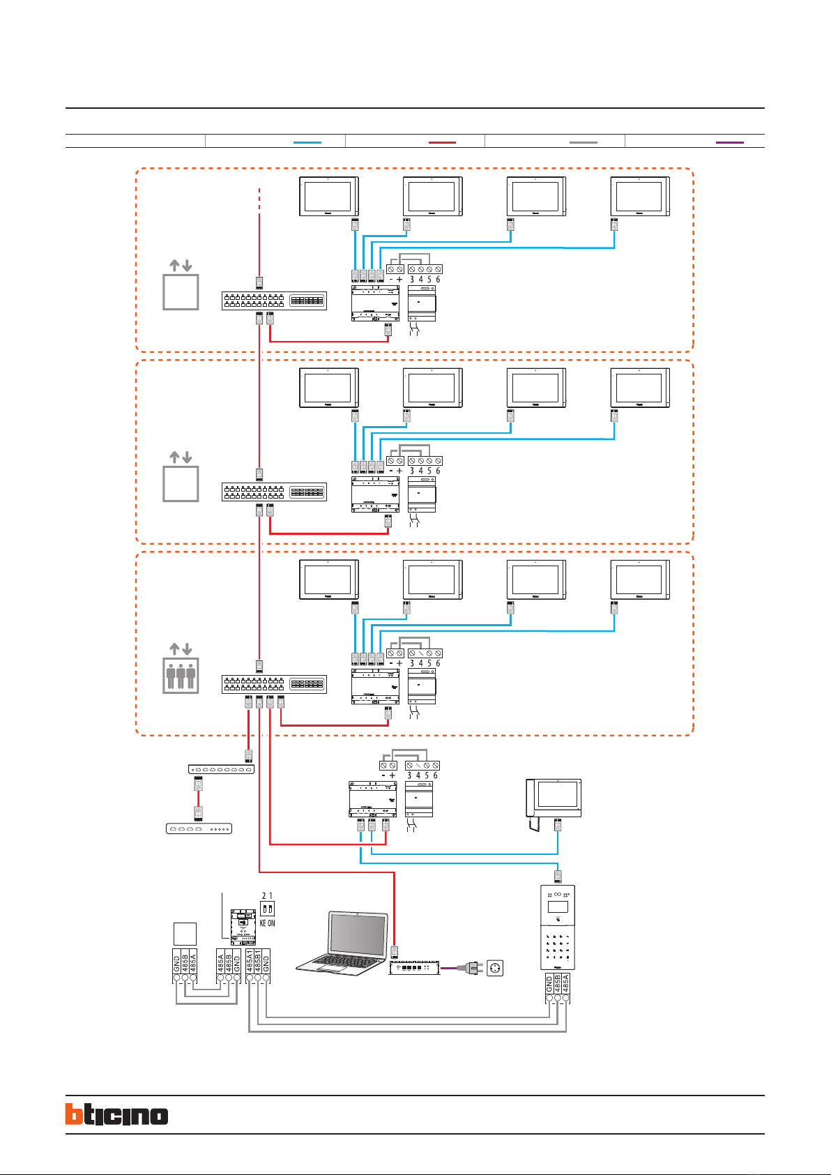
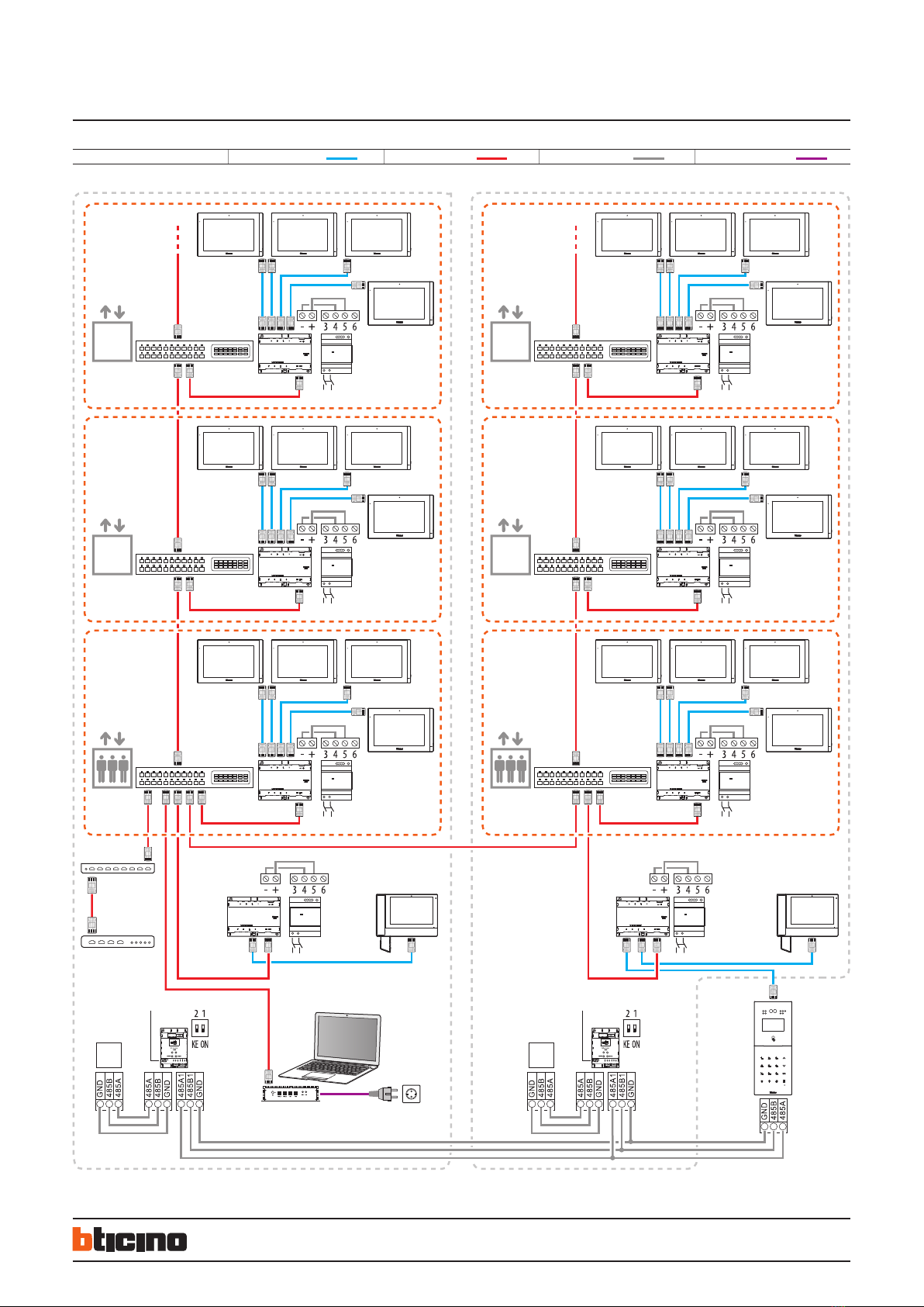
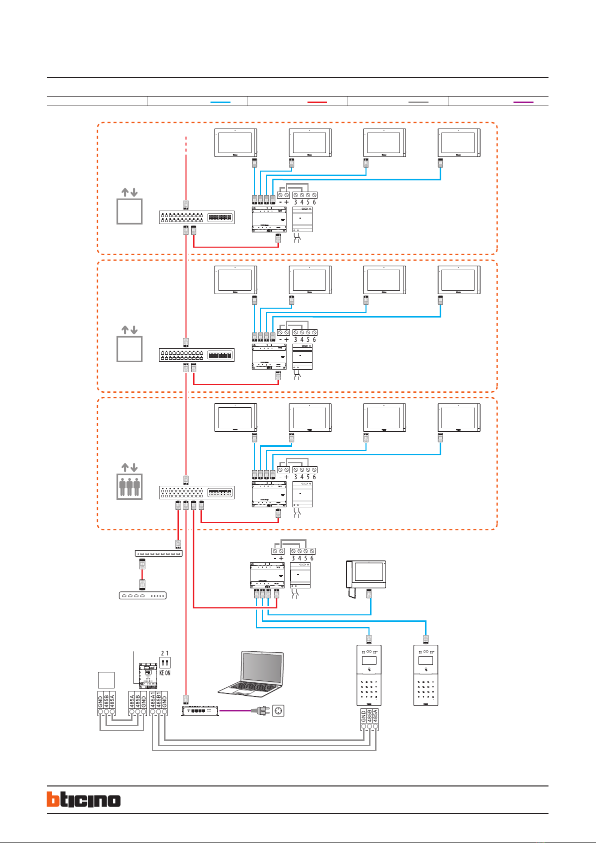
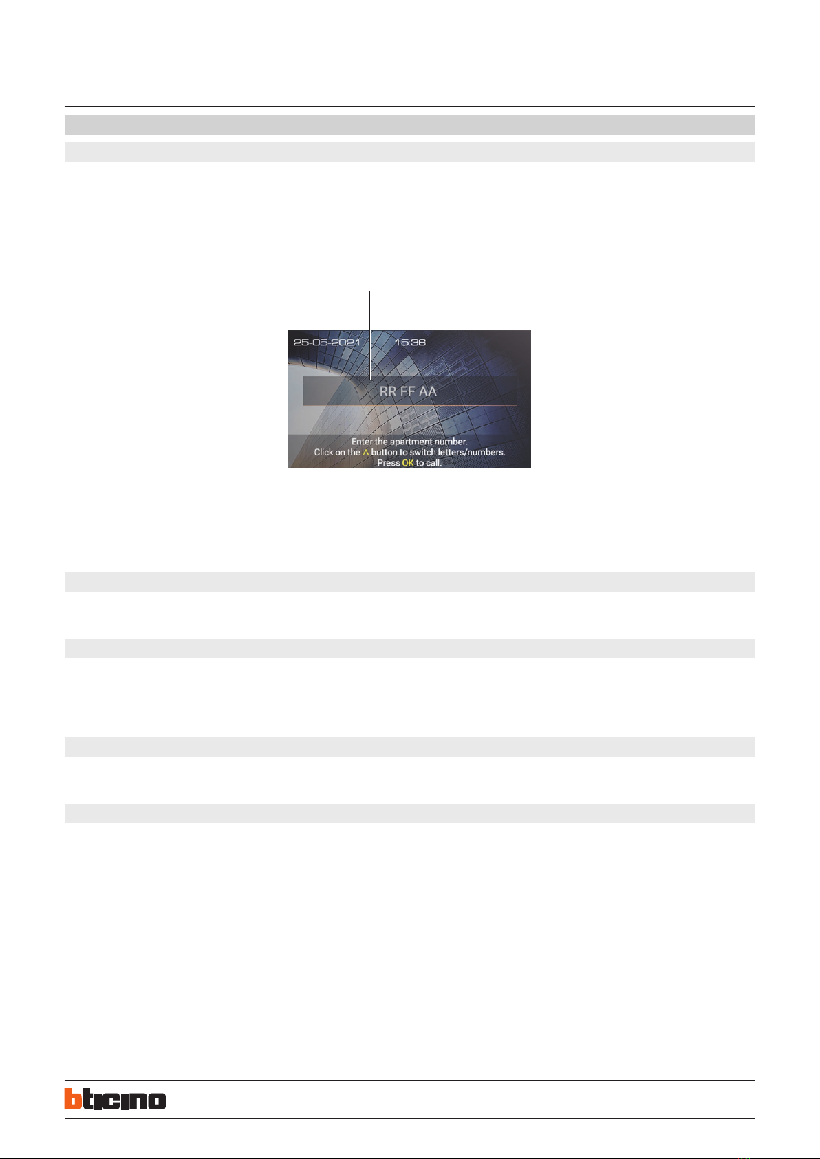
IP DES - Video entrance panel
with 4.3” display and keypad
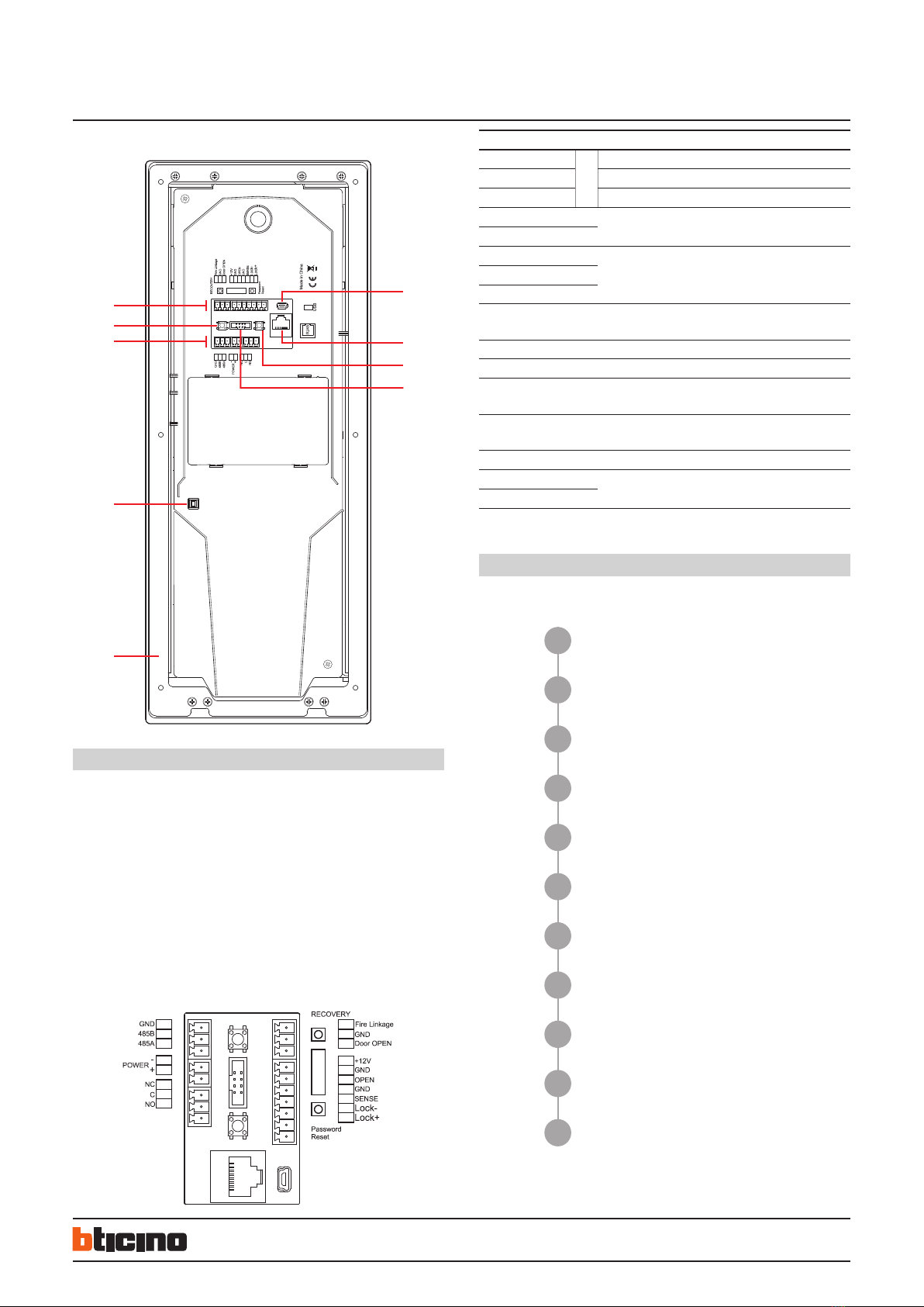
Rear view
Legend
1. Mounting bracket
2. Tamper switch
3. Connection clamp
4. Not used
5. USB Connector (not used)
6. RJ45 Connector (*)
7. Reset setting password and local access code
8. Not used
(*) This device does not support standard POE power supplies, but only POE
power supplies identified with item no. 375002. Connect the cat5/5e/6 FTP or
cat5/5e/6 UTP cable with ferrite supplied to the connector. The wrong wiring
of the Ethernet cable connecting the device to the Poe Switch 375002 could
damage the device itself. The RJ45 cable must be at least 200 mm long
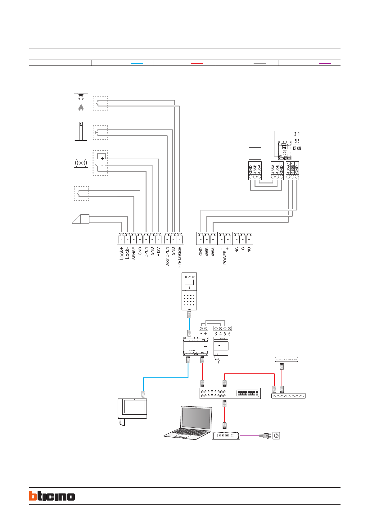
Connection clamps
GND
Lift Control
system common ground terminal for RS485 connection
RS485B terminal A
RS485A terminal B
-additional power supply clamps
+
NC
interlocked contactC
NO
FIRE Linkage – GND local door lock release pushbutton connection for
firealarm system
Door OPEN – GND local door lock release pushbutton connection
+12V – GND OPEN access control devices power supply
OPEN third party access control signal input for door lock
opening (+12Vdc pulse)
GND system common ground terminal for third party
connection
SENSE
door status signal input (dry contact)
LOCK+ electric door lock connection and control (12V - 4A
impulsive on 30 Ohm maximum)
LOCK-
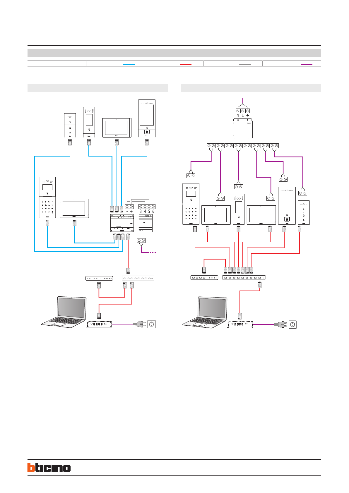
Configuration
To use the device, it is necessary to configure it and create the Community structure
using the IP DES System software, following the steps below:
For further information, please refer to the IP DES System Software Manual and Small
video entrance panel manual, available for download from
www.homesystems-legrandgroup.com website
Step
Step
Step
Step
Step Community customisation
Step
Step
Step
Step
Step
Step
Registration of the Community on the installer’s Cloud
Saving of passwords
CommunityVLAN network creation
Community structure definition
Community structure creation
Device MAC address registration
Forwarding of the address book to the DES Server
Installation of the devices
Activation of the devices
System test
01
02
03
04
05
06
07
08
09
10
11