4
Beschreibung
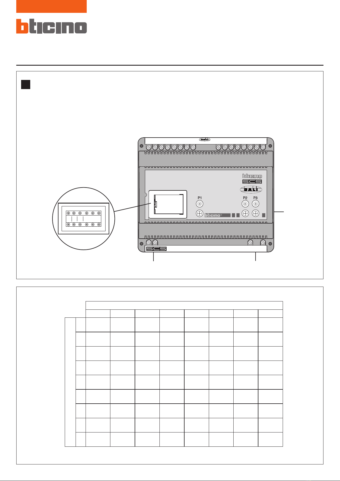
Die Schnittstelle SCS DALI Art. F429 ermöglicht es den BUS SCS mit den Vorrichtungen zu verbinden, die über das Protokoll DALI
gesteuert werden. So können dann die DALI Geräte über den BUS SCS geregelt werden. Die Vorrichtung ist mit 8 unabhängigen Ausgängen
ausgestattet an denen bis zu 16 DALI Geräte pro Ausgang geschlossen werden können. An dem Gerät befinden sich drei Tasten mit den
dazugehörenden drei Leds.
- P1 Gestattet es die Vorrichtung auf eine virtuelle Konfiguration zu schalten.
- P2 Ermöglicht es den Ausgang DALI zu wählen. Nach einem Druck blinkt die Led X-Mal, was der Nummer des gewählten Ports
entspricht. Durch einen erneuten Druck, wird der nächste Ausgang gewählt.
- P3 Schaltet die Stromlast zyklisch ein und aus. Durch längeres Drücken der Taste wird der Ausgang der mit P2 gewählt wurde, auf die
Dimmerschaltung eingestellt
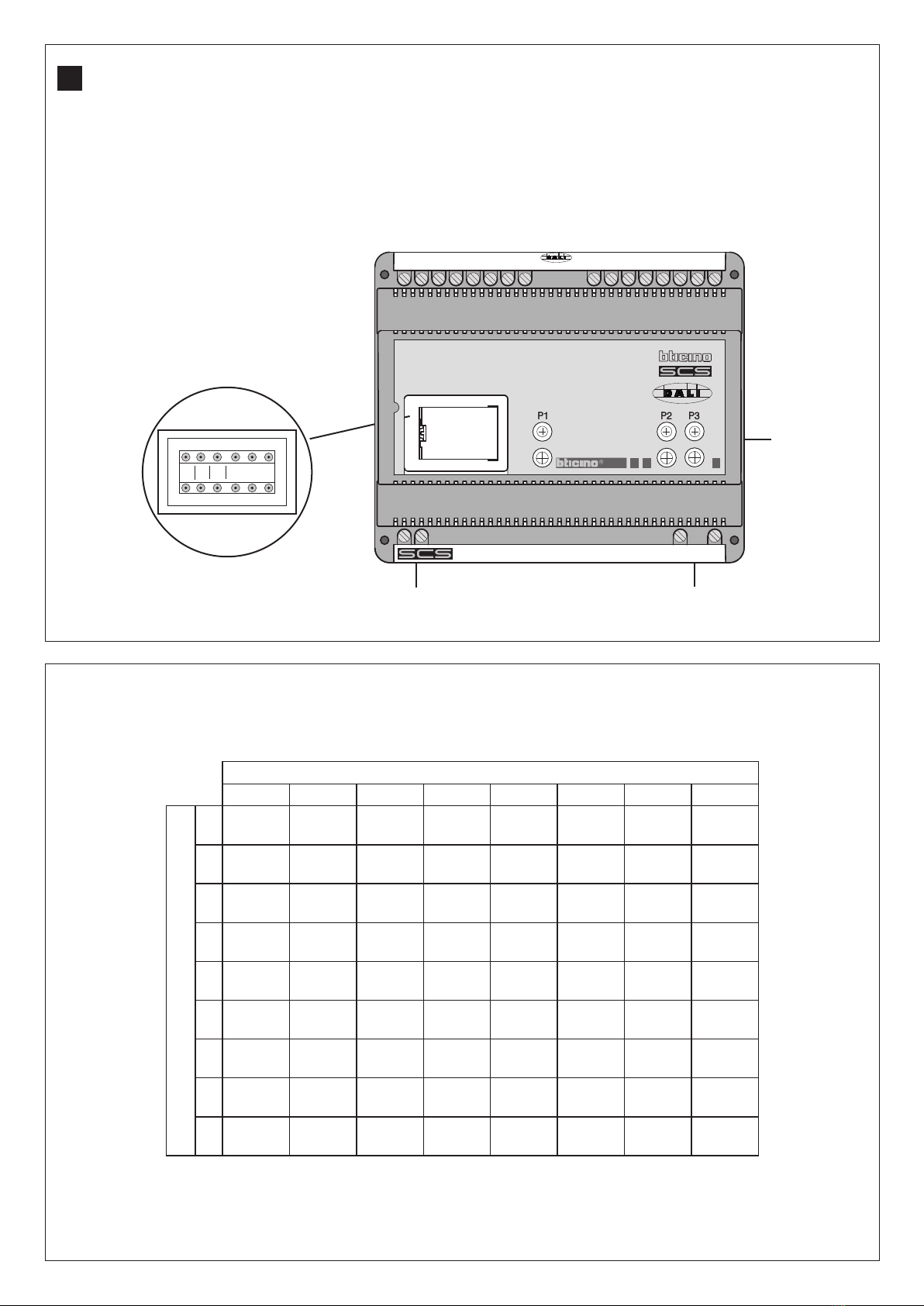
Technische Daten
• Speisung: 110-240V AC 50/60HZ
110-240V DC
• Max. Stromaufnahme: 5mA vom BUS SCS
• Betriebstemperatur: 5°C ÷ 45°C
• DALI Ausgänge: 8 unabhängige Ausgänge
gemäß IEC 60929
• DIN Module: 6
BUS
SCS
110-240V
Led
L
N
8
7
6
5_
+
_
+
_
+
_
+
4
3
2
1_
+
_
+
_
+
_
+
OUTPUT
AGM
5
AUSGANG
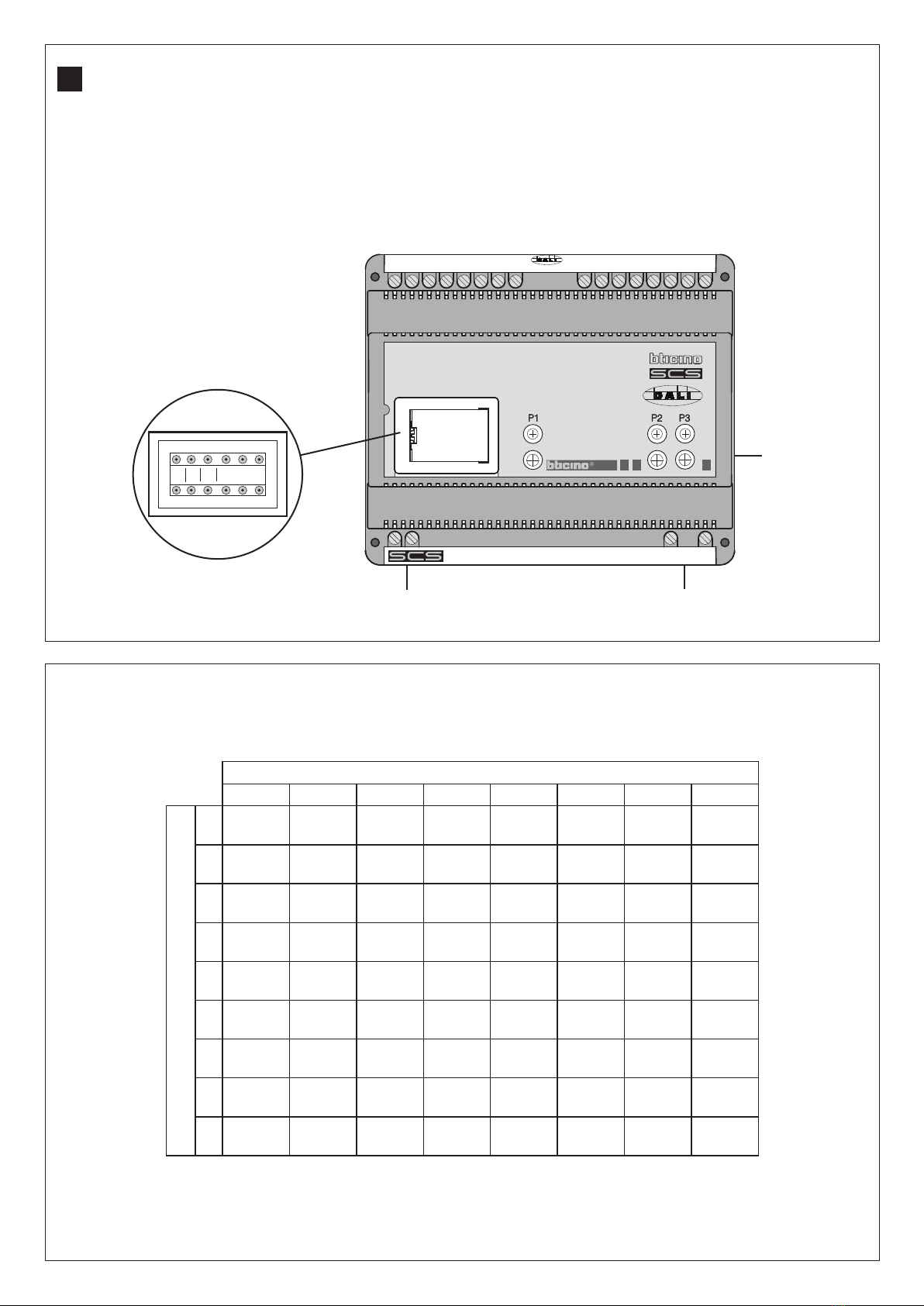
12345678
A=
1A=1
PL=1
A=1
PL=2
A=1
PL=3
A=1
PL=4
A=1
PL=5
A=1
PL=6
A=1
PL=7
A=1
PL=8
2A=2
PL=1
A=2
PL=2
A=2
PL=3
A=2
PL=4
A=2
PL=5
A=2
PL=6
A=2
PL=7
A=2
PL=8
3A=3
PL=1
A=3
PL=2
A=3
PL=3
A=3
PL=4
A=3
PL=5
A=3
PL=6
A=3
PL=7
A=3
PL=8
4A=4
PL=1
A=4
PL=2
A=4
PL=3
A=4
PL=4
A=4
PL=5
A=4
PL=6
A=4
PL=7
A=4
PL=8
5A=5
PL=1
A=5
PL=2
A=5
PL=3
A=5
PL=4
A=5
PL=5
A=5
PL=6
A=5
PL=7
A=5
PL=8
6A=6
PL=1
A=6
PL=2
A=6
PL=3
A=6
PL=4
A=6
PL=5
A=6
PL=6
A=6
PL=7
A=6
PL=8
7A=7
PL=1
A=7
PL=2
A=7
PL=3
A=7
PL=4
A=7
PL=5
A=7
PL=6
A=7
PL=7
A=7
PL=8
8A=8
PL=1
A=8
PL=2
A=8
PL=3
A=8
PL=4
A=8
PL=5
A=8
PL=6
A=8
PL=7
A=8
PL=8
9A=9
PL=1
A=9
PL=2
A=9
PL=3
A=9
PL=4
A=9
PL=5
A=9
PL=6
A=9
PL=7
A=9
PL=8
Je nach dem welcher Konfigurator in A eingesetzt ist, übernehmen die Ausgänge folgende Adresse:
N.B. Der Konfigurator PL ist nicht vorgesehen, da der Wert durch den Ausgang an den das DALI Gerät geschlossen ist, bestimmt wird. Alle Aus-
gänge gehören zu derselben Gruppe wie in G.
D