manuals.online logo
Brands
  1. Home
  2. •
  3. Brands
  4. •
  5. Bullard
  6. •
  7. Batteries Charger
  8. •
  9. Bullard Eclipse Powerhouse User manual

Bullard Eclipse Powerhouse User manual

Eclipse™Powerhouse™Charging Station
User Manual
www.bullard.com
The Powerhouse™ Charging Station is the perfect companion for your
Eclipse™ Thermal Imager. Designed to safely house and charge the Eclipse
and an accompanying battery, the Eclipse Powerhouse helps ensure that your
Eclipse will always be ready for action.
Using the Powerhouse as a free-standing
unit:
NOTE
Although the Powerhouse is designed for permanent vehicle installation,
Bullard also provides an optional AC adaptor kit for unattached,
free-standing use. As a free-standing unit, the Powerhouse cannot
provide secure storage of the thermal imager and its spare battery in
a vehicle in accordance with NFPA 1901-14.1.11.2. Free-standing use
is not recommended for vehicles. The adaptor kit includes an AC power
adaptor
Installation
The Powerhouse is designed to be mounted on any convenient flat-panel
surface in a vehicle. When installed and used in accordance with these
instructions, the unit is designed to comply with NFPA 1901-14.1.11.2 (see
caution for proper installation).
Location
Select a conveniently-located, flat-panel surface of sufficient size to
accommodate the unit. The unit can be conveniently mounted in any
orientation and will comply with NFPA 1901-14.1.11.2. The unit is secured to
the truck by means of two “L”-shaped aluminum
brackets. The brackets attach to the truck with
four (4) #10 stainless steel countersunk thread-
forming Phillips-head screws, which are provided.
The Powerhouse attaches to the same brackets
with four (4) #10 stainless steel Phillips-head pan
screws that are also provided with the unit (Figure 1).
Allow 5-inch clearance above to remove Eclipse.
Electrical Wiring
The unit is provided with a pair of wires for attachment to the power supply
in the vehicle. The wires are color-coded, with red signifying the positive (+)
conductor and black signifying the negative (-) conductor. Provide power to
the mounting location from a 5-Ampere fused uninterrupted power source
with a voltage of 12-24 VDC such as the apparatus battery. Securely fasten
the vehicle’s power supply wire to the matching positive or negative wire
from the Powerhouse using twist-on or crimp-style connectors. Consult an
electrician if you experience difficulty or require assistance.
NOTE
The Powerhouse should
be connected to an un-
switched circuit such as
the apparatus battery
that continues to provide
power when the vehicle
is not in use. Wiring the
Powerhouse to a switched
circuit or through a relay
may result in discharged
imager batteries if the
vehicle is left idle for
periods of more than a few
days at a time.
CAUTION
DO NOT wire the Powerhouse
to a third party apparatus
battery charger!
Failure to comply may result
in improper function of the
Powerhouse.
Marking and Drilling
the Panel
Print Figure 3 (located on the
back page of this manual) and
place the template in the desired
position in the truck. Mark the
locations of the four countersunk holes and electrical wire hole using the
template as a guide. Drill four (4) pilot holes using a #25 (0.1495”/3.75mm)
drill bit from which the Powerhouse brackets will hang. Also drill a suitably-
sized hole in the truck panel through which the Powerhouse wiring will pass,
ensuring that there are no sharp edges or burrs that could harm the wiring
insulation.
Mounting the Powerhouse
Once the five holes are drilled, attach the panel-mount brackets with four (4)
#10 stainless steel countersunk thread-forming Phillips-head screws that are
provided (Figure 4).
Figure 1
5” clearance
Figure 2
Figure 4
www.bullard.com
Preparing the Powerhouse unit for installation
First, make sure that the power is disconnected from the supply wiring. Next,
connect the positive power source wire securely to the red conductor located
on the back of the Powerhouse. Then connect the negative power source wire
securely to the black conductor located on the back of the Powerhouse. The
Powerhouse attaches to the same bracket with the four (4) #10 stainless
steel Phillips-head pan screws included in your installation kit (Figure 4).
You may have to press gently to compress the four rubber anti-vibration
pads on the bottom of the Powerhouse in order to properly seat the screws.
Installation is now complete. .
Operation
The Powerhouse charging station is designed to perform the following
functions:
• Securing the imager in the vehicle in accordance with NFPA 1901-14.1.11.2.
• Storing and recharging the battery in the imager and maintaining the
battery at full charge.
• Securing a spare rechargeable battery in accordance with NFPA 1901-
14.1.11.2.
• Storing and recharging the spare battery and maintaining it at full charge.
Inserting the Eclipse into the Powerhouse
NOTE
In order to store the Eclipse in the Powerhouse, a battery must be
installed in the camera. Without a battery installed, the gripper arms
will not automatically secure the camera properly. Therefore, storing a
camera without the battery installed can result in non-compliance with
NFPA 1901-14.1.11.2, if the arms are not manually closed.
Depress the “Bullard” button at the top of the Powerhouse to open the
gripper arms. For ease of use, the Eclipse should be oriented so that viewing
window is at the top and the lens is at the bottom, with the on/off switch and
“Bullard” facing the user (Figure 5). Set the imager firmly into place in the
Powerhouse. The gripper arms will close, and you will hear a “click” as the
unit locks into place. If in a noisy environment, gently pull on the camera to
ensure that the locking mechanism has engaged; otherwise, the camera will
not be properly secured and could pose a hazard in a moving vehicle. As an
additional indicator, the Powerhouse “Bullard” button will return to the non-
depressed position once the camera has been seated properly (Figure 6).
The battery charger is automatically activated when the imager is inserted.
Battery charge condition is indicated by the color of the light emitted by
the “Bullard” button. A pulsing red light indicates that the battery is being
charged; a solid green light indicates that the battery is fully charged and its
charge is being maintained by the Powerhouse unit.
NOTE
If the charging indicator light flashes between green and red for longer
than 15 minutes, your battery is damaged and should be disposed of
properly.
Removing the Eclipse from the Powerhouse
Depress the “Bullard” button at the top of the Powerhouse with your thumb
while grasping the imager with your hand. Once the camera has been
released by the gripper arms, the imager may be pulled away from the
Powerhouse unit.
Figure 5
Figure 6
Removing the Eclipse
Inserting the Eclipse
www.bullard.com
Eclipse™Powerhouse™Charging Station
User Manual
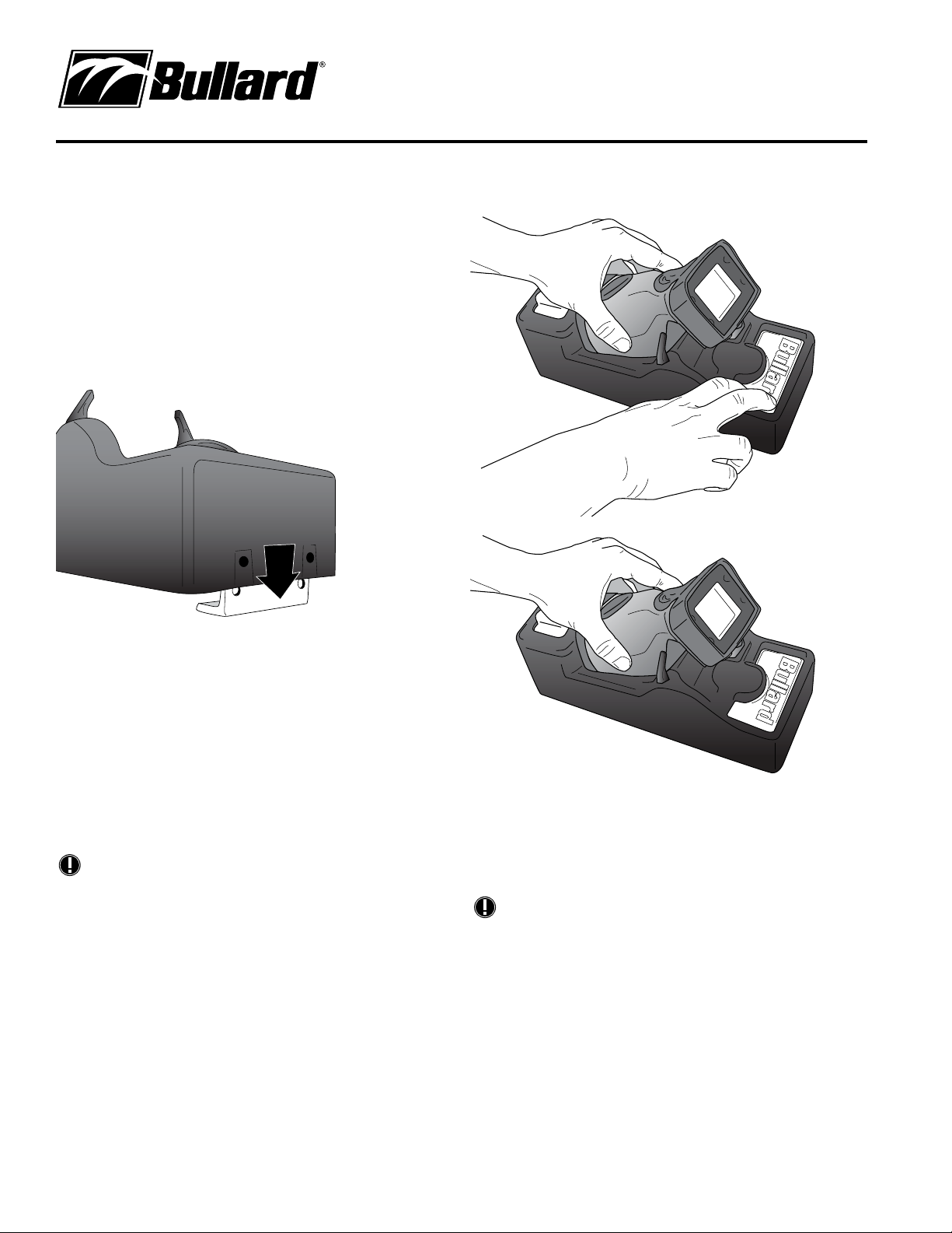
Inserting the spare rechargeable battery into the
Powerhouse
A spare battery charging port is located at the opposite end of the charging
station from the “Bullard” button. Align the battery’s molded grooves with
the grooves in the charger. Slide the latch to the open position with one hand
and insert the Eclipse battery into the charger with your other hand, releasing
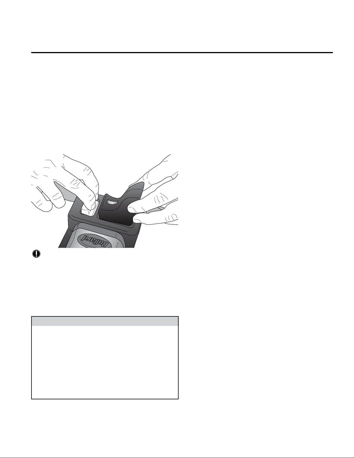
both when it locks (Figure 7). If the battery is inserted incorrectly, it will not
be possible to fully insert it. In this case, the battery will not snap into place,
and the charging circuit will not activate. Battery charge condition is indicated
by the color emitted by the sliding latch. A pulsing red light indicates that the
battery is being charged; a pulsing green light indicates that the battery is
fully charged and its charge is being maintained by the Powerhouse unit.
NOTE
If the charging indicator light flashes between green and red for longer
than 15 minutes, your battery is damaged and should be disposed of
properly.
Removing the spare rechargeable battery from the
Powerhouse
Slide the latch to the open position to release the battery. Lift the battery out
of the charger while holding the latch open.
Warranty
Bullard warrants to the original purchaser that the Powerhouse charging
station is free of defects in materials and workmanship under intended use
and service for a period of one year from date of manufacture. Bullard’s
obligation under this warranty is limited to repairing or replacing, at Bullard’s
option, articles that are returned within the warranty period and that, after
examination, are shown to Bullard’s satisfaction to be defective, subject to
the following limitations:
a) Article must be returned to Bullard with shipping charges prepaid.
b) Article must not be altered from its original configuration.
c) Articles must not have been misused, abused, or damaged in transport.
In no event shall Bullard be responsible for damages, loss of use, or other
indirect, incidental, consequential or special costs, expenses or damages
incurred by the purchaser, notwithstanding that Bullard has been advised of
the possibility of such damages.
Any implied warranties, including warranties of merchantability and fitness
for a particular purpose, are limited in duration to one year from the date of
manufacture of this product.
Some states do not allow the exclusion or limitation of incidental or
consequential damages, or allow limitations on how long an implied warranty
lasts, so the above limitations or exclusions may not apply to you. This
warranty gives you specific legal rights, and you may have other rights which
vary from state to state.
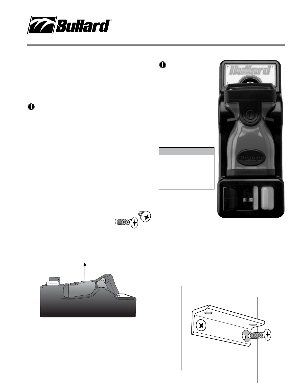
Figure 7
The Eclipse Powerhouse is compliant with NFPA 1901-14.1.11.2 and is
able to be mounted in any orientation. Please use caution when choosing
a mounting location so that, if the camera is accidentally dropped while
being installed in the Powerhouse, it will not injure anyone nearby. For this
reason, we do not recommend mounting the Powerhouse on the ceiling of
any vehicle.
Use only a fused power source of 5 amp capacity and 12-24 VDC voltage.
Ensure that the polarity of the power supply wiring is correct.
Failure to follow these instructions could result in serious injury or
malfunction of the unit.
CAUTION
©2015 Bullard. All rights reserved.
Eclipse and Powerhouse are trademarks of Bullard.
6050068840D (0815)
ISO 9001
certified
www.bullard.com
Americas:
Bullard
1898 Safety Way
Cynthiana, KY 41031-9303 • USA
Toll-free within USA: 877-BULLARD (285-5273)
Tel: +1-859-234-6616
Fax: +1-859-234-8987
Europe:
Bullard GmbH
Lilienthalstrasse 12
53424 Remagen • Germany
Tel: +49-2642 999980
Fax: +49-2642 9999829
Asia-Pacific:
Bullard Asia Pacific Pte. Ltd.
LHK Building
701, Sims Drive, #04-03
Singapore 387383
Tel: +65-6745-0556
Fax: +65-6745-5176

Other Bullard Batteries Charger manuals

Bullard POWERHOUSE User manual

Bullard

Bullard POWERHOUSE User manual

Bullard Eclipse User manual

Bullard

Bullard Eclipse User manual

Popular Batteries Charger manuals by other brands

Agilent Technologies E7002 reference guide

Agilent Technologies

Agilent Technologies E7002 reference guide

Teltonika TeltoCharge EVC131 installation manual

Teltonika

Teltonika TeltoCharge EVC131 installation manual

Humanscale NeatCharge Assembly instructions

Humanscale

Humanscale NeatCharge Assembly instructions

IKEA koppla manual

IKEA

IKEA koppla manual

Radio Shack AA Travel Charger Pack owner's manual

Radio Shack

Radio Shack AA Travel Charger Pack owner's manual

Coulomb Technologies ChargePoint CT500 installation guide

Coulomb Technologies

Coulomb Technologies ChargePoint CT500 installation guide

VOLTCRAFT 20 01 88 operating instructions

VOLTCRAFT

VOLTCRAFT 20 01 88 operating instructions

Hamron 608201 operating instructions

Hamron

Hamron 608201 operating instructions

Mec NOVA-150F Series instruction manual

Mec

Mec NOVA-150F Series instruction manual

Milwaukee M12B2 Operator's manual

Milwaukee

Milwaukee M12B2 Operator's manual

Vivanco ACS 9 operating instructions

Vivanco

Vivanco ACS 9 operating instructions

Calix BC 1207 manual

Calix

Calix BC 1207 manual

Horizon Hobby Kinexsis KX80 80W Quick programming guide

Horizon Hobby

Horizon Hobby Kinexsis KX80 80W Quick programming guide

Sterling Power Products BB1224120 Handbook

Sterling Power Products

Sterling Power Products BB1224120 Handbook

MOB THINNY WIRELESS user manual

MOB

MOB THINNY WIRELESS user manual

Stryten Energy M Series manual

Stryten Energy

Stryten Energy M Series manual

Vivo CART-LAPC1 instruction manual

Vivo

Vivo CART-LAPC1 instruction manual

LIPOWER C400L Series user manual

LIPOWER

LIPOWER C400L Series user manual

manuals.online logo
manuals.online logoBrands
  • About & Mission
  • Contact us
  • Privacy Policy
  • Terms and Conditions

Copyright 2025 Manuals.Online. All Rights Reserved.