Bullard MX Thermal Imager
Use and Operation
3
Use and Operation
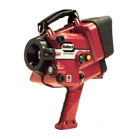
Power: To turn on your Bullard Thermal Imager, simply
depress the large green “On/Off”button on the left side of
the unit (Item 1, Figure 1). Upon depressing the “On/Off”
button, the “Sleep”indicator light will appear on the
viewing screen. However, the thermal image will not appear
immediately as the unit requires a few moments to
warm-up and complete the self-calibration process. After
approximately 15 seconds, the display screen will light up
and the camera will complete its self-calibration.
Once this boot-up process is complete, the thermal image
will appear on the screen. If the camera has been in recent
use, immediately prior to turning on, thermal stabilization
may not be required during the self-calibration process.
Therefore, as soon as the screen lights up, the thermal
image will appear.
Always use the power switch to turn the camera off. If the
battery is removed before the power is switched off, the
normal self-diagnostics could be interrupted and upon
reinsertion of the battery, the screen may not display a
thermal image. In this case, the camera must be switched
off using the power switch and rebooted by pressing the
power switch.
Sleep Mode: To conserve battery life, the BullardThermal
Imager includes a unique “Sleep”feature. To put the unit
into “Sleep”mode, simply press the yellow “Sleep”button
on the left side of the unit (Item 2, Figure 1). When in the
“Sleep”mode, the “Sleep”indicator light will appear on
the viewing screen. To bring the unit out of the “Sleep”
mode, simply push the yellow button again. The thermal
image will immediately reappear on the screen. The
“Sleep”mode disengages the transmitter, if activated.
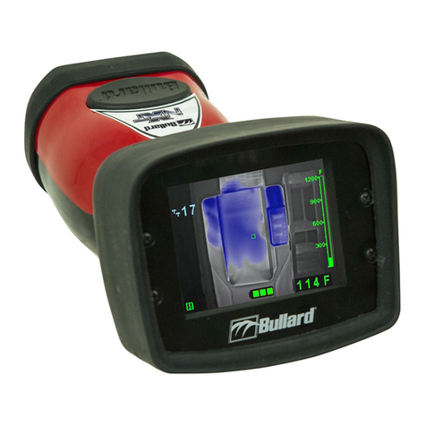
LED Low-Battery Warning Lights: Five LED lights
located to the left of the LCD screen indicate the life of the
battery in the thermal imager.The green LED light at the top
indicates a fully charged battery. As the battery begins to
discharge the lights will change to yellow and then red,
indicating the battery is low and should be taken out and
re-charged.
On-Screen Battery Status Indicators: The on-screen
battery display is located in the upper right-hand corner of
the LCD screen. This battery indicator resembles a small
battery and is green in color. When the battery icon
appears completely green this indicates that the thermal
imager battery is fully charged. As the battery in the
imager begins to discharge, the level of green color in the
battery icon will decrease. When the battery nears total
discharge, a warning triangle will begin to flash in the
middle of the screen indicating the need to change the
battery.
EI (Electronic Integration) Mode: The Bullard MX is
equipped with a state-of-the-art,
Automatic Thermal
Throttle
. The Bullard “smart”iris automatically manages
the level of thermal energy that reaches the sensor,
ensuring that the image on the screen is always as sharp
as possible, regardless of the level of heat the imager
detects. When the “smart”iris engages, the lettters EI will
appear on the screen just below the battery icon.
NOTE
You may observe a momentary freeze in the
image as the unit switches into or out of the
“smart”iris mode.
Red Hot Feature: To assist the operator in interpreting
the image on the screen, the Bullard MX comes standard
with the “
Red Hot”
feature. Once the “smart”iris activates
indicating increased thermal energy, the Bullard MX will
paint the hottest area in the view red. This feature only
operates in the EI mode.
Relative Heat Indicator (RHI): The Bullard MX
Thermal Imager is equipped with an on-screen “
Relative
Heat Indicator”(RHI)
. The RHI provides a relative
temperature for the object, or objects, framed in the
on-screen cursor. The relative temperature is then
displayed on the bar style gauge located on the right side
of the screen.The RHI will not register temperatures below
100°F or above 1,100°F. The accuracy of the indicated
temperatures is affected by many factors. For example, the
relative temperature displayed on the gauge is an average
of the surface temperatures of all objects targeted in the
cursor.
Additionally, the RHI is programmed to assume that all
objects exhibit an emissivity coefficient of 0.95. This
emissivity factor was chosen based on an average of the
most probable objects that would appear in a fire related
scene. However, some objects, especially those with shiny
silver surfaces, will exhibit very different emissivity factors
and thus adversely affect the accuracy of the RHI.
Therefore, operators should not use the RHI to try to
determine exact temperatures. This tool is best used to
provide a general idea of heat conditions and to compare
the relative heat of one object to that of another.
WARNING
The Relative Heat Indicator (RHI) cannot be relied on to
provide accurate temperature measurements. Making
tactical decisions based on the temperatures indicated
on the RHI scale could result in death or serious injury.


