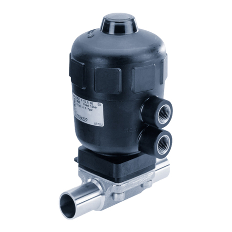
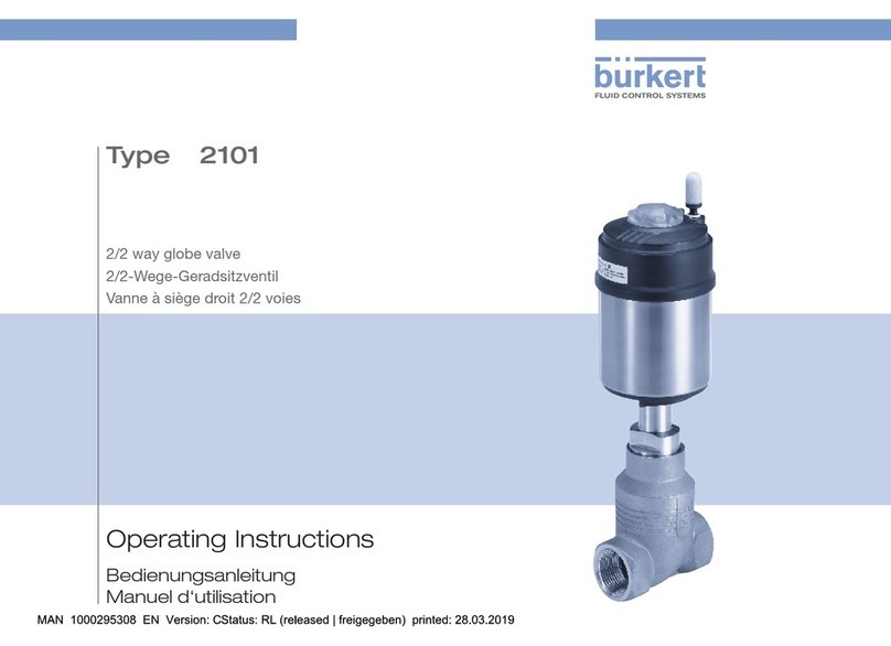
Burkert 2012 User manual

Operating Instructions
Bedienungsanleitung
Manuel d‘utilisation
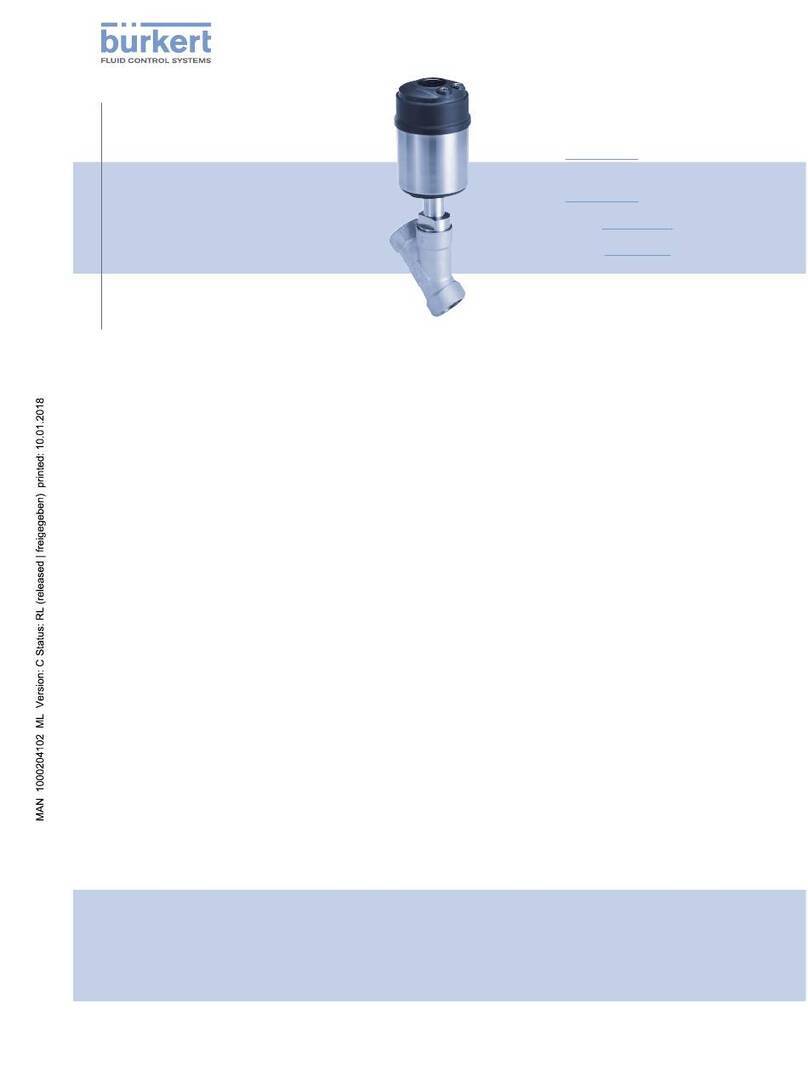
Type 2012
Globe control valve, pneumatically operated
Actuator sizes 40 mm - 125 mm, Nominal diameter DN10 - 65
Kolbengesteuertes Geradsitzventil
Antriebsgrößen 40 mm - 125 mm, Nennweiten DN10 - 65
Vanne à siège droit commandée par piston
Tailles d'actionneur 40 mm - 125 mm, Diamètre nominal DN10 - 65

We reserve the right to make technical changes without notice.
Technische Änderungen vorbehalten.
Sous réserve de modifications techniques.
© 2000 - 2021, Bürkert Werke GmbH & Co. KG
Operating Instructions 2104/23_EU-ML_00804072 / Original DE

3
1 OPERATING INSTRUCTIONS ................................................................4
1.1 Symbols ....................................................................................... 4
1.2 Definition of the term "device" ................................................ 4
2 INTENDED USE .............................................................................................5
3 BASIC SAFETY INSTRUCTIONS ..........................................................5
4 GENERAL NOTES.........................................................................................6
4.1 Contact addresses ................................................................... 6
4.2 Warranty ...................................................................................... 6
4.3 Information on the Internet ...................................................... 6
5 SYSTEM DESCRIPTION ............................................................................7
5.1 General description .................................................................. 7
6 STRUCTURE AND FUNCTION...............................................................7
6.1 Structure ...................................................................................... 7
6.2 Function ....................................................................................... 8
7 TECHNICAL DATA ........................................................................................9
7.1 Conformity ................................................................................... 9
7.2 Standards .................................................................................... 9
7.3 Type label ..................................................................................10
7.4 Operating conditions ..............................................................10
7.5 Control functions .....................................................................16
7.6 Mechanical data.......................................................................16
8 INSTALLATION ............................................................................................16
8.1 Safety instructions ...................................................................16
8.2 Before installation ....................................................................17
8.3 Installing valve body ................................................................17
8.4 Pneumatic connection ............................................................19
8.5 Disassembly..............................................................................20
9 MAINTENANCE, CLEANING ................................................................ 20
9.1 Safety instructions ...................................................................20
9.2 Maintenance work ...................................................................21
9.3 Changing the valve set ...........................................................21
10 FAULTS ........................................................................................................... 23
11 SPARE PARTS.............................................................................................23
11.1 Replacement part set .............................................................23
11.2 Overview of spare parts .........................................................24
12 TRANSPORTATION, STORAGE, DISPOSAL ................................ 24
Contents
Type 2012
English

4
Operating instructions
Type 2012
1 OPERATING INSTRUCTIONS
The operating instructions describe the entire life cycle of the device.
Keep these instructions in a location which is easily accessible to
every user and make them available to every new owner of the device.
Important safety information!
Failure to observe these instructions may result in hazardous
situations.
▶The operating instructions must be read and understood.
1.1 Symbols
DANGER!
Warns of an immediate danger!
▶Failure to observe these instructions will result in death or seri-
ous injuries.
WARNING!
Warns of a potentially hazardous situation!
▶Failure to observe these instructions may result in serious inju-
ries or death.
CAUTION!
Warns of a potential danger!
▶Failure to observe these instructions may result in moderate or
minor injuries.
NOTE!
Warns of damage!
▶Failure to observe these instructions may result in damage to
the device or the system.
Indicates important additional information, tips and
recommendations.
Refers to information in these operating instructions or in
other documentation.
▶Designates instructions to avoid a danger.
→Highlights a procedure which you must carry out.
1.2 Definition of the term "device"
The term "device" used in these instructions always refers to the
Type 2012 piston-operated globe valve.
In these instructions, the unit bar stands for relative pressure.
The absolute pressure is stated separately in bar (abs).
English

5
Intended use
Type 2012
2 INTENDED USE
Improper use of Type 2012 may be hazardous to persons,
systems in the vicinity and the environment.
▶The device is designed to control the flow of liquid and gaseous
media.
▶In potentially explosive environments, the device must only be used
in accordance with the specifications on the separate Ex-type
label. The additional information and safety instructions relating
to Ex areas enclosed with the device must be adhered to when
deploying the device.
▶Devices without a separate Ex-type label must not be used in
potentially explosive areas. Note the permissible data, operating
and usage conditions specified in the contract documentation and
operating instructions. These are described in Chapter „Technical
data“.
▶Use the device only in conjunction with third-party devices and
components recommended or approved by Bürkert.
▶Prerequisites for safe and trouble-free operation are correct trans-
port, correct storage and installation as well as careful operation
and maintenance.
▶Use the device only as intended.
3 BASIC SAFETY
INSTRUCTIONS
These safety instructions do not take account of any:
• Contingencies or events which may occur during installation, ope-
ration and maintenance of the devices.
• Local safety regulations that are within the operator’s scope of
responsibility, including those relating to the installation personnel.
High pressure danger!
▶Before loosening lines or valves, switch off the pressure and
bleed the lines.
Danger due to electric voltage.
▶Before accessing the device or the system , switch off the power
supply and secure it to prevent reactivation!
▶Observe the applicable accident prevention regulations and safety
regulations for electrical devices.
Risk of injury when opening the actuator.
The actuator contains a spring under tension. The spring that ejects
when the actuator opens may cause injuries.
▶Do not open the actuator.
Risk of injury due to moving parts in the device.
▶Do not reach into openings.
English

6
General notes
Type 2012
Risk of burns.
The device surface can become hot during continuous operation.
▶Do not touch the device with your bare hands.
General hazardous situations.
To prevent injuries, ensure that:
▶The system cannot be activated unintentionally.
▶Installation and maintenance may be performed by authorised
technicians only and with the appropriate tools.
▶The process must be restarted in a defined or controlled manner
after an interruption in the power supply or pneumatic supply.
▶Device may be operated only when in perfect condition and in
consideration of the operating instructions.
▶The general rules of technology must be followed for application
planning and operation of the device.
Please observe the following in order to protect against damage
to the device:
▶Feed only those media listed in chapter „7 Technical data“ into
the medium ports.
▶Do not place the valve under mechanical stress (e.g. by placing
objects on it or standing on it).
▶Do not make any external modifications to the valves.
▶Do not paint housing parts or screws.
4 GENERAL NOTES
4.1 Contact addresses
Germany
Bürkert Fluid Control Systems
Sales Centre
Christian-Bürkert-Str. 13–17
D-74653 Ingelfingen
Tel. +49 (0) 7940 - 10 91 111
Fax +49 (0) 7940 - 10 91 448
E-mail: [email protected]
International
The contact addresses can be found on the back pages of the printed
operating instructions.
They are also available online at: www.burkert.com
4.2 Warranty
A precondition for the warranty is that the Type 2012 globe valve is
used as intended in consideration of the specified operating conditions.
4.3 Information on the Internet
Operating instructions and data sheets for Type 2012 can be found
online at: country.burkert.com
English
7
System description
Type 2012
5 SYSTEM DESCRIPTION
5.1 General description
The 2/2-way globe valve Type 2012 is suitable for liquid and gaseous
media. Using neutral gases or air (control media), it controls the flow
of water, alcohol, oil, fuel, hydraulic fluid, saline solution, lye, organic
solvents and vapour (flow media).
One special characteristic of the globe valves are screwed-in seats,
which can be replaced when needed.
5.1.1 Restrictions
WARNING!
Risk of injury from pressure surge!
A pressure surge could cause lines and the device to burst. Because
of the risk of pressure surge, valves with the flow direction above
the seat must not be used for fluid media.
▶Observe the type of flow and type of medium for operating the
device.
6 STRUCTURE AND FUNCTION
6.1 Structure
The globe valve consists of a pneumatically actuated piston actuator
and a 2-way globe valve body.
The actuator is made from PA, or PPS for special operating conditions.
The self-adjusting packing gland guarantees a high degree of tightness.
The stainless steel valve body facilitates high flow values.
Transparent cap with
position indicator Actuator cover
Actuator housing
Pilot air ports
Actuator/body
interface with wrench
flat Globe body
Port connection
Fig. 1: Type 2012 globe valve, structure and description
English

8
Structure and function
Type 2012
6.2 Function
Depending on the variant, the valve seat is closed in the direction of
or against the medium flow.
Spring force (CFA) or pneumatic pilot pressure (CFB and CFI) generate
the closing force on the swivel plate. A spindle connected to the
actuator piston transmits the force.
6.2.1 Control functions (CF)
WARNING!
For control function I – risk of pilot pressure failure.
With control function I, the control unit and reset are pneumatic. No
defined position is reached during a pressure failure.
▶To ensure a controlled restart of the device, first apply pilot pressure
and then activate the medium.
A
(CFA)
P
A
Closed by spring force in rest
position
B
(CFB)
P
B
Opened by spring force in rest
position
I (CFI)
P
A
Actuating function via reciprocal
pressurisation
6.2.2 Flow direction below seat
Depending on the variant, the valve is closed against the medium flow
either with spring force (control function A, CFA) or pilot pressure
(control function B or I, CFB or CFI).
Because the medium pressure is below the swivel plate, it helps open
the valve.
WARNING!
Valve leak if there is too little minimum pilot pressure or high
medium pressure.
Minimum pilot pressure for CFB and CFI that is too low, or failing
to meet the permitted medium pressure, can cause a leak in the
valve seat.
▶Adhere to minimum pilot pressure.
▶Do not exceed the medium pressure.
▶See chapter „7.4.2 Pressure ranges“.
CFA SFB/SFI
Flow direction
1 2
Marking on the
housing
Fig. 2: Flow direction below seat (closing against medium)
English

9
Technical data
Type 2012
6.2.3 Flow direction above the seat
The valve is closed with the medium flow via spring force (control
function A, CFA). Because the medium pressure is above the swivel
plate, it helps the valve close and also contributes to sealing the
valve seat.
The valve opens via pilot pressure.
WARNING!
Risk of injury from pressure surge.
A pressure surge could cause lines and the device to burst. Because
of the risk of pressure surge, valves with the flow direction above
the seat must not be used for fluid media.
▶Observe the type of flow and type of medium for operating the
device.
In order to ensure complete opening, the minimum pilot
pressure must be applied!
Flow direction
Marking on the
housing
1 2
Fig. 3: Flow direction above the seat (closing with the medium)
7 TECHNICAL DATA
7.1 Conformity
The Type 2012 globe valve conforms to the EU Directives as per the
EU Declaration of Conformity.
7.2 Standards
The applied standards as used to verify compliance with the EU Direc-
tives can be found in the EC type examination certificate and/or the
EC Declaration of Conformity.
According to Pressure Equipment Directive observe the following
operating conditions:
DN Maximum pressure for compressible fluids
of Group 1 (dangerous gases and vapours
according to Art. 3, No. 1.3, letter a, first
dash)
DN65 15 bar
English

10
Technical data
Type 2012
7.3 Type label
2012 A PTFE Kv31
PS 10bar
Tmed -10 - +180 °C
see manual for derating
00266857
W17AL
Flow 1 2
Made in Germany
Order number
Flow direction
Manufacture code (coded)
For derating, please
refer to the ope-
rating instructions.
2012 A PTFE Kv31
PS 10bar
Tmed -10 - +180 °C
see manual for derating
00266857
W17AL
Flow 1 2
Made in Germany
2012 A PTFE Kv31
PS 10bar
Tmed -10 - +180 °C
see manual for derating
00266857
W17AL
Flow 1 2
Made in Germany
Type
Medium temperature
Control function
Medium pressure
Seal material
Flow coefficient
Fig. 4: Type label description (example)
7.4 Operating conditions
7.4.1 Temperature ranges
Actuator
size [mm]
Actuator
material
Temperature range
Medium (for PTFE
and PEEK seal)
Environment 1)
40–63 PA –10 – see „Fig. 5“ –10 –see „Fig. 5“
80–125 PA –10 – +180 °C –10 – +60 °C
40–80 PPS –10 – +230 °C +5 – +140 °C
100–125 PPS –10 – +230 °C +5 – +90 °C
short-term up to
max. +140 °C
Tab. 1: Temperature ranges
1) When using a pilot valve the max. ambient temperature is
+55 °C.
Medium
temperature [°C]
Ambient tem-
perature
[°C]
100 120 140 160 180 200
70
60
50
40
30
20
∅ 63
∅ 50
∅ 40
Fig. 5: Temperature range of maximum medium and ambient temperature
for PA actuators
English

11
Technical data
Type 2012
7.4.2 Pressure ranges
Actuator
material
Actuator size [mm] Max. Pilot pressure
[bar]
PA 40–100 10
125 7
PPS 40–80 10
100–125 7
Tab. 2: Maximum pilot pressure
Medium pressure and pilot pressure for control function A, flow
direction below seat (standard):
DN
Maximum medium pressure/minimum pilot pressure
Actuator size ø [mm]
40 50 63 80 100 125
10/15 15/4.0 16/4.1 25/4.5
20 6.5/4.0 11/4.1 16/4.5 25/5.0
25 5.2/4.1 11/4.5 25/5.0
32 6/4.5 14/5.0 16/4.4 25/3.2
40 4/4.5 9/5.0 12.5/4.4 25/4.1
50 2.5/4.5 6/5.0 7.2/4.4 24/5.7
65 12/5.6
Tab. 3: Medium and pilot pressure CFA, standard
Derating pressure and temperature ranges
Usage limits of the valve (derating medium pressure)
Temperature Medium pressure
–10 – +50 °C 25 bar
100 °C 24.5 bar
150 °C 22.4 bar
200 °C 20.3 bar
230 °C 19 bar
Tab. 4: Derating the medium pressure as per DIN EN 12516-1/
PN25
Temperature Medium pressure
–29 – +38 °C 19 bar
50 °C 18.4 bar
100 °C 16.2 bar
150 °C 14.8 bar
200 °C 13.7 bar
230 °C 12.7 bar
Tab. 5: Derating the medium pressure as per ASME B16.5/
ASME B16.34 Cl.150
English

12
Technical data
Type 2012
Temperature Medium pressure
–10 – +50 °C 14 bar
100 °C 14 bar
150 °C 13.4 bar
200 °C 12.4 bar
230 °C 11.7 bar
Tab. 6: Derating the medium pressure as per JIS B 2220 10K
Usage limits of medium and ambient temperature
Ambient temperature [°C]
0 20 40 60 80 100 120 140 160 180 200 220
50
60
90
80
70
140
130
120
110
100
Medium temperature [°C]
Fig. 6: Derating CLASSIC ANTG40
Ambient temperature [°C]
0 20 40 60 80 100 120 140 160 180 200 220
50
60
90
80
70
140
130
120
110
100
Medium temperature [°C]
Fig. 7: Derating CLASSIC ANTG50, 63, 80
0 20 40 60 80 100 120 140 160 180 200 220
50
60
110
100
90
80
70
Medium temperature [°C]
Ambient temperature [°C]
Fig. 8: Derating CLASSIC ANTG 100, 125
English

13
Technical data
Type 2012
Required minimum pilot pressure depending on the medium
pressure
In the following graphs the required minimum control pressure is
shown for control functions A, B and I depending on the medium
pressure.
Control function A, flow direction above the seat
Pilot pressure [bar]
Medium pressure [bar]
Fig. 9: Pressure diagram, actuator ø 40 mm, control function A, flow
direction above the seat
Pilot pressure [bar]
Medium pressure [bar]
Fig. 10: Pressure diagram, actuator ø 50 mm, control function A, flow
direction above the seat
Pilot pressure [bar]
Medium pressure [bar]
Fig. 11: Pressure diagram, actuator ø 63 mm, control function A, flow
direction above the seat
English

14
Technical data
Type 2012
Medium pressure [bar]
Pilot pressure [bar]
Fig. 12: Pressure diagram, actuator ø 80 mm, control function A, flow
direction above the seat
Medium pressure [bar]
Pilot pressure [bar]
*
Fig. 13: Pressure diagram, actuator ø 100 mm, control function A, flow
direction above the seat
Medium pressure [bar]
Pilot pressure [bar]
Fig. 14: Pressure diagram, actuator ø 125 mm, control function A, flow
direction above the seat
* Medium pressure max. 15 bar according to Pressure Equipment Directive
2014/68/EU for compressible fluids of Group 1 (dangerous gases and
vapours according to Art. 4, paragraph (1) c) i) first dash).
English

15
Technical data
Type 2012
Control function B and I, flow direction below seat
0HGLXPSUHVVXUH>EDU@
3LORWSUHVVXUH>EDU@
DN15
DN40
DN50
ø 63
SFB/SFI
DN20
DN25
DN32
Fig. 15: Pressure diagram, actuator ø 63 mm, control function B and I, flow
direction below seat
0HGLXPSUHVVXUH>EDU@
3LORWSUHVVXUH>EDU@
DN25
ø 80
SFB/SFI
DN32
DN40
DN50
DN65
Fig. 16: Pressure diagram, actuator ø 80 mm, control function B and I, flow
direction below seat
0HGLXPSUHVVXUH>EDU@
3LORWSUHVVXUH>EDU@
ø 100
SFB/SFI
DN32
DN50
DN40
Fig. 17: Pressure diagram, actuator ø 100 mm, control function B and I, flow
direction below seat
0HGLXPSUHVVXUH>EDU@
3LORWSUHVVXUH>EDU@
ø 125
SFB/SFI
DN100
DN40
DN65
DN50
DN80
Fig. 18: Pressure diagram, actuator ø 125 mm, control function B and I, flow
direction below seat
English

16
Installation
Type 2012
7.4.3 Media
Control media Neutral gases, air
Flow media Water, alcohols, oils, fuels, saline solutions,
lyes, organic solvents, vapour
7.5 Control functions
Control function A Closed by spring force in rest position
Control function B Opened by spring force in rest position
Control function I Actuating function via reciprocal
pressurisation
7.6 Mechanical data
Materials
Valve body Stainless steel 316L
Actuator PA, PPS
Seal materials PTFE
(NBR, FKM, EPDM and PEEK on request)
Packing gland PTFE (carbon-filled)
8 INSTALLATION
8.1 Safety instructions
DANGER!
Risk of injury from high pressure in the system.
▶Before loosening lines and valves, turn off the pressure and vent
the lines.
WARNING!
Risk of injury due to improper installation.
▶Installation may be carried out by authorised technicians only and
with the appropriate tools!
Risk of injury due to unintentional activation of the system
and uncontrolled restart.
▶Secure the system against unintentional activation.
▶Following installation, ensure a controlled restart.
For control function I – risk of pilot pressure failure.
With control function I, the control unit and reset are pneumatic. No
defined position is reached during a pressure failure.
▶To ensure a controlled restart of the device, first apply pilot pressure
and then activate the medium.
Risk of injury due to moving parts in the device.
▶Do not reach into openings.
English

17
Installation
Type 2012
8.2 Before installation
Installation position: any, preferably actuator on top.
→Ensure that pipelines are aligned before connecting the valve.
→Note flow direction.
8.2.1 Preparatory work
→Clear impurities from pipelines (sealants, metal chips, etc.).
Devices with welded connection
Remove the actuator from the valve body:
→Clamp valve body into a holding device.
NOTE!
Damage to the seat seal or seat contour!
▶When removing the actuator, the valve must be in the open
position.
→For control function A:
Pressurise pilot air port with compressed air (6 bar): Valve
opens.
→Place a suitable open-end wrench on the wrench flat of the nipple.
→Unscrew actuator from the valve body.
8.3 Installing valve body
WARNING!
Risk of injury due to improper operation.
Failure to observe the tightening torque value is dangerous due to
the risk of damage to the device.
▶Use an open-end wrench for installation, never a pipe wrench.
▶Observe tightening torque (see „Tab. 7: Tightening torques
valve body/nipple“).
Dirt trap for devices with approval according to DIN EN 161
According to DIN EN 161 "Automatic shut-off valves for gas burners
and gas appliances", a dirt trap, which prevents the penetration of a
1 mm test pin, must be installed upstream of the valve.
→If the approval also applies to the stainless steel valve body, such
a dirt trap must be attached in front of the globe valve.
8.3.1 Installing the body
Welded connection
→Weld or bond valve body in pipeline system.
Other bodies
→Connect valve body to pipeline.
English

18
Installation
Type 2012
8.3.2 Install actuator (welded connection)
Seal
Fig. 19: Seal
→Check seal and replace if required.
WARNING!
Risk due to incorrect lubricants.
Unsuitable lubricant may contaminate the medium. There is a risk
of explosion in oxygen applications.
▶Only used accordingly approved lubricants for specific
applications.
→Before re-installation, grease nipple thread of the actuator (e.g.
using Klüberpaste UH1 96-402 from Klüber).
NOTE!
Damage to the seat seal or seat contour!
▶When installing the actuator, the valve must be in the open
position.
→For control function A:
Apply compressed air to the lower pilot air port (6 bar) so that
the swivel plate lifts up from the valve seat and is not damaged
during the screw-in process.
→Screw actuator into the valve body.
Tightening torques valve body/nipple
DN Tightening torques [Nm]
15 45 ± 3
20 50 ± 3
25 60 ± 3
32 65 ± 3
40 65 ± 3
50 70 ± 3
65 70 ± 3
Tab. 7: Tightening torques valve body/nipple
8.3.3 Turning actuator
The position of the ports can be seamlessly aligned by turning the
actuator 360°.
NOTE!
Damage to the seat seal or seat contour.
▶When turning the actuator, the valve must be in the open
position.
→Clamp valve body in a holding device (only for valves which have
not yet been installed).
English

19
Installation
Type 2012
→For control function A pressurise the pilot air port with compressed
air (6 bar): Valve opens.
→Counter with a suitable open-end wrench on the wrench flat of
the nipple.
→Place a suitable open-end wrench on the hexagon head of the
actuator.
WARNING!
Risk of injury from discharge of pressure and escaping medium.
The body connection can loosen when rotated incorrectly.
▶Only turn the actuator in the specified direction (see „Fig.
20“).
→Move the actuator into the required position by turning it clockwise
(seen from above).
Open-end wrench
Fig. 20: Rotating with open-end wrench
8.4 Pneumatic connection
DANGER!
Risk of injury from high pressure in the system.
▶Before loosening lines and valves, turn off the pressure and vent
the lines.
WARNING!
Risk of injury due to unsuitable connection hoses.
Hoses that cannot withstand the pressure and temperature range
can cause hazardous situations.
▶Only use hoses that are permitted for the specified pressure and
temperature range.
▶Note the data sheet information from the hose manufacturers.
For control function I – risk of pilot pressure failure.
With control function I, the control unit and reset are pneumatic. No
defined position is reached during a pressure failure.
▶To ensure a controlled restart of the device, first apply pilot pressure
and then activate the medium.
If the position of the pilot air ports is unfavourable for installing
the hoses, these can be seamlessly aligned by rotating the
actuator by 360°.
Control function A
→Connect control medium to bottom pilot air port of the actuator.
Control function B
English

20
Maintenance, cleaning
Type 2012
→Connect control medium to top pilot air port of the actuator.
Control function I
→Connect control medium to top and bottom pilot air port of the
actuator.
For usage in an aggressive environment, we recommend
using a pneumatic hose to drain all free pneumatic ports in
a neutral atmosphere.
Pilot air hose
Pilot air hoses of sizes 6/4 mm or ¼" can be used.
8.5 Disassembly
DANGER!
Risk of injury from discharge of pressure and escaping medium.
Dismantling a device which is under pressure is hazardous due to a
sudden discharge of pressure or escaping medium.
▶Before disassembly, shut off the pressure and vent all lines.
→Disconnect the pneumatic connection.
→Disassemble the device.
9 MAINTENANCE, CLEANING
9.1 Safety instructions
DANGER!
Risk of injury from high pressure in the system.
▶Before loosening lines and valves, turn off the pressure and vent
the lines.
Risk of injury due to electric shock.
▶Before reaching into the system, switch off the power supply and
secure against reactivation!
▶Observe the applicable accident prevention and safety regulati-
ons for electrical devices!
WARNING!
Risk of injury due to improper maintenance work.
▶Maintenance may be carried out by authorised technicians only.
▶Use an open-end wrench, never a pipe wrench, to screw the valve
body or actuator in or out, and observe the tightening torque.
Risk of injury due to unintentional activation of the system
and uncontrolled restart.
▶Secure the system against unintentional activation.
▶Following maintenance, ensure a controlled restart.
English
Other manuals for 2012
2
This manual suits for next models
9
Table of contents
Other Burkert Control Unit manuals

Burkert
Burkert 6012 User manual

Burkert
Burkert 6211 EV User manual

Burkert
Burkert 2012 User manual

Burkert
Burkert 2301 Series User manual

Burkert
Burkert 3364 User manual

Burkert
Burkert 2503 User manual

Burkert
Burkert 0283 User manual

Burkert
Burkert 6012 User manual

Burkert
Burkert 1134 User manual

Burkert
Burkert 2065 User manual

Burkert
Burkert 2832 User manual

Burkert
Burkert 2651 User manual

Burkert
Burkert 3232 User manual

Burkert
Burkert 8695 User manual

Burkert
Burkert 2101 User manual

Burkert
Burkert 8631 User manual

Burkert
Burkert 5411 User manual

Burkert
Burkert 2064 User manual

Burkert
Burkert 6022 User manual

Burkert
Burkert 0262 User manual