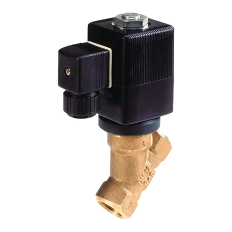
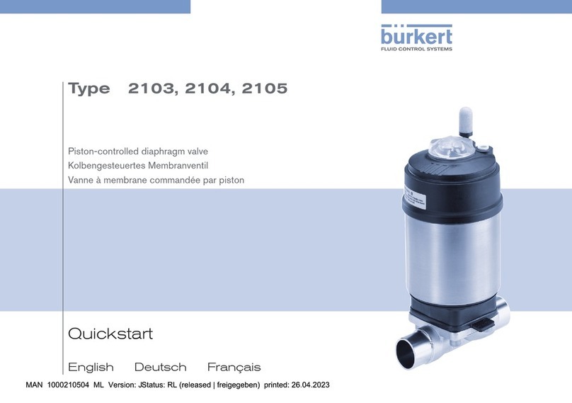
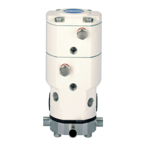
Burkert 2006 User manual

Quickstart
English Deutsch Français
Type 2006
3/2 way globe valve
3/2-Wege-Geradsitzventil
Vanne à siège droit 3/2 voies

We reserve the right to make technical changes without notice.
Technische Änderungen vorbehalten.
Sous réserve de modifications techniques.
© Bürkert Werke GmbH & Co. KG, 2016 - 2022
Operating Instructions 2204/02_EU-ML_00810458 / Original DE

3
Quickstart
1 QUICKSTART
Quickstart explains, for example, how to install and start-up the
device.
A detailed description of the device can be found in the operating
instructions for Type 2006.
Keep these instructions in a location which is easily accessible
to every user, and make these instructions available to every new
owner of the device.
The operating instructions can be found on the Internet
at:
www.burkert.com
Important Safety Information!
Read Quickstart carefully and thoroughly. Study in par-
ticular the chapters entitled Authorized use and Basic safety
instructions.
▶Quickstart must be read and understood.
1.1 Symbols
DANGER
Warns of an immediate danger.
WARNING
Warns of a potentially dangerous situation.
CAUTION
Warns of a possible danger.
NOTICE
Warns of damage to property.
Designates additional signicant information, tips and
recommendations.
Refers to information in these operating instructions or in
other documentation.
▶designates instructions for risk prevention.
→designates a procedure which you must carry out.
1 QUICKSTART ........................................................................ 3
2 AUTHORIZED USE ............................................................... 4
3 BASIC SAFETY INSTRUCTIONS.......................................... 4
4 GENERAL INFORMATION .................................................... 5
5 TECHNICAL DATA................................................................. 6
6 ASSEMBLY............................................................................ 8
7 START-UP............................................................................ 10
8 DISASSEMBLY.................................................................... 11
9 PACKAGING, TRANSPORT, STORAGE ............................. 11
english
Type 2006

4
Authorized Use
2 AUTHORIZED USE
Non-authorized use of the globe valve type 2006 may be a
hazard to people, nearby equipment and the environment.
▶The device is designed for the controlled ow of liquid and
gaseous media.
▶In areas at risk of explosion, only use devices approved for
use in those areas. These devices are labeled with a separate
Ex type label. When utilized in a potentially explosive atmo-
sphere, always pay attention to the details on the separate Ex
type label and the Ex additional instructions contained in the
scope of delivery.
▶Devices without a separate Ex type label may not be used in
a potentially explosive area.
▶During use observe the authorized data, the operating condi-
tions and conditions of use specied in the contract docu-
ments and operating instructions.
▶Protect device from damaging environmental inuences
(e.g. radiation, humidity, steam, etc.). If anything is unclear,
consult the relevant sales oce.
▶The device may be used only in conjunction with third-party
devices and components recommended and authorized by
Bürkert.
▶Correct transportation, correct storage and installation and
careful use and maintenance are essential for reliable and
faultless operation.
▶Use the device only as intended.
2.1 Denition of the term "Device"
In these instructions, the term "device" always refers to the globe
valve type 2006.
3 BASIC SAFETY INSTRUCTIONS
These safety instructions do not make allowance for any
•contingencies and events which may arise during the installation,
operation and maintenance of the devices.
•local safety regulations; the operator is responsible for observing
these regulations, also with reference to the installation personnel
(e.g. by means of a warning label on the device regarding the
use of hot media).
Risk of injury from high pressure and discharge of medium.
▶Before working on the device or system, switch o the pres-
sure. Vent or drain lines.
Risk of injury from electric shock (when electrical component
installed).
▶Before reaching into the device or the equipment, switch o
the power supply and secure to prevent reactivation!
▶Observe applicable accident prevention and safety regula-
tions for electrical equipment!
Risk of injury from moving parts in the device!
▶Do not reach into openings.
Risk of burns and risk of re due to hot device surface if duty
cycle is long or medium temperature is high
▶Keep the device away from highly ammable substances and
media and do not touch with bare hands.
english
Type 2006

5
Basic Safety Instructions
Danger due to loud noises.
▶Depending on the operating conditions, the device may generate
loud noises. More detailed information on the likelihood of loud
noises is available from the relevant sales oce.
▶Wear hearing protection when in the vicinity of the device.
Leaking medium when the packing gland is worn.
▶Regularly check relief bore for leaking medium.
▶If medium is leaking out of the relief bore, change the packing
gland.
▶If the media is hazardous, protect the area surrounding the
discharge point against dangers.
General hazardous situations.
To prevent injury, ensure that:
▶That the system cannot be activated unintentionally.
▶Installation and repair work may be carried out by authorized
technicians only and with the appropriate tools.
▶After an interruption, ensure that the process is restarted in a
controlled manner. Observe sequence.
1. Apply supply voltage.
2. Charge the device with medium.
▶The device may be operated only when in perfect condition
and in consideration of the operating instructions.
▶Observe the safety regulations specic to the plant for applica-
tion planning and operation of the device.
▶The plant operator is responsible for the safe operation and
handling of the plant.
▶The general rules of technology apply to application planning
and operation of the device.
To prevent damage to property of the device, ensure:
▶Supply the media connections only with those media which
are specied as ow media in the chapter entitled “5 Techni-
cal Data”.
▶Do not put any loads on the valve (e.g. by placing objects on
it or standing on it).
▶Do not make any external modications to the valves. Do not
paint the body parts or screws.
▶Do not transport, install or remove heavy devices without the aid
of a second person and using suitable auxiliary equipment.
▶The exhaust air may be contaminated with lubricants in the
actuator.
The globe valve type 2006 was developed with due con-
sideration given to accepted safety rules and is state-of-
the-art. However, dangers can still arise.
english
Type 2006

6
General Information
4 GENERAL INFORMATION
4.1 Contact addresses
Germany
Bürkert Fluid Control Systems
Sales Center
Christian-Bürkert-Str. 13-17
D-74653 Ingelngen
Tel. + 49 (0) 7940 - 10 91 111
Fax + 49 (0) 7940 - 10 91 448
E-mail: [email protected]
International
Contact addresses are found on the nal pages of the printed
operating manual. You can also nd information on the Internet
under: www.burkert.com
4.2 Warranty
The warranty is only valid if the device is used as authorized in
accordance with the specied application conditions.
4.3 Conformity
The device conforms to the EU Directives as per the EU Decla-
ration of Conformity (if applicable).
4.4 Standards
The applied standards, which are used to demonstrate conformity
with the EU Directives, are listed in the EU type examination cer-
ticate and/or the EU Declaration of Conformity (if applicable).
5 TECHNICAL DATA
5.1 General technical data
Control functions (CF)
Control function A Closed by spring force in rest position
Control function B Opened by spring force in rest position
Control function I Actuating function via reciprocal
pressurization
Materials and Connections
see datasheet
Media
Control media Neutral gases, air
Flow media Water, alcohols, oils, fuels, hydraulic liquid,
saline solutions, lyes, organic solvents,
steam
Installation position Any position, preferably with actuator face up
5.2 Type label (example)
Made in Germany
2006 A 50,0 PTFE VA
G1 1/2
Pilot 6–10bar
Pmed 1–2 : 9bar
Pmed 2–3/1: 16bar
00287199 W34ME
Type
Control function
Orice Seal material
Body material
Port connection
Pilot pressure
Max. medium
pressure
english
Type 2006

7
Technical Data
5.3 Conversion of actuator sizes CLASSIC
Actuator size
[mm]
Designation Outer
diameter A
[mm]
Scale
drawing
50 D 64
63 E 80
80 F 101
125 H 158
Tab. 1: Conversion of actuator sizes CLASSIC
5.4 Operating conditions
5.4.1 Temperature ranges
Actuator
size
[mm]
Actuator
material
Temperature ranges
Medium
(for PTFE seal)
Environment 1)
50, 63 PA –10... see “Fig. 1” –10... see “Fig. 1”
80...125 PA –10...+180 °C –10...+60 °C
50...80 PPS –10...+180 °C +5...+140 °C
125 PPS –10...+180 °C +5...+90 °C
2)
Tab. 2: Temperature ranges
1) If a pilot valve is used, the max. ambient temperature
is + 55 °C
Medium
temperature [°C]
Ambient
temperature
[°C]
100 120 140 160 180 200
70
60
50
40
30
20
63
50
Fig. 1: Temperature range of the maximum medium and ambient tem-
perature for PA actuators, actuator size 50, 63
2) briey up to max. 140 °C
english
Type 2006

8
Technical Data
5.4.2 Pressure ranges
Maximum control pressure:
Actuator
material
Actuator size
[mm]
Max. control pressure
[bar]
PA 50...80 10
125 7
PPS 50...80 10
125 7
Tab. 3: Maximum control pressure
Maximum operating pressure, control function A:
Orifice [mm] Actuator size
[mm]
Max. medium pressure up to
180 °C [bar] direction of ow
1 → 2 2 → 3, 2 → 1
15, 20 50 11 16
63 16 16
25 63 10 16
32, 40 80 916
125 14 16
50 125 10 16
Tab. 4: Max. operating pressure
For control function F the maximum permitted operating
pressure is 16 bar.
5.4.3 Minimum control pressures
Minimum control pressure pmin, control function A:
Orifice [mm] Actuator size
[mm]
Min. control pressure
pmin [bar]
15, 20 50 4.4
15, 20 63 4.7
25 63 4.9
32, 40 80 6.0
32, 40 125 3.4
50 125 4.3
Tab. 5: Minimum control pressure
Minimum control pressure pmin
when direction of ow 3 →2:
The required minimum control pressure pmin
depends on the medium pressure. 3
1
2
english
Type 2006

9
Assembly
6 ASSEMBLY
DANGER
Risk of injury from high pressure in the equipment.
▶Before dismounting pneumatic lines or valves, turn o the
pressure and vent the lines.
WARNING
Risk of injury from improper assembly.
▶Installation may be carried out by authorized technicians
only and with the appropriate tools.
Risk of injury from unintentional activation of the system and
an uncontrolled restart.
▶Secure system from unintentional activation.
▶Following assembly, ensure a controlled restart.
For control function I: Danger if control pressure fails.
For control function I control and resetting occur pneumati-
cally. If the pressure fails, no dened position is reached.
▶To ensure a controlled restart, rst pressurize the device with
control pressure, then switch on the medium.
CAUTION!
Risk of injury due heavy devices!
▶During transport or during assembly, a heavy device may fall
and cause injury.
▶Do not transport, install or remove heavy devices without the
aid of a second person and using suitable auxiliary equipment.
▶Use appropriate tools.
6.1 Before installation
→Before connecting the valve, ensure the pipelines are ush.
→Observe direction of ow (see type label).
→Clean pipelines (sealing material, swarf, etc).
Any installation position is possible, preferably with actuator face
up.
Devices with approval in accordance with DIN EN 161
In accordance with DIN EN 161 "Automatic shut-o valves for
gas burners and gas installations" a dirt trap must be connected
upstream of the valve and prevent the insertion of a 1 mm plug
gauge.
6.2 Installing the body
→Connect body to pipeline.
6.3 Rotating the drive
The position of the connections can be aligned steplessly by
rotating the drive through 360°.
english
Type 2006

10
Assembly
NOTICE
Damage to the seal on the swivel plate.
▶When turning the actuator, ensure that the valve is in the
open position.
→Clamp the valve body into a holding device (applies only to
valves not yet installed).
→For control function A pressurize the lower control air connection
with compressed air (4 bar): Valve opens.
→Using a suitable open-end wrench, counter the wrench at on
the pipe.
→Place a suitable open-end wrench on the hexagon of the actuator
(see “Fig. 2”).
WARNING
Risk of injury from discharge of medium and pressure.
If the direction of rotation is wrong, the body interface may
become detached.
▶Turn the actuator in the specied sense of direction only
(see “Fig. 2”).
→By turning the open-end wrench clockwise (viewed from above),
move the actuator into the required position.
Open-end wrench for
securing the nipple
Open-end wrench
for turning the
actuator
Fig. 2: Turning with open-end wrench
english
Type 2006

11
Assembly
6.4 Connection of the control medium
DANGER
Risk of injury from high pressure in the equipment.
▶Before dismounting pneumatic lines or valves, turn o the
pressure and vent the lines.
WARNING
Risk of injury from unsuitable connection hoses.
Hoses which cannot withstand the pressure and temperature
range may result in hazardous situations.
▶Use only hoses which are authorized for the indicated pres-
sure and temperature range.
▶Observe the data sheet specications from the hose
manufacturers.
For control function I: Danger if control pressure fails.
For control function I control and resetting occur pneumati-
cally. If the pressure fails, no dened position is reached.
▶To ensure a controlled restart, rst pressurize the device with
control pressure, then switch on the medium.
If the position of the control air connections is unfa-
vorable for installation of the hoses, these can be step-
lessly aligned by turning the actuator through 360°.
The procedure is described in chapter “6.3 Rotating the drive”.
Control function A:
On the lower connection of the actuator.
Control function B:
On the upper connection of the actuator.
Control function I:
On the upper and lower connections of the actuator.
Pressure on the lower connection opens the valve,
pressure on the upper connection closes the valve.
Control
function
Control air
connection
Top
Bottom
Control air
Connections
Top Bottom
A
B
I
closes opens
lower valve seat
Fig. 3: Control air connection
If used in an aggressive environment, we recommend
conveying all free pneumatic connections into a neutral
atmosphere with the aid of a pneumatic hose.
Control air hose: Control air hoses of size 1/4" can be used.
english
Type 2006

12
Assembly
7 START-UP
Observe the type label specications and information on
pressure and temperature values in section “5 Technical
Data”.
7.1 Control pressure
WARNING
For control function I: Danger if control pressure fails.
If the pressure fails, no dened position is reached.
▶For a controlled restart, initially pressurize the equipment with
control pressure and then connect the medium.
→Set the control pressure according to the type label specica-
tions and ow direction (section “7.2” and “7.3”).
7.2 Incoming ow above upper seat
(direction of ow 3 → 2)
Control function A (CFA) closes by spring force the lower seat of
the valve with the medium ow. The medium pressure supports
the closure and seal of the valve seat. The valve is opened by the
control pressure.
WARNING
Risk of injury due to water hammer.
A closing shock can cause lines and the equipment to burst.
▶Only use valves with the ow direction above the seat for
gaseous media.
To ensure complete opening of the upper valve seat, the
minimum control pressure must be used.
7.3 Flow direction below the lower seat
(direction of ow 1 → 2)
Control function A (CFA) closes by spring force against the medium
ow. Control function B (CFB) closes with the control pressure against
the medium ow. The medium pressure supports the opening of
the valve.
WARNING
Seat leaks caused by the minimum control pressure being
too low (on CFB and CFI) or the medium pressure being too
high.
▶Observe the minimum control pressure and medium pressure
(see “5.4.2 Pressure ranges”).
8 DISASSEMBLY
DANGER
Risk of injury from discharge of medium and pressure.
It is dangerous to remove a device which is under pressure
due to the sudden release of pressure or discharge of medium.
▶Before removing a device, switch o the pressure and vent
the lines.
→Loosen pneumatic connection.
→Remove device.
english
Type 2006

13
Packaging, Transport, Storage
9 PACKAGING, TRANSPORT,
STORAGE
NOTICE
Transport damages.
Inadequately protected equipment may be damaged during
transport.
▶During transportation protect the device against wet and dirt
in shock-resistant packaging.
▶Avoid exceeding or dropping below the permitted storage
temperature.
Incorrect storage may damage the device.
▶Store the device in a dry and dust-free location.
▶Storage temperature -20 … +65 °C.
Damage to the environment caused by device components
contaminated with media.
▶Observe applicable regulations on disposal and the
environment.
▶Observe national waste disposal regulations.
english
Type 2006

14
Der Quickstart
1 DER QUICKSTART
Der Quickstart enthält in Kurzform die wichtigsten Informationen
und Hinweise für den Gebrauch des Geräts. Die ausführliche
Beschreibung nden Sie in der Bedienungsanleitung für das Gerad-
sitzventil Typ 2006.
Bewahren Sie den Quickstart so auf, dass er für jeden Benutzer
gut zugänglich ist und jedem neuen Eigentümer des Geräts wieder
zur Verfügung steht.
Die Bedienungsanleitung nden Sie im Internet unter:
www.buerkert.de
Wichtige Informationen zur Sicherheit!
Lesen Sie den Quickstart sorgfältig durch. Beachten Sie vor
allem die Kapitel Bestimmungsgemäße Verwendung und
Grundlegende Sicherheitshinweise.
▶Der Quickstart muss gelesen und verstanden werden.
1.1 Darstellungsmittel
GEFAHR!
Warnt vor einer unmittelbaren Gefahr.
WARNUNG!
Warnt vor einer möglicherweise gefährlichen Situation.
VORSICHT!
Warnt vor einer möglichen Gefährdung.
HINWEIS!
Warnt vor Sachschäden.
Bezeichnet wichtige Zusatzinformationen, Tipps und
Empfehlungen.
Verweist auf Informationen in dieser Bedienungsan-
leitung oder in anderen Dokumentationen.
▶markiert eine Anweisung zur Gefahrenvermeidung.
→markiert einen Arbeitsschritt, den Sie ausführen müssen.
1 DER QUICKSTART.............................................................. 14
2 BESTIMMUNGSGEMÄSSE VERWENDUNG...................... 15
3 GRUNDLEGENDE SICHERHEITSHINWEISE..................... 15
4 ALLGEMEINE HINWEISE.................................................... 17
5 TECHNISCHE DATEN ......................................................... 17
6 MONTAGE ........................................................................... 20
7 INBETRIEBNAHME............................................................. 22
8 DEMONTAGE ...................................................................... 23
9 TRANSPORT, LAGERUNG, VERPACKUNG ....................... 23
Typ 2006
deutsch

15
Bestimmungsgemäße Verwendung
2 BESTIMMUNGSGEMÄSSE
VERWENDUNG
Bei nicht bestimmungsgemäßem Einsatz des Geradsitzventils
Typ 2006 können Gefahren für Personen, Anlagen in der
Umgebung und die Umwelt entstehen.
▶Das Gerät ist für die Steuerung des Durchusses von üssi-
gen und gasförmigen Medien konzipiert.
▶Im explosionsgefährdeten Bereich nur Geräte einsetzen, die für
diesen Bereich zugelassen sind. Diese Geräte sind durch ein
separates Ex-Typschild gekennzeichnet. Für den Einsatz die
Angaben auf dem separaten Ex-Typschild und die Ex-Zusatz-
anleitung oder die separate Ex-Bedienungsanleitung beachten.
▶Für den Einsatz die zulässigen Daten, Betriebsbedingungen
und Einsatzbedingungen beachten. Diese Angaben stehen in
den Vertragsdokumenten, der Bedienungsanleitung und auf
dem Typschild.
▶Gerät vor schädlichen Umgebungseinüssen schützen (z.B.
Strahlung, Luftfeuchtigkeit, Dämpfe etc.). Bei Unklarheiten
Rücksprache mit der jeweiligen Vertriebsniederlassung halten.
▶Das Gerät nur in Verbindung mit von Bürkert empfohlenen bzw.
zugelassenen Fremdgeräten und -komponenten einsetzen.
▶Voraussetzungen für den sicheren und einwandfreien Betrieb
sind sachgemäßer Transport, sachgemäße Lagerung und
Installation sowie sorgfältige Bedienung und Instandhaltung.
▶Das Gerät nur bestimmungsgemäß einsetzen.
2.1 Begrisdenition Gerät
Der in dieser Anleitung verwendete Begri „Gerät“ steht immer
für das Geradsitzventil Typ 2006.
3 GRUNDLEGENDE
SICHERHEITSHINWEISE
Diese Sicherheitshinweise berücksichtigen keine
•Zufälligkeiten und Ereignisse, die bei Montage, Betrieb und
Wartung der Geräte auftreten können.
•ortsbezogenen Sicherheitsbestimmungen, für deren Ein-
haltung, auch in Bezug auf das Montagepersonal, der
Betreiber verantwortlich ist (z.B. Warnhinweis auf dem Gerät
bei Verwendung heißer Medien).
Verletzungsgefahr durch hohen Druck und Mediumsaustritt.
Vor Arbeiten an Anlage oder Gerät, den Druck abschalten und
Leitungen entlüften oder entleeren.
Verletzungsgefahr durch Stromschlag (bei angbauter elektri-
scher Komponente).
▶Vor Arbeiten an Gerät oder Anlage die Spannung abschalten.
Vor Wiedereinschalten sichern.
▶Geltende Unfallverhütungsbestimmungen und Sicherheitsbe-
stimmungen für elektrische Geräte beachten.
Verletzungsgefahr durch sich bewegende Teile im und am Gerät.
▶Nicht in Önungen fassen.
Verbrennungsgefahr und Brandgefahr durch heiße
Geräteoberäche bei langer Einschaltdauer oder hoher
Mediumstemperatur.
▶Gerät nur mit Schutzhandschuhen berühren.
▶Gerät von leicht brennbaren Stoen und Medien fernhalten.
Typ 2006
deutsch

16
Grundlegende Sicherheitshinweise
Gefahr durch laute Geräusche.
▶Abhängig von den Einsatzbedingungen können durch das Gerät
laute Geräusche entstehen. Genauere Informationen zur Wahr-
scheinlichkeit von lauten Geräuschen erhalten Sie durch die
jeweilige Vertriebsniederlassung.
▶Bei Aufenthalt in der Nähe des Geräts Gehörschutz tragen.
Austritt von Medium bei Verschleiß der Stopfbuchse
▶Entlastungsbohrung regelmäßig auf austretendes Medium prüfen.
▶Wenn Medium aus der Entlastungsbohrung austritt, die
Stopfbuchse wechseln
▶Bei gefährlichen Medien, die Umgebung der Austrittstelle sichern.
Allgemeine Gefahrensituationen.
Zum Schutz vor Verletzungen beachten:
▶Gerät oder Anlage vor ungewolltem Einschalten sichern.
▶Nur geschultes Fachpersonal darf Installationsarbeiten und
Instandhaltungsarbeiten ausführen.
▶Installationsarbeiten und Instandhaltungsarbeiten nur mit
geeignetem Werkzeug ausführen.
▶Nach Unterbrechung des Prozesses einen kontrollierten
Wiederanlauf sicherstellen. Reihenfolge beachten:
1. Elektrische oder pneumatische Versorgung anlegen.
2. Mit Medium beaufschlagen.
▶Gerät nur in einwandfreiem Zustand und unter Beachtung der
Bedienungsanleitung einsetzen.
▶Für die Einsatzplanung und den Betrieb des Geräts die anla-
genspezischen Sicherheitsbestimmungen beachten.
▶Der Anlagenbetreiber ist für den sicheren Betrieb und Umgang
mit der Anlage verantwortlich.
▶Allgemeine Regeln der Technik einhalten.
Zum Schutz vor Sachschäden am Gerät beachten:
▶In die Medienanschlüsse nur Medien einspeisen, die im
Kapitel „5 Technische Daten“ aufgeführt sind.
▶Am Gerät keine Veränderungen vornehmen und nicht mecha-
nisch belasten.
▶Schweres Gerät ggf. nur mit Hilfe einer zweiten Person und
mit geeigneten Hilfsmitteln transportieren, montieren und
demontieren.
▶Die Abluft des Geräts kann durch Schmierstoe verunreinigt
sein.
Das Geradsitzventil Typ 2006 wurde unter Einbeziehung
der anerkannten sicherheitstechnischen Regeln entwickelt
und entspricht dem Stand der Technik. Trotzdem können
Gefahren entstehen.
Typ 2006
deutsch

17
Allgemeine Hinweise
4 ALLGEMEINE HINWEISE
4.1 Kontaktadressen
Deutschland
Bürkert Fluid Control Systems
Sales Center
Christian-Bürkert-Str. 13-17
D-74653 Ingelngen
Tel. + 49 (0) 7940 - 10 91 111
Fax + 49 (0) 7940 - 10 91 448
E-mail: [email protected]
International
Die Kontaktadressen finden Sie auf den letzten Seiten der
gedruckten Bedienungsanleitung. Außerdem im Internet unter:
www.burkert.com
4.2 Gewährleistung
Voraussetzung für die Gewährleistung des Typs 2006 ist der
bestimmungsgemäße Gebrauch des Geräts unter Beachtung der
spezizierten Einsatzbedingungen.
4.3 Konformität
Das Geradsitzventil Typ 2006 ist konform zu den EU-Richtlinien
entsprechend der EU-Konformitätserklärung (wenn anwendbar).
4.4 Normen
Die angewandten Normen, mit denen die Konformität mit den EU-
Richtlinien nachgewiesen wird, sind in der EU-Baumusterprüfbe-
scheinigung und/oder der EU-Konformitätserklärung nachzulesen
(wenn anwendbar).
5 TECHNISCHE DATEN
5.1 Allgemeine Technische Daten
Steuerfunktionen (SF)
Steuerfunktion A In Ruhestellung durch Federkraft
geschlossen
Steuerfunktion B In Ruhestellung durch Federkraft geönet
Steuerfunktion I Stellfunktion über wechselseitige
Druckbeaufschlagung
Werkstoe und Anschlüsse
siehe Datenblatt
Medien
Steuermedien Neutrale Gase, Luft
Durchussmedien Wasser, Alkohole, Öle, Treibstoe,
Hydrauliküssigkeit, Salzlösungen, Laugen,
organische Lösungsmittel, Dampf
Einbaulage Beliebig, vorzugsweise Antrieb nach oben
Typ 2006
deutsch

18
Technische Daten
5.2 Typschild (Beispiel)
Made in Germany
2006 A 50,0 PTFE VA
G1 1/2
Pilot 6–10bar
Pmed 1–2 : 9bar
Pmed 2–3/1: 16bar
00287199 W34ME
Typ
Steuerfunktion
Nennweite Dichtwerksto
Gehäusewerksto
Leitungsanschluss
Steuerdruck
Max. Mediumsdruck
Bestellnummer
5.3 Umrechnung Antriebsgrößen CLASSIC
Antriebs-
größe [mm]
Bezeichnung Außendurch-
messer A
[mm]
Maßzeichnung
50 D 64
63 E 80
80 F 101
125 H 158
Tab. 1: Umrechnung Antriebsgrößen CLASSIC
5.4 Betriebsbedingungen
5.4.1 Temperaturbereiche
Antriebs-
größe
[mm]
Antriebs-
werksto
Temperaturbereich
Medium (bei
PTFE-Dichtung)
Umgebung 1)
50, 63 PA –10... siehe „Bild 1“ –10... siehe „Bild 1“
80...125 PA –10...+180 °C –10...+60 °C
50...80 PPS –10...+180 °C +5...+140 °C
125 PPS –10...+180 °C +5...+90 °C 2)
Tab. 2: Temperaturbereiche
1) Bei Verwendung eines Vorsteuerventils beträgt die max.
Umgebungstemperatur +55 °C.
Mediums-
temperatur [°C]
Umgebungs-
temperatur
[°C]
100 120 140 160 180 200
70
60
50
40
30
20
63
50
Bild 1: Temperaturbereich der maximalen Mediums- und
Umgebungstemperatur bei PA-Antrieben, Antriebsgröße 50 ,63
2) kurzzeitig bis max. 140 °C
Typ 2006
deutsch

19
Technische Daten
5.4.2 Druckbereiche
Maximaler Steuerdruck:
Antriebs-
werksto
Antriebsgröße [mm] Max. Steuerdruck
[bar]
PA 50...80 10
125 7
PPS 50...80 10
125 7
Tab. 3: Maximaler Steuerdruck
Maximaler Mediumsdruck bei Steuerfunktion A:
Nennweite
[mm]
Antriebsgröße
[mm]
Max. Mediumsdruck bis 180 °C
[bar] Durchussrichtung
1 → 2 2 → 3, 2 → 1
15, 20 50 11 16
63 16 16
25 63 10 16
32, 40 80 916
125 14 16
50 125 10 16
Tab. 4: Maximaler Mediumsdruck SFA
Bei Durchfluss-Wirkungsweise F beträgt der maximal
zulässige Mediumsdruck 16 bar.
5.4.3 Mindeststeuerdrücke
Mindeststeuerdruck bei Steuerfunktion A (in Ruhestellung
Druckanschluss 1 geschlossen):
Nennweite
[mm]
Antriebsgröße [mm] Mindeststeuerdruck
[bar]
15, 20 50 4,4
15, 20 63 4,7
25 63 4,9
32, 40 80 6,0
32, 40 125 3,4
50 125 4,3
Tab. 5: Mindeststeuerdruck
Mindeststeuerdruck pmin bei
Durchussrichtung 3 →2:
Der erforderliche Mindeststeuerdruck pmin
ist abhängig vom Mediumsdruck. 3
1
2
Typ 2006
deutsch

20
Montage
6 MONTAGE
GEFAHR!
Verletzungsgefahr durch hohen Druck in der Anlage.
▶Vor dem Lösen von Leitungen oder Ventilen den Druck
abschalten und Leitungen entlüften.
WARNUNG!
Verletzungsgefahr bei unsachgemäßer Montage.
▶Die Montage darf nur autorisiertes Fachpersonal mit geeig-
netem Werkzeug durchführen.
Verletzungsgefahr durch ungewolltes Einschalten der Anlage
und unkontrollierten Wiederanlauf.
▶Anlage vor unbeabsichtigtem Betätigen sichern.
▶Nach der Montage einen kontrollierten Wiederanlauf
gewährleisten.
Bei Steuerfunktion I: Gefahr bei Steuerdruckausfall.
Bei Steuerfunktion I erfolgt die Ansteuerung und Rückstellung
pneumatisch. Bei Druckausfall wird keine denierte Position erreicht.
▶Für einen kontrollierten Wiederanlauf das Gerät zunächst
mit Steuerdruck beaufschlagen, danach erst das Medium
aufschalten.
VORSICHT!
Verletzungsgefahr durch schweres Gerät.
Beim Transport oder bei Montagearbeiten kann ein schweres
Gerät herunterfallen und Verletzungen verursachen.
▶Schweres Gerät ggf. nur mit Hilfe einer zweiten Person trans-
portieren, montieren und demontieren.
▶Geeignete Hilfsmittel verwenden.
Vor dem Einbau
→Vor dem Anschluss des Ventils auf uchtende Rohrleitungen
achten.
→Durchussrichtung beachten (siehe Typschild).
→Rohrleitungen von Verunreinigungen säubern (Dichtungsma-
terial, Metallspäne etc.).
Die Einbaulage ist beliebig, vorzugsweise Antrieb nach oben.
Geräte mit Zulassung nach DIN EN 161
Nach DIN EN 161 „Automatische Absperrventile für Gasbrenner
und Gasgeräte“ muss dem Ventil ein Schmutzfänger vorgeschaltet
werden, der das Eindringen eines 1-mm-Prüfdorns verhindert.
6.1 Gehäuse montieren
→Gehäuse mit Rohrleitung verbinden.
6.2 Drehen des Antriebs
Die Position der Anschlüsse kann durch Drehen des Antriebs um
360° stufenlos ausgerichtet werden.
ACHTUNG
Beschädigung der Sitzdichtung bzw. Sitzkontur.
▶Das Ventil muss sich beim Drehen des Antriebs in geöneter
Stellung benden.
Typ 2006
deutsch
Other manuals for 2006
2
Table of contents
Languages:
Other Burkert Control Unit manuals

Burkert
Burkert Type 2000 User manual

Burkert
Burkert 2103 Series User manual

Burkert
Burkert 2651 User manual

Burkert
Burkert 770 User manual

Burkert
Burkert 2100 series User manual

Burkert
Burkert 2300 Series User manual

Burkert
Burkert 2730 Series User manual

Burkert
Burkert 3360 User manual

Burkert
Burkert 2030 User manual

Burkert
Burkert 2100 series Guide

Burkert
Burkert 6240 User manual

Burkert
Burkert 6510 User manual

Burkert
Burkert 6524 User manual

Burkert
Burkert 3270 User manual

Burkert
Burkert 2000 INOX User manual

Burkert
Burkert 6520 NAMUR User manual

Burkert
Burkert 6144 User manual

Burkert
Burkert 1066 User manual

Burkert
Burkert 8691 User manual

Burkert
Burkert 2031 User manual