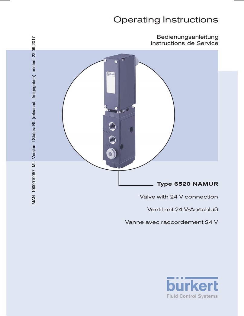
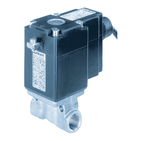
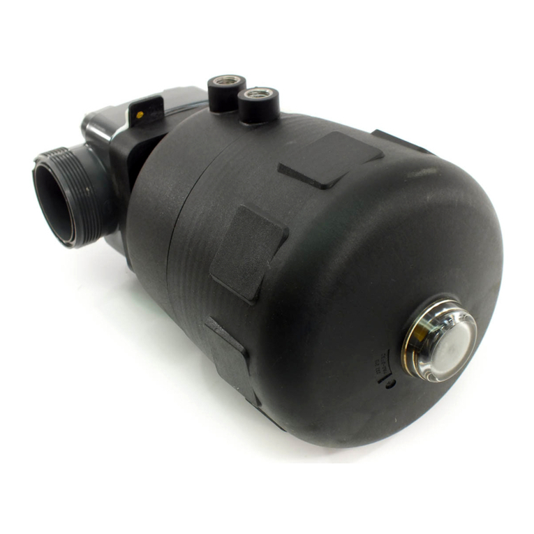
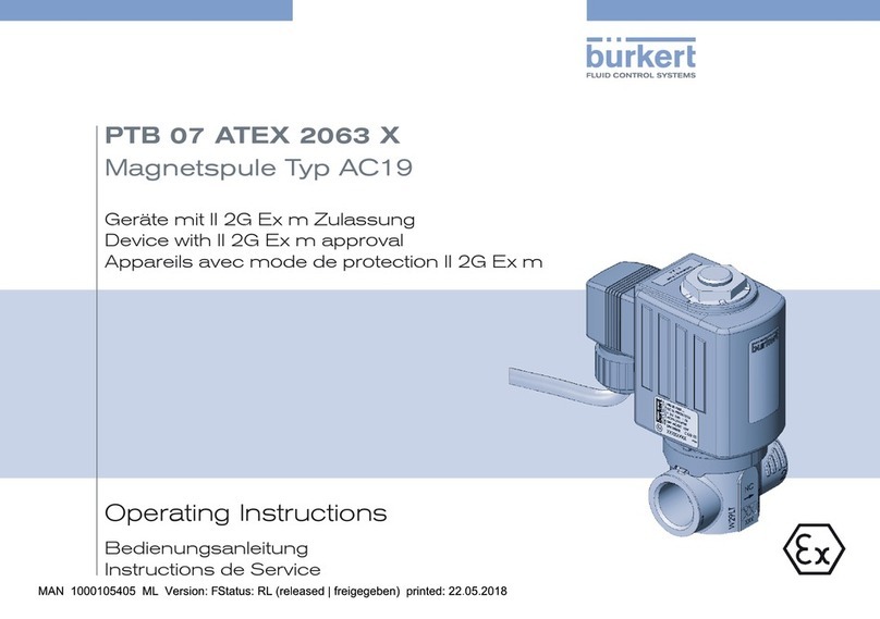
Burkert 2035 User manual

Operating Instructions
Bedienungsanleitung
Manuel d‘utilisation
Type 2035 / 3236
Robolux multiple-way diaphragm valve
Robolux Mehrwege-Membranventil
Vanne à membrane multi-voies Robolux

We reserve the right to make technical changes without notice.
Technische Änderungen vorbehalten.
Sous réserve de modifications techniques.
© Bürkert Werke GmbH & Co. KG, 200 - 2017
Operating Instructions 1706/_(8(1_00804 / Original DE

3
Contents
Type 2035 / 3236
1. OPERATING INSTRUCTIONS ...................................................................5
1.1. Symbols ..............................................................................................5
1.2. Definition of term / abbreviation ....................................................5
2. AUTHORIZED USE .........................................................................................6
2.1. Restrictions ........................................................................................6
3. BASIC SAFETY INSTRUCTIONS .............................................................6
3.1. Use in Ex area ...................................................................................7
3.2. Special conditions ...........................................................................9
4. GENERAL INFORMATION ...........................................................................9
4.1. Contact address ...............................................................................9
4.2. Warranty ............................................................................................. 9
4.3. Information on the Internet ............................................................. 9
4.4. Trademarks ......................................................................................10
5. PRODUCT DESCRIPTION ........................................................................ 10
5.1. General description .......................................................................10
5.2. Device versions ...............................................................................10
5.3. Valve self-draining ..........................................................................12
5.4. Valve symbols and flow diagrams ................................................ 13
5.5. Valve marking ..................................................................................15
5.6. Intended application area .............................................................17
6. STRUCTURE AND FUNCTION...............................................................17
6.1. Structure of Type 2035.................................................................17
6.2. Structure of Type 3236.................................................................18
7. TECHNICAL DATA ........................................................................................19
7.1. Conformity .......................................................................................19
7.2. Standards .........................................................................................19
7.3. Approvals .........................................................................................19
7.4. Type label .........................................................................................19
7.5. Operating conditions .....................................................................19
7.6. Mechanical data .............................................................................19
7.7. Fluidic data ......................................................................................21
8. ASSEMBLY .......................................................................................................23
8.1. Safety instructions .........................................................................23
8.2. Before installation ...........................................................................23
8.3. Installation ........................................................................................24
8.4. Pneumatic connection (Type 2035 only) ..................................25
8.5. Installation of the inductive proximity switch ............................26
9. OPERATION AND FUNCTION ................................................................27
9.1. Safety instructions .........................................................................27
9.2. Type 2035 - pneumatic operation ..............................................27
9.3. Type 3236 - manual operation ....................................................28
10. ELECTRICAL PRE-CONTROLLER ......................................................28
11. DISASSEMBLY ............................................................................................28
12. MAINTENANCE, CLEANING ................................................................. 29
12.1. Safety instructions .......................................................................29
12.2. Servicing intervals ........................................................................29
12.3. Servicing work ..............................................................................29
12.4. Cleaning .........................................................................................30
english

4
Type 2035 / 3236
13. REPAIRS ......................................................................................................... 31
13.1. Safety instructions .......................................................................31
13.2. Replacing the diaphragm ...........................................................31
14. SPARE PARTS ............................................................................................. 40
14.1. Order table ....................................................................................40
15. MALFUNCTIONS ........................................................................................41
16. TRANSPORT, STORAGE, PACKAGING ..........................................41
english

5
Operating instructions
Type 2035 / 3236
1. OPERATING INSTRUCTIONS
The operating instructions describe the entire life cycle of the device.
Keep these instructions in a location which is easily accessible to
every user and make these instructions available to every new owner
of the device.
WARNING!
The operating instructions contain important safety information.
Failure to observe these instructions may result in hazardous
situations.
▶The operating instructions must be read and understood.
1.1. Symbols
DANGER!
Warns of an immediate danger.
▶Failure to observe the warning will result in a fatal or serious injury.
WARNING!
Warns of a potentially dangerous situation.
▶Failure to observe the warning may result in serious injuries or
death.
CAUTION!
Warns of a possible danger.
▶Failure to observe this warning may result in a moderate or minor
injury.
NOTE!
Warns of damage to property.
▶Failure to observe the warning may result in damage to the device
or the equipment.
Indicates important additional information, tips and
recommendations.
Refers to information in these operating instructions or in
other documentation.
▶Designates an instruction to prevent risks.
→Designates a procedure which you must carry out.
1.2. Definition of term / abbreviation
In these instructions, the term 'device' always refers to the Robolux
Multiway Diaphragm Valve Type 2035 / 3236.
In these instructions, the term 'diaphragm valve' always refers to the
Robolux Multiway Diaphragm Valve Type 2035 / 3236.
In these instructions, the abbreviation “Ex” always refers
to “potentially explosive”.
english

6
Authorized use
Type 2035 / 3236
2. AUTHORIZED USE
Improper use of the Robolux Multiway Diaphragm Valve Type
2035 / 3236 may represent a hazard to persons, neighboring
equipment and the environment.
The device is designed for controlling the flow-rate of liquid media.
▶The approved data, the operating conditions and conditions of use
specified in the contract documents, operating instructions and on
the type label are to be observed during use. The designated areas
of application are specified in chapter "5. Product description".
▶Use the device only in conjunction with third-party devices and
components recommended and authorized by Bürkert.
▶Correct transportation, storage, and installation, as well as care-
ful use and maintenance are essential for reliable and faultless
operation.
▶Use the device only as intended.
2.1. Restrictions
If exporting the system/device, observe any existing restrictions.
3. BASIC SAFETY
INSTRUCTIONS
These safety instructions do not make allowance for any
• Contingencies and events which may arise during the installation,
operation, and maintenance of the devices.
• Local safety regulations – the operator is responsible for observing
these regulations, also in relation to the installation personnel.
DANGER!
Risk of injury from high pressure in the equipment/device.
▶Before working on equipment or device, switch off the pressure
and deaerate/drain lines.
Risk of electric shock.
▶Before working on equipment or device, switch off the power
supply and secure to prevent reactivation.
▶Observe applicable accident prevention and safety regulations
for electrical equipment.
WARNING!
Risk of injury when opening the actuator.
The actuator contains tensioned springs. If the actuator is opened,
injuries may be caused by the springs jumping out!
▶The actuator must not be opened.
english

7
Basic safety instructions
Type 2035 / 3236
CAUTION!
Risk of burns.
The surface of the device may become hot during long-term
operation.
▶Do not touch the device with bare hands.
Generally hazardous situations.
To prevent injuries:
▶Ensure that the system cannot be activated unintentionally.
▶Installation and repair work may be carried out by authorized
technicians only and with the appropriate tools.
▶After an interruption in the electrical or pneumatic supply, ensure
that the process is restarted in a defined or controlled manner.
▶The device must only be operated when in a perfect condition and
in consideration of the operating instructions.
▶The general rules of technology must be observed for application
planning and operation of the device.
To prevent material damage:
▶Supply only media to the media connections that are specified in
chapter "7. Technical Data" as flow media.
▶Do not place the valve under mechanical stress (e.g. by placing
objects on it or standing on it).
▶Do not make any external alterations to the valves. Do not apply
paint to body parts or screws.
3.1. Use in Ex area
Abbreviation “Ex”: see chapter "1.2. Definition of term / abbreviation"
3.1.1. Safety instructions
For operation in Ex area Zone (gas) 1 and 2,
Zone (dust) 21 and 22, the following
applies:
The valve actuator is suitable for use as a Category 2 device for
Zone 1 and 21, non-electrical production equipment.
DANGER!
Danger of explosion caused by electrostatic charge.
Depending on the conductivity of the medium, electrostatic charges
may occur on the valve membrane if plastic bodies are used.
To prevent electrostatic charges in the fluid, the following instructions
must be observed (as per IEC 60079-32-1):
▶(1) Media with a conductivity ≤ 100 pS/m may only be used if no
flow speeds > 1 m/s occur or if the possibility of the pipe system
running dry is excluded by suitable monitoring.
▶(2) Media with a conductivity > 100 pS/m and ≤ 1000 pS/m may
only be used if they are liquids without any particles, steam or pure
gases/steam, or if the instructions in (1) are observed.
▶(3) Media with a conductivity > 1000 pS/m are not subject to any
restrictions.
english

8
Basic safety instructions
Type 2035 / 3236
Further instructions:
▶The user must ensure that the appliance is used in Zone 1/21 or
2/22 only.
▶The attachment of feedback indicators may restrict use in an
explosive atmosphere. Follow operating instructions for feedback
indicator.
▶Check that any cleaning agents are approved for use in explosive
atmospheres.
3.1.2. Media temperature
DANGER!
▶If explosive media are used this can cause additional explosion risks.
▶If media temperatures are used between 130 °C and 150 °C, the
temperature class T3 / 200 °C applies (dust).
Media temperature The media temperature must not be higher
than the target temperature class.
3.1.3. Marking and warning notices in Ex
area
Type 2035
PTB 13 ATEX D103 X
II 2G c IIC T6
II 2D c T85°C
Warning:
Not valid when Non-Ex devices added.
Do not open actuator. Spring loaded cover.
Clean the surface with appropriate
cleaning agent only!
Fig. 1: Type 2035 marking and warning notices in Ex area
Type 3236
PTB 13 ATEX D103 X
II 2G c IIC T6
II 2D c T85°C
Caution:
Clean the surface with appropriate
cleaning agent only!
Fig. 2: Type 3236 marking and warning notices in Ex area
english

9
General information
Type 2035 / 3236
The Ex marking is not valid if Non-Ex devices are added.
3.2. Special conditions
→To ensure potential equalization, ground the valve body to the
pipe system using an electrically conductive connection.
DANGER!
Danger of explosion caused by electrostatic charge.
In the event of a sudden discharge from electrostatically charged
devices or individuals there is a risk of an explosion in the Ex area.
▶Implement suitable measures to ensure that there are no electro-
statically charges in the Ex area (see also "3.1. Use in Ex area").
▶Clean the device surface by gently wiping it with a damp or anti-
static cloth only.
▶Earth the actuator and valve body.
▶If a plastic body is used, earth the actuator separately.
Ambient temperature range: -10 °C ≤ Tamb ≤ 60 °C
4. GENERAL INFORMATION
4.1. Contact address
Germany
Bürkert Fluid Control Systems
Sales Center
Christian-Bürkert-Str. 13-17
D-74653 Ingelfingen
Tel. + 49 (0) 7940 - 10 91 111
Fax + 49 (0) 7940 - 10 91 448
Email: [email protected]
International
Contact addresses can be found on the final pages of the printed
operating instructions.
And also on the Internet at: www.burkert.com
4.2. Warranty
The warranty is only valid if the diaphragm valve is used as intended in
accordance with the specified application conditions.
4.3. Information on the Internet
The operating instructions and data sheets for Types 2035 / 3236 can
be found on the Internet at:
www.burkert.com
english

10
Product description
Type 2035 / 3236
4.4. Trademarks
Brands and trademarks listed below are trademarks of the respective
companies / associations / organizations:
PFR 91 Solvey Solexis Inc.
PFA DuPont Performance Elastomers
Inbus Textron Verbindungstechnik GmbH & Co. oHG
5. PRODUCT DESCRIPTION
5.1. General description
The manually or pneumatically operated Robolux Multiway Dia-
phragm Valves1) have been designed as a system for the control
of ultra-pure, sterile, aggressive or abrasive media. They allow for
optimal collection, draining or distribution of critical process media.
Observe instructions on operation in an explosion-risk (Ex)
area. See chapter "3.1. Use in Ex area".
1) In the following text the Robolux Multiway Diaphragm Valve is
referred to as 'diaphragm valve' for brevity's sake.
5.2. Device versions
The diaphragm valve is available in two variants with either a pneu-
matically or manually operated valve.
The diaphragm valve can be adapted to very different usage condi-
tions on account of its modular design.
Depending on the connection size of the diaphragm valves three
construction sizes are available (RV5O, RV7O, RV110).
The valve body is made from a stainless steel block. For certain
usage conditions valve bodies made of plastic (PVDF or PP) are
available.
english

11
Product description
Type 2035 / 3236
High-quality diaphragms ensure complete separation of the critical
medium from the actuator.
Depending on the function the valve can have one, two or three
actuators.
The diaphragm valves can be used for a large variety of control func-
tions. Accordingly, there is a very wide range of configuration varia-
tions. For instance, according to function:
• the valves in the actuator can vary,
• the actuators can have one or two control pistons that can be
operated independently of each other,
• pneumatic actuators can be equipped with inductive proximity
switches for querying the various switching states.
5.2.1. Pneumatically operated diaphragm
valve Type 2035
The valve has one or two pneumatic actuators that are controlled via
compressed air.
Pneumati-
cally operated
actuator
Diaphragm
Valve body
Diaphragm
Fig. 3: Pneumatically operated diaphragm valve, structure and
description
english

12
Product description
Type 2035 / 3236
5.2.2. Manually operated diaphragm valve
Type 3236
The valve is operated manually.
Manually
operated
actuator
Diaphragm
Valve body
Fig. 4: Manually operated diaphragm valve, structure and
description
5.3. Valve self-draining
The way in which self-draining takes place varies according to the
valve type. It is very important to know the flow paths for each indi-
vidual valve before the port / connection (marked with A, B, C or D)
for draining is selected.
Contact your Bürkert sales office or our Sales Center, email:
[email protected] if you have any queries.
The following examples illustrate draining for the valve types 3C2S /
4C2S and 4C4S DFP.
3C2S / 4C2S
drainage connection B (D)
3C2S / 4C2S
drainage connection C (A)
Installation positions for self-drainage:
AC
B
D
AC
B
AC
B
B
C
A
Fig. 5: Self-draining - 3C2S / 4C2S
english

13
Product description
Type 2035 / 3236
A
C
B
B
C
A
4C4S DFP
drainage connection
A (C)
4C4S DFP
drainage connection
B (D)
Installation positions for self-drainage:
D
D
AC
B
D
Fig. 6: Self-draining - 4C4S DFP
5.4. Valve symbols and flow diagrams
3 connections, 2 seats
3C2S
Seat
U1
Seat
U2
AC
B
AC
B
Fig. 7: Valve symbols and flow diagrams - 3C2S
4 connections, 2 seats
4C2S
Seat
U1
Seat
U2
AC
B
D
AC
B
D
Fig. 8: Valve symbols and flow diagrams - 4C2S
english

14
Product description
Type 2035 / 3236
3 connections, 3 seats
3C3S
upper side lower side
Seat
U1
Seat
U2
CA
DSeat
L1 D
AC
CA
D
Fig. 9: Valve symbols and flow diagrams - 3C3S
4 connections, 3 seats
4C3S
upper side lower side
Seat
U1
Seat
U2
A C
B
D
Seat
L1 B
C A
D
AC
B
D
Fig. 10: Valve symbols and flow diagrams - 4C3S
4 connections, 3 seats
4C3S BD filter valve
upper side lower side
Seat
U1
Seat
U2
B
A
C
D
Seat
L2
D
C
A
BBD
C
A
Fig. 11: Valve symbols and flow diagrams - 4C3S BD
4 connections, 4 seats
4C4S
upper side lower side
Seat
U1
Seat
U2
AC
B
D
Seat
L2
Seat
L1 B
CA
D
AC
B
D
Fig. 12: Valve symbols and flow diagrams - 4C4S
english

15
Product description
Type 2035 / 3236
4 connections, 4 seats
4C4S DFP through-flow double valve
upper side lower side
Seat
U1
Seat
U2
A
D
B
C
Seat
L2
Seat
L1
C
B
D
AAC
B
D
Fig. 13: Valve symbols and flow diagrams - 4C4S DFP
4 connections, 5 seats
4C5S chromatography valve
upper side lower side
Seat
U1
Seat
U2
B1
AC
Seat
L2
Seat
L1
CA
B1B2
AC
B2
B1
Fig. 14: Valve symbols and flow diagrams - 4C5S
5.5. Valve marking
Type label
Marking and warning
notices in Ex area
Actuator orientation
marking
Port connection
markings
Valve body labeling
Orifice and connection dimensions
Material, charge, manufacturing
order and serial No.
Fig. 15: Valve marking
english

16
Product description
Type 2035 / 3236
5.5.1. Type label
2035 RV50 4C 4S-DFP
EPDM-cus D11 -D11
Weld end 19.05x1.65
Pilot 4.2-10 bar
Pmed 10bar
12345678
Made in Germany
W14UN
Identification number
Size
Connection type -
connection dimensions
Type Diaphragm material -
actuator 1 - actuator 2
Date of manufacture
Max. medium pressure
Pilot pressure
Design
Fig. 16: Type label Type 2035
Robolux
3236 RV50 4C 4S-DFP
EPDM-cus D44 -D44
Weld end 19.05x1.65
Pmed 10bar
12345678
Made in Germany
W14UN
Identification number
Connection type -
connection dimensions
Diaphragm material -
actuator 1 - actuator 2
Date of manufacture
Max. medium pressure
Type - Size - Design
Fig. 17: Type label Type 3236
5.5.2. Marking and warning notices in Ex
area
See chapter "3.1.3. Marking and warning notices in Ex area".
5.5.3. Port connection markings
All port connections are provided with letters corresponding to the
flow diagrams (see chapter "5.4. Valve symbols and flow diagrams").
5.5.4. Actuator orientation marking
The actuator has a marking close to connection A as an aid to
ensure correct assembly.
Fig. 18: Actuator orientation marking
english

17
Structure and function
Type 2035 / 3236
5.6. Intended application area
The diaphragm valve has been designed for use with soiled and
aggressive media which do not corrode the body and the seal
materials.
Observe the maximum pressure range according to the
type label.
• Ultra-pure, sterile, aggressive or abrasive media.
• Highly viscous media.
Observe instructions on operation in an explosion-risk (Ex)
area. See chapter "3.1. Use in Ex area".
5.6.1. Application areas
e.g. plant construction
luxury food and food processing industry
bottling plant
chemical engineering
pharmaceutics
6. STRUCTURE AND FUNCTION
6.1. Structure of Type 2035
The diaphragm valve consists of a pneumatically operated piston
actuator, diaphragm and multi-port valve body.
Actuator cover
Actuator body
Body screws / nuts
Diaphragm
Valve body
Silencer
Pilot air port
Cover position
proximity switch
Cover screw
pressure piece
Fig. 19: Piston-controlled diaphragm valve, structure and
description
english

18
Structure and function
Type 2035 / 3236
6.1.1. Actuator
The actuator has two actuator chambers that can be controlled
independently of each other and act on one body seat each (double
action). Where only one actuator is in operation only one actuator
chamber is equipped with the internal functional parts.
Spring force (CFA, NC) or pneumatic pilot pressure (CFB, NO)
generates the closing force of the actuator.
The force is transmitted onto the corresponding pressure piece and
the diaphragm in each case via a spindle connected to the actuator
piston.
6.1.2. Control functions (CF)
Control function A, NC (CFA)
Closed by spring force in rest
position
1(P)
2(A)
Control function B, NO (CFB)
Opened by spring force in rest
position
1(P)
2(B)
6.2. Structure of Type 3236
The diaphragm valve consists of a manually operated actuator,
diaphragm and multi-port valve body.
Hand wheel
Actuator body
Body screws
Diaphragm
Valve body
Fig. 20: Manually operated diaphragm valve, structure and
description
6.2.1. Actuator
The actuator has two hand wheels that can be controlled indepen-
dently of each other and act on one body seat each (double action).
Where only one actuator is in operation only one actuator side con-
tains functional parts.
The force is transmitted onto the corresponding pressure piece and
the diaphragm in each case via a spindle connected to the hand
wheel.
english

19
Technical Data
Type 2035 / 3236
7. TECHNICAL DATA
7.1. Conformity
The diaphragm valves of Type 2035 and 3236 comply with EC Direc-
tives in accordance with the EC Declaration of Conformity.
7.2. Standards
The applied standards on the basis of which compliance with the EC
Directives is confirmed are listed in the EC type examination certificate
and/or the EC Declaration of Conformity.
7.3. Approvals
The product is approved for use in zone 1 and 21 in accordance
with ATEX directive 94/9/EC category 2 GD.
Observe instructions on operation in an explosion-risk (Ex)
area. See chapter "3.1. Use in Ex area".
Valve body stainless steel: EN ISO 10204 3.1
polypropylene: USP VI (material PR)
diaphragm FDA CFR 177.2600 for EPDM, FKM and silicone
FDA CFR 177.1550 for PFA
USP VI for EPDM, PFA/EPDM, silicone and PFR 91
7.4. Type label
See chapter "5.5. Valve marking".
7.5. Operating conditions
Observe permitted pressure ranges given on the type label
of the device.
Ambient temperature -10 – +60 °C
higher temperatures on request
Operating temperature max. +85 °C
Relative humidity max. 80 % (non-condensing)
7.6. Mechanical data
Dimensions see data sheet
Materials
Body material stainless steel: 1.4435/316L
(other materials on request)
PP (ultra-pure polypropylene)
PP (polypropylene USP VI)
PVDF (sterile polyvinyl-difluoride)
Diaphragm EPDM, silicone, PFA/EPDM, FKM, PFR 91
Actuator epoxy powder coated aluminum
PP body (only type 2035 RV50)
english

20
Technical Data
Type 2035 / 3236
Connections
Port connections welded spigots DIN EN ISO 1127
(ISO 4200), DIN 11850 Series 2,
ASME BPE
SMS 3008, BS4825 (other welded con-
nections, clamps and sterile screw fittings
on request)
Pilot air port G1/8
Surface quality interior Ra 0.5 µm passivated
exterior Ra 3.2 µm glass bead blasted
optional electro-polished
(other surface finishes on request)
Installation position any position; preferably connection B
downwards; for self-drainage see chapter
"5.3. Valve self-draining"
Service life
The service life of the device depends heavily on the conditions of use.
Especially the service life of the diaphragm depends very heavily on
the conditions of use, such as the medium, temperatures, switching
frequency, pressure etc.
7.6.1. Diaphragm
The diaphragm seals the valve. It must be selected with care. The
choice of material should be made bearing in mind the process
medium, the temperature and the mechanical boundary conditions
(e.g. operating pressure, switching frequency etc.).
The standard materials are contained in the following table.
For conformity with FDA CFR 21 Para. 177.2600 or Para. 177.1550
and USP VI certification, see "Tab. 1: Diaphragm materials".
Diaphragm
material
Description of
material
Use FDA USP VI
EPDM peroxide-vulcanized
ethylene-propylene
rubber
oxidizing
chemicals,
steam and hot
water
x x
PFA /
EPDM
PFA
laminated EPDM
most chem-
icals and acids
x x
FKM fluorinated rubber acids and
mineral oils
x
silicone platinum-stabilized
silicone rubber
aliphatic oils x x
PFR 91 PFR 91
fluorinated rubber
aliphatic oils x
Tab. 1: Diaphragm materials
english
This manual suits for next models
1
Table of contents
Languages:
Other Burkert Control Unit manuals

Burkert
Burkert 3233 User manual

Burkert
Burkert 3270 User manual

Burkert
Burkert 6026 User manual

Burkert
Burkert 0340 User manual

Burkert
Burkert 6213 User manual

Burkert
Burkert 6430 User manual

Burkert
Burkert 6027 User manual

Burkert
Burkert 2100 series User manual

Burkert
Burkert 0301 User manual

Burkert
Burkert 2503 User manual

Burkert
Burkert PTB 00 ATEX 2129 X User manual

Burkert
Burkert 0420 User manual

Burkert
Burkert 3281 User manual

Burkert
Burkert 6228 User manual

Burkert
Burkert 0211 User manual

Burkert
Burkert 0283 User manual

Burkert
Burkert 5281 EV User manual

Burkert
Burkert 3232 User manual

Burkert
Burkert 6511 User manual

Burkert
Burkert 2030 User manual