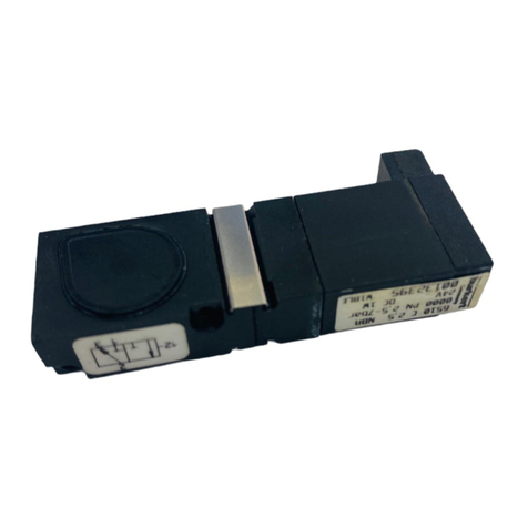
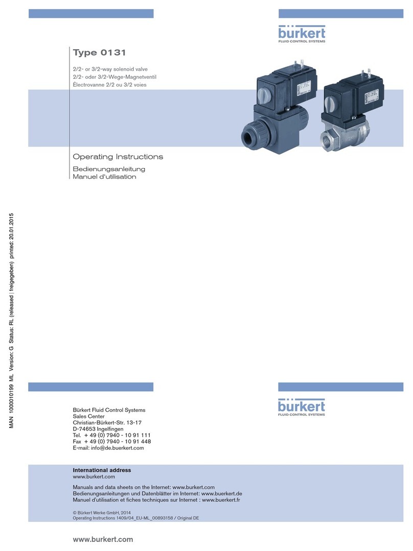
Burkert 0127 User manual

Bedienungsanleitung
Manuel d‘utilisation
Operating Instructions
Type 0127
Rocker valve
2/2 or 3/2-way solenoid valve
2/2 oder 3/2-Wege Magnetventil
Vanne magnétique 2/2 ou 3/2

2
1 OPERATING INSTRUCTIONS
The operating instructions contain important information.
▶Read the instructions carefully and follow the safety instructions
in particular, and also observe the operating conditions.
▶Instructions must be available to each user.
▶The liability and warranty for Type 0127 are void if the operating
instructions are not followed.
1.1 Symbols
→designates a procedure which you must carry out.
▶Designates an instruction to prevent risks.
Warning of injuries:
Danger!
Imminent danger. Serious or fatal injuries.
Warning!
Potential danger. Serious or fatal injuries.
Caution!
Danger. Minor or moderately severe injuries.
Warns of damage to property:
note!
Contents
1 Operating Instructions ................................................................. 2
2 Intended use ............................................................................... 3
3 Basic safety instructions .............................................................. 3
4 Modularity ................................................................................... 4
5 Technical Data ............................................................................. 5
6 Installation ..................................................................................... 7
7 Maintenance / Malfunctions....................................................... 11
8 Replacement parts .................................................................... 11
9 Transport, Storage, Disposal...................................................... 11
english

3
2 INTENDED USE
Valve Type 127 has been designed as a rocker solenoid valve
with isolating diaphragm.
It is suitable for laboratory, medical and analysis technology
▶Use according to the authorized data, operating conditions,
and conditions of use specied in the contract documents and
operating instructions.
▶The valve must not be used outdoors.
▶Use the device only in conjunction with third-party devices and
components recommended and authorized by Bürkert.
▶Use device only when in perfect condition and always ensure
proper storage, transportation, installation and operation.
▶Use the device only as intended.
2.1 Denition of term
The term “device” used in these instructions always stands for the
ipper solenoid valve type 0127.
3 BASIC SAFETY INSTRUCTIONS
These safety instructions do not make allowance for any contin-
gencies and events which may arise during installation, operation
and maintenance.
Danger – high pressure.
▶Before loosening the lines and valves, turn o the pressure and
vent the lines.
Risk of injury due to electric shock.
▶Before working on the system or device, switch o the power
supply and secure to prevent reactivation.
▶Observe applicable accident prevention and safety regulations
for electrical equipment.
Risk of burns/risk of re if used continuously through hot device
surface.
▶Keep the device away from highly ammable substances and
media and do not touch with bare hands.
Leaking medium when the diaphragm is worn.
▶Regularly check for leaking medium.
▶If the media is hazardous, protect the environment from danger.
english

4
General hazardous situations.
To prevent injuries:
▶Do not make any internal or external changes on the device and
do not subject it to mechanical stress.
▶Secure to prevent unintentional actuation.
▶Only trained technicians may perform installation and mainte-
nance work.
▶The valves must be installed in accordance with the regulations
applicable in the country.
▶After an interruption in the power supply, ensure that the pro-
cess is restarted in a controlled manner.
▶Observe the general rules of technology.
note!
Electrostatic sensitive components / modules.
The power reduction electronics, which is available as an
accessory, contains electronic components which react sensi-
tively to electrostatic discharge (ESD). Contact with electrostati-
cally charged persons or objects is hazardous to these compo-
nents. In the worst case scenario, they will be destroyed immedi-
ately or will fail after start-up.
•Observe the requirements in accordance with EN 61340-5-1 and
5-2 to minimize or avoid the possibility of damage caused by a
sudden electrostatic discharge.
•Do not touch live electronic components.
4 MODULARITY
The valve is modular in design and can be supplied with dierent
line connections according to the application case. It can be used
individually and in blocks.
english

5
5 TECHNICAL DATA
5.1 Operating Conditions
Warning!
Risk of injury.
Malfunction if used outside.
▶Do not use Type 0127 outside and avoid heat sources which
may cause the permitted temperature range to be exceeded.
Ambient temperature 0 ... +55 °C
Medium temperature
Nominal width Seal material Temperature range
DN 0,8 FFKM +5...+50 °C
DN 0,8 FKM 0...+50 °C
DN 0,8 EPDM -5...+50 °C
DN 1,2 und 1,6 FFKM +10...+50 °C
DN 1,2 und 1,6 FKM +5...+50 °C
DN 1,2 und 1,6 EPDM -5...+50 °C
Media neutral and aggressive liquids and
gases which do not corrode the
housings and seal materials (see resistance table
at www.burkert.com → Type)
Protection class IP54 with wires and individual device socket
IP20 with multi-device socket
5.2 Conformity
The solenoid valve Type 0127 conforms to the EU directives
according to the EU Declaration of Conformity (if applicable).
5.3 Standards
The applied standards, which are used to demonstrate compliance with
the EU Directives, are listed in the EU type test certicate and/or the EU
Declaration of Conformity (if applicable).
5.4 Mechanical Data
Dimensions see data sheet
Housing material PVDF, ETFE, PEEK,PPS
Sealing material FFKM, FKM, EPDM
english

6
5.5 Pneumatic Data
Operating principles
A
A
P/NC
2/2-way valve, direct action, closed with no
current
B
B
P/NO
2/2-way valve, direct action, opened with
no current
T
A in/out
P/NC R/NO
3/2-way valve, direct-acting,
all-purpose
Pressure range see type label
Line connections Threaded connection G1/8,
NPT1/8 or UNF1/4-28
Flanged connection
Hose connection
Note the information specied on the rating plate for voltage,
type of current, and pressure.
5.5.1 Rating plate (example)
Ident. no.
Voltage/frequency output
Nominal connection pressure
Type
Operating principle
Nominal width
Seal material
Housing materia
if applicable
Made in Germany
0127 T 1,6 FFKM PD
PN0-2 bar / 29 PSI
24V AC/DC 3W
S/N 1940
00073606 W13ME
english

7
5.6 Electrical Data
Operating voltage 12 V DC
24 V DC
24 V UC
Voltage tolerance ± 10 %
Nominal power
12-24 V 3.0 W
Nominal operating mode Long-term operation,
duty cycle 100 %
for block assembly if temperatures of media or
surrounding area above +40 °C:
intermittent duty 40% (10 min)
Note the information specied on the rating plate for voltage,
type of current, and pressure.
6 INSTALLATION
6.1 Safety Instructions
Warning!
Risk of injury when installing the valve.
▶This work may be carried out by authorised technicians only and
with the appropriate tools.
▶After an interruption in the power supply or pneumatic supply,
ensure that the process is restarted in a dened or controlled
manner.
6.2 Fluid Installation
Danger!
Danger – high pressure.
Danger of severe injuries from reaching into the system.
▶Before loosening the lines and valves, turn o the pressure and
vent the lines.
Installation position: any position, preferably with the drive facing
up.
english

8
Installation
→Before installation, clean any possible dirt o the pipelines and
ange connections.
→If required, install a dirt trap to prevent malfunctions.
Mesh size: 5 µm
Observe the direction of ow of the valve.
Operating principle*
A
T
B
* see also the description of the operating principles in the chapter entitled
“Pneumatic Data”
Identication of the valve connections on the housing:
NO Normally Open Connection normally openfor WWB
NC Normally Closed Connection normally closed, for WWA
IN/OUT for pressure connection (distributor) or
work connection (mixer), for WWT
The valve housing must not be twisted by the fastening screws
or by screwing in the connecting nipples too far.
The housings with threaded or hose connection have xing eyelets
for the screw connection from above with M3 and from below with
self-tapping screws BZ 3.9 x ... DIN 7971.
Housing with threaded connection:
→Use PTFE tape as sealing material
→Screw in the connecting thread by hand only
Housing with hose connection:
→Use exible silicone or FKM hose with 1.6-2 mm inner diameter
Valve with anged connection:
→Remove the locking plate (coloured orange).
english

9
Do not remove the anged plate.
Warning!
Danger – escaping medium.
Leaking connections if seals not seated properly, if connection plate
uneven or if surface quality of the connection plate inadequate.
▶Make certain the seals included with delivery are properly seated
in the valve.
▶Ensure that the connection plate is even.
▶Ensure that the surface quality of the connection plate is
adequate.
→Insert the seal into the valve.
Caution!
If the tightening torque is too great, the device may be
damaged.
▶Observe the max. tightening torque of the screws.
Screw in screws to 0.3 ± 0.05 Nm
(does not apply to self-tapping
screws)
Caution:
Do not remove
anged plate !
→Attach valve to the connection plate.
Dimensional drawing for connection plate:
NO
IN/OUT
NC
M2.5 min 8.5 deep
max. ø2
18
21.5
10.5
Arrangement of the bores:
3-way 2-way central exit 2-way external exit
english

10
6.3 Electrical Installation
Danger!
Risk of electric shock when reaching into the equipment.
▶Before starting work, always switch o the power supply and
safeguard to prevent re-activation.
▶Observe applicable accident prevention and safety regulations
for electrical equipment.
Note the voltage and current type as specied on the rating
plate.
Voltage tolerance±10%
Connection to device socket:
Danger!
Risk of electric shock if protective conductor not connected.
▶Always connect protective conductor.
Earthing connection (if tted): Middle plug tab
Ensure that the at seal is seated correctly for the electrical
connection to the device socket.
Device socket
Type 1054
Flat seal
Valve
max. tightening torque:
0.4 Nm
Caution!
If the tightening torque is too great, the device may be
damaged.
▶Observe the max. tightening torque of the screw.
→Screw device socket to valve to a max. tightening torque of 0.4 Nm.
Alternative electrical connection:
Two individual wires
english

11
7 MAINTENANCE / MALFUNCTIONS
→Regularly check for leaking medium.
7.1 Malfunctions
If malfunctions occur, check
→the line connections
→the operating pressure
→the power supply and valve control.
If the valve still does not switch, please contact your Bürkert Service.
8 REPLACEMENT PARTS
Caution!
Using the wrong accessories or replacement parts may be
dangerous.
Incorrect accessories and spare parts may cause injuries and
damage the device and the surrounding area.
▶Use only original accessories and original spare parts supplied
by Bürkert.
Accessories and replacement parts available on request.
9 TRANSPORT, STORAGE, DISPOSAL
note!
Transport damages.
Inadequately protected equipment may be damaged during
transport.
▶During transportation protect the device against wet and dirt in
shock-resistant packaging.
▶Avoid exceeding or dropping below the permitted storage
temperature.
Incorrect storage may damage the device.
▶Store the device in a dry and dust-free location.
▶Storage temperature: -40...65 °C.
Damage to the environment caused by device components
contaminated with media.
▶Observe applicable regulations on disposal and the
environment.
▶Observe national waste disposal regulations.
english

www.burkert.com
International address
www.burkert.com
Manuals and data sheets on the Internet: www.burkert.com
Bedienungsanleitungen und Datenblätter im Internet: www.buerkert.de
Manuels d'utilisation et fiches techniques sur Internet : www.burkert.fr
© Bürkert Werke GmbH & Co. KG, 2015 - 2019
Operating Instructions 1903/07_EU-ML_00893191 / Original DE
Bürkert Fluid Control Systems
Sales Center
Christian-Bürkert-Str. 13-17
D-74653 Ingelfingen
Tel. + 49 (0) 7940 - 10 91 111
Fax + 49 (0) 7940 - 10 91 448
E-mail: [email protected]
Other manuals for 0127
1
Table of contents
Other Burkert Control Unit manuals

Burkert
Burkert 3280 User manual

Burkert
Burkert 2301 Series User manual

Burkert
Burkert 8691 User manual

Burkert
Burkert Robolux 2036 User manual

Burkert
Burkert 2106 User manual

Burkert
Burkert 3320 User manual

Burkert
Burkert 3280 User manual

Burkert
Burkert 2101 User manual

Burkert
Burkert WhisperValve 6724 User manual

Burkert
Burkert 2060 User manual

Burkert
Burkert Type 2000 User manual

Burkert
Burkert 6524 User manual

Burkert
Burkert 2030 User manual

Burkert
Burkert 2610 User manual

Burkert
Burkert 2080 User manual

Burkert
Burkert 2301 Series User manual

Burkert
Burkert 2030 User manual

Burkert
Burkert 2300 Series User manual

Burkert
Burkert 0301 User manual

Burkert
Burkert 5406 User manual