SKF UFD20 Series User manual

Version 06
951-170-218-EN
EN
Assembly instructions
acc. to Machinery Directive 2006/42/EC
DigitalSuper
of series UFD10 and UFD20
Minimal quantity lubrication system for internal lubrication

EC Declaration of Incorporation acc. to Machinery Directive 2006/42/EC, Appendix II Part 1 B
The manufacturer, SKF Lubrication Systems Germany GmbH, Berlin Plant, Motzener Straße 35 -37, DE - 12277 Berlin, hereby declares conformity of the
partly completed machinery
Designation: Minimal Quantity Lubrication Systems for Internal Lubrication
Type: DigitalSuper
Item number: UFD10-1-XXXXXX; UFD20-1-10XXXX
Year of manufacture: See rating plate
with the essential protection requirements of Machinery Directive 2006/42/EC at the time of placing on the market.
1.1.2 · 1.1.3 · 1.3.2 · 1.3.4 · 1.5.1 · 1.5.6· 1.5.8 · 1.5.9 · 1.6.1 · 1.7.1 · 1.7.3 · 1.7.4
The technical documentation described in Annex VII, Part B of this Directive has been prepared. We undertake to transmit, in response to a reasoned request
by the national authorities, the special documents for this partly completed machine. The Head of Technical Standards is the authorized representative for
the technical documentation. See the manufacturer information for the address.
Furthermore, the following Directives and (harmonized) standards were applied in the applicable areas:
2011/65/EU RoHS II
2014/30/EU Electromagnetic Compatibility | Industry
Standard Edition Standard Edition Standard Edition Standard Edition
DIN EN ISO 12100 2013 DIN EN 60947-5-1 2010 DIN EN 61000-6-2 2006 DIN EN 61000-6-4 2011
DIN EN 809 2012 DIN EN 61131-2 2008 Correction 2011 DIN EN 60947-5-1 2010
DIN EN 60204-1 2007 Correction 2009 DIN EN 61000-6-3 2011
Correction 2010 DIN EN 60034-1 2015 Correction 2012
DIN EN 50581 2013 DIN EN 61000-6-1 2007
The partially completed machinery must not be put into service until the machinery into which it is to be incorporated has been declared in conformity with
the provisions of Machinery Directive 2006/42/EC and all other applicable Directives.
Berlin, September 30, 2016
Jürgen Kreutzkämper
Manager R&D Germany
SKF Lubrication Business Unit
Dr.-Ing. Holger Schmidt
Manager Development Center Berlin
Lubrication Business Unit
- 2 -
951-170-218-EN
Version 06
EN
EC Declaration of Incorporation

- 3 -
951-170-218-EN
Version 06
EN
Masthead
Training
SKF conducts detailed training in order to
enable the maximum safety and efficiency.
SKF recommends taking advantage of this
training. For information, contact the rel-
evant SKF service address.
Copyright
© Copyright SKF
All rights reserved.
Warranty
The instructions do not contain any infor-
mation on the warranty. This can be found in
our General Terms and Conditions.
Disclaimer of liability
The manufacturer shall not be held liable for
damage resulting from:
○Improper usage, assembly, operation,
configuration, maintenance, repair, or
accidents
○Improper reaction to malfunctions
○Unauthorized modifications to the
product
○Intentional or gross negligence
○Use of non-original SKF spare parts
The maximum liability for loss or damage
resulting from the use of our products is
limited to the purchase price. Liability for
indirect damage of any kind is excluded.
Masthead
Manufacturer
SKF Lubrication Systems Germany GmbH
Addresses of manufacturer plants
Headquarters
Walldorf Plant
Heinrich-Hertz-Str. 2-8
69190 Walldorf
Germany
Tel: +49 (0) 6227 33-0
Fax: +49 (0) 6227 33-259
Berlin Plant
Motzener Straße 35/37
12277 Berlin
Germany
Tel. +49 (0)30 72002-0
Fax +49 (0)30 72002-111
Hockenheim Plant
2. Industriestraße 4
68766 Hockenheim
Germany
Tel. +49 (0)62 05 27-0
Fax +49 (0)62 05 27-101
E-mail: Lubrication-german[email protected]om
www.skf.com/lubrication

- 4 -
951-170-218-EN
Version 06
EN Table of contents
Table of contents
EC Declaration of Incorporation ..........................................................................2
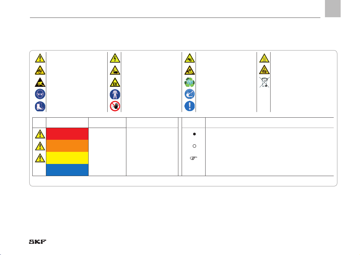
Explanation of symbols and signs ........................................................................7
1. Safety instructions ................................................................ 9
1.1 General safety instructions ....................................................................9
1.2 General behavior when handling the product .....................................9
1.3 Intended use ..........................................................................................10
1.4 Foreseeable misuse ..............................................................................10
1.5 Modifications to the product ................................................................11
1.6 Inspections prior to delivery ................................................................11
1.7 Referenced documents ........................................................................11
1.8 Notes on the rating plate .....................................................................11
1.9 Note on CE marking .............................................................................12
1.10 Persons authorized to use the product ..............................................12
1.10.1 Operator ...........................................................................................12
1.10.2 Qualified mechanic .........................................................................12
1.10.3 Qualified electrician ........................................................................12
1.11 Instruction of outside fitters ................................................................12
1.12 Provision of personal protective gear .................................................13
1.13 Operation ...............................................................................................13
1.14 Emergency shutdown ..........................................................................13
1.15 Transport, assembly, maintenance, malfunction,
repair, shutdown, disposal ...................................................................13
1.16 Initial commissioning, daily startup ....................................................15
1.17 Cleaning .................................................................................................15
1.18 Residual risks ........................................................................................16
2. Lubricants .......................................................................... 18
2.1 General information .............................................................................18
2.2 Selection of lubricants ..........................................................................18
2.3 Material compatibility ...........................................................................19
2.4 Aging of lubricants ................................................................................19
3. Overview, functional description .......................................... 20
3.1 Principle of minimal quantity lubrication ...........................................20
3.2 Principle of aerosol action ...................................................................20
3.3 General function and design ...............................................................20
3.4 Main components of a UFD minimal quantity lubrication system..22
3.4.1 Aerosol generator ..........................................................................22
3.4.2 Control unit ......................................................................................23
3.4.3 Communication interface ..............................................................24
3.4.4 Flow sensor .....................................................................................24
3.4.5 Fill level indicator and monitoring ................................................24
3.4.6 Main air valve (compressed air connection) ................................24
3.4.7 Pressure gauge ...............................................................................25
3.4.8 Fine filter for compressed air ........................................................25
3.4.9 Lubricant drain valve ......................................................................25
3.4.10 Safety valve .....................................................................................25
3.5 Design-specific components ...............................................................26
3.5.1 PROFIBUS communication interface ...........................................26
3.5.2 PROFINET communication interface ...........................................29
3.5.3 Automatic filling pump ...................................................................32
3.5.4 Automatically controlled bypass valve – bypass control ............32
3.6 System designs and type codes .........................................................35
3.6.1 Minimal quantity lubrication systems with
one aerosol generator ....................................................................38
3.6.2 Minimal quantity lubrication systems with
two aerosol generators ..................................................................54

- 5 -
951-170-218-EN
Version 06
EN
Table of contents
4. Technical data ..................................................................... 58
4.1 General technical data ..........................................................................58
5. Delivery, returns, storage .................................................... 60
5.1 Delivery ..................................................................................................60
5.2 Return shipment ...................................................................................60
5.3 Storage ...................................................................................................60
6. Assembly ............................................................................ 61
6.1 General information .............................................................................61
6.2 Assembly location .................................................................................61
6.3 Mechanical connection .........................................................................62
6.3.1 Minimum mounting dimensions ..................................................62
6.4 Tightening torques ...............................................................................62
6.5 Assembly holes .....................................................................................62
6.5.1 Attaching MQL systems .................................................................63
6.6 Minimum installation and mounting dimensions ............................64
6.6.1 MQL UFD10-1-100000 and UFD10-1-101000 ......................64
6.6.2 MQL UFD10-1-200000 and UFD10-1-201000 ......................65
6.6.3 MQL UFD10-1-110000 and UFD10-1-111000 ......................66
6.6.4 MQL UFD10-1-210000 and UFD10-1-211000 ......................67
6.6.5 MQL UFD20-1-100000 and UFD20-1-101000 ......................68
6.7 Connection of aerosol lines .................................................................69
6.7.1 General notes on the connection of aerosol lines .......................69
6.7.2 Connection of aerosol lines to an MQL system
with bypass control .........................................................................72
6.7.3 Connection of aerosol lines to an optional
SKF aerosol monitor (AM1000) ....................................................74
6.8 Electrical connection ............................................................................75
6.8.1 Connector pin assignment on standard designs.........................76
Customer connectivity for
6.8.2 UFD10-1-1XX000 with PROFIBUS ..................................................78
6.8.3 UFD10-1-2XX000 with PROFINET ...................................................79
6.8.4 UFD10-1-20000 / UFD10-1-201000.............................................80
6.8.5 UFD10-1-110000 / UFD10-1-111000 ..........................................81
6.8.6 UFD10-1-210000 / UFD10-1-211000 ..........................................82
6.8.7 Customer connectivity with an optional SKF
aerosol monitor (AM1000) ..................................................................83
6.9 Pneumatic connection .........................................................................84
7. Setup and fieldbus configuration on MQL system ................. 85
7.1 Adjustment elements ...........................................................................85
7.1.1 Setting options via DIP switches .........................................................86
7.1.2 Fieldbus configuration .........................................................................91
7.1.3 Factory settings .....................................................................................92
8. Communication with machine control unit............................ 94
8.1 Implementation in the fieldbus system on the
machine control unit ............................................................................94
8.1.1 Implementation in a PROFIBUS network ..........................................94
8.1.1 Implementation in a PROFINET network ..........................................95
8.2 Process image of MQL systems ..........................................................96
8.2.1 Assignment of input bytes (input byte 0 and input byte 1)
- data from MQL system to machine .................................................97
8.2.2 Assignment of input words ............................................................. 100
8.2.3 Assignment of output bytes (output byte 0 and
output byte 1) - data from machine to MQL system ..................... 102

- 6 -
951-170-218-EN
Version 06
EN Table of contents
9. Commissioning/Operation ................................................. 107
9.1 Initial filling ......................................................................................... 107
9.1.1 Depressurizing the aerosol generator ............................................. 107
9.2 Manual filling ......................................................................................108
9.3 Automatic filling ................................................................................. 108
9.4 Commissioning ................................................................................... 109
9.5 Operation ............................................................................................ 110
9.6 Refilling lubricant ............................................................................... 110
10. Cleaning ........................................................................... 111
10.1 Cleaning agents.................................................................................. 111
10.2 Exterior cleaning ................................................................................ 111
10.3 Interior cleaning ................................................................................. 111
10.4 Cleaning the fine filter for compressed air ..................................... 112
10.5 Cleaning the oil filter .......................................................................... 113
11. Maintenance ..................................................................... 114
11.1 General ................................................................................................114
11.2 Refilling lubricant in systems with manual lubricant refill ............ 115
11.3 Draining lubricant .............................................................................. 117
12. Malfunctions, causes, and remedies ................................... 119
12.1 Prior to beginning troubleshooting ................................................ 119
12.2 Malfunctions and their resolution .................................................... 120
12.3 Error with the use of MQL systems with bypass control............... 122
12.4 Error notifications via LED display ................................................... 123
12.5 Replacing defective fuses .................................................................. 125
13. Shutdown, disposal ........................................................... 126
13.1 Temporary shutdown ........................................................................ 126
13.2 Extended shutdown ........................................................................... 126
13.3 Permanent shutdown, disassembly ................................................ 126
13.4 Disposal ............................................................................................... 126
14. Spare parts ...................................................................... 127
15. Accessories ....................................................................... 128

- 7 -
951-170-218-EN
Version 06
EN
Explanation of symbols, signs, and abbreviations
Explanation of symbols and signs
General warning Risk of electrical shock Risk of slipping Hot surfaces
Being drawn into machinery Crushing hazard Pressure injection Suspended load
Electrostatic sensitive
components
Potentially explosive
atmosphere Disposal, recycling Disposal of waste electrical and
electronic equipment
Wear personal protective gear
(goggles)
Wear personal protective gear
(protective clothing)
Wear personal protective gear
(facial mask)
Wear personal protective gear
(protective footwear)
Unauthorized persons must
be kept away General notes
Warning level Consequence Probability Symbol Meaning
DANGER Death, serious
injury Immediate Chronological instructions
WARNING Serious injury Possible Bullet list items
CAUTION Minor
injury Possible Indicates the requirements that must be met for the actions de-
scribed in the following
IMPORTANT NOTE Property damage Possible

- 8 -
951-170-218-EN
Version 06
EN Explanation of symbols, signs, and abbreviations
Abbreviations and conversion factors
re regarding °C degrees Celsius °F degrees Fahrenheit
approx. approximately K Kelvin Oz. ounce
i.e. that is N Newton fl. oz. Fluid ounce
etc. et cetera h hour in. inch
poss. possibly s second psi pound per square inch
incl. including d day sq.in. square inch
min. minimum Nm Newton meter cu. in. cubic inch
max. maximum ml milliliter mph miles per hour
min minute ml /d milliliters per day rpm revolutions per minute
etc. et cetera ccm cubic centimeter gal. Gallon
e.g. for example mm millimeter lb. pound
kW kilowatt l liter hp horsepower
U voltage db (A) sound pressure level kp kilopond
R Resistance > greater than fpsec feet per second
I current intensity < less than Conversion factors
V volt ± plus minus Length 1 mm = 0.03937 in.
Wwatt Ø diameter Area 1 cm² = 0.155 sq.in.
AC alternating current kg kilogram Volume 1 ml = 0.0352 fl.oz.
DC direct current RH relative humidity 1 l = 2.11416 pints (US)
A ampere ≈ approximately Mass 1 kg = 2.205 lbs
Ah ampere hour = equal to 1 g = 0.03527 oz.
Hz Frequency (Hertz) % percent Density 1 kg/cm³ = 8.3454 lb./gal(US)
NC normally closed contact ‰ per mil (thousandth) 1 kg/cm³ = 0.03613 lb./cu.in.
NO normally open contact ≥ greater or equal Force 1 N = 0.10197 kp
≤ less or equal Pressure 1 bar = 14.5 psi
mm2square millimeter Temperature °C = (°F-32) x 5/9
rpm Revolutions per minute Power 1 kW = 1.34109 hp
Acceleration 1 m/s² = 3.28084 ft./s²
Speed 1 m/s = 3.28084 fpsec
1 m/s = 2.23694 mph

1
- 9 -
951-170-218-EN
Version 06
EN
1. Safety instructions
1.1 General safety instructions
○The operator must ensure that the in-
structions are read by all persons tasked
with working on the product or who
supervise or instruct such persons. The
operator must also ensure that the staff
fully understands the content of the in-
structions. Putting the products into op-
eration or operating them without having
read the instructions is prohibited.
○Retain the instructions for further use.
○The products described here were
manufactured according to the state of
the art. Risks may, however, arise from
non-compliant usage and may result in
personal injury or damage to material
assets.
○Any malfunctions which may affect safety
must be remedied immediately. In ad-
dition to these instructions, the statu-
tory regulations for accident prevention
and environmental protection must be
observed.
1.2 General behavior when handling the
product
○The product may only be used in aware-
ness of the potential dangers, in proper
technical condition, and according to the
information in this manual.
○Familiarize yourself with the functions
and operation of the product. The speci-
fied assembly and operating steps and
their sequences must be observed.
○Any unclear points regarding proper
condition or correct assembly/operation
must be clarified. Operation is prohibited
until issues have been clarified.
○Unauthorized persons must be kept
away.
○Wear personal protective equipment.
○All safety regulations and in-house
instructions relevant to the particular
activity must be observed.
○Responsibilities for different activities
must be clearly defined and observed.
Uncertainty seriously endangers safety.
○Protective and safety mechanisms must
not be removed, modified, nor disabled
during operation and must be checked
for proper function and completeness at
regular intervals.
○If protective and safety mechanisms
must be removed, they must be rein-
stalled immediately following conclusion
of work and then inspected for proper
function.
○Any malfunctions that occur must be
resolved according to responsibility. The
supervisor must be notified immediately
in case of malfunctions outside one's in-
dividual scope of responsibility.
○Never use any part of the centralized
lubrication system as a stand or step or
for climbing.

- 10 -
951-170-218-EN
Version 06
EN 1. Safety instructions
1.3 Intended use
The minimal quantity lubrication (MQL)
systems of the series UFD10 and UFD20
were designed for internal lubrication of
cutting tools for machining applications.
Internal lubrication refers to the supply of
lubricant by means of the tool spindle and
tools to the friction point between the cut-
ting edge and the workpiece.
Minimal quantity lubrication systems of se-
ries UFD10 and UFD20 are used to feed
lubricants only in compliance with the
specifications, technical data, and limits
presented in this manual.
Usage is permitted exclusively in the context
of commercial or business activity by profes-
sional users.
1.4 Foreseeable misuse
Any usage of the product other than as
specified in this manual is strictly prohibited.
Particularly prohibited are:
○Use outside the specified operating tem-
perature range
○Use of non-specified equipment
○Use without a suitable pressure regulat-
ing valve
○Use in continuous duty
○Use in areas with aggressive, corrosive
substances (e.g., high ozone loads)
○Use in areas with damaging radiation
(e.g., ionizing radiation)
○Use to feed, forward, or store hazardous
substances and mixtures as defined in
Annex I Part 2-5 of the CLP Regulation
(EC 1272/2008) that are marked with
hazard pictograms GHS01-GHS 09
○To feed / forward / store gases, liquefied
gases, dissolved gases, vapors, or fluids
whose vapor pressure exceeds normal
atmospheric pressure (1013 mbar) by
more than 0.5 bar at their maximum
permissible operating temperature

1
- 11 -
951-170-218-EN
Version 06
EN
1. Safety instructions
1.5 Modifications to the product
Unauthorized modifications and changes
can have an unpredictable effect on safety.
Unauthorized modifications and changes
are therefore prohibited.
1.6 Inspections prior to delivery
The following tests were performed prior to
delivery:
○Safety and functional tests
○For electrically operated products: Elec-
trical tests according to
DIN EN 60204-1:2007,
VDE 0113-1:2007
1.7 Referenced documents
In addition to this manual, the following
documents must be observed by the re-
spective target group:
○Operational instructions, approval rules
○The safety data sheet of the lubricant
used
If necessary:
○Project planning documents
○Instructions from suppliers of purchased
parts
○Instructions for other components for
setting up the centralized lubrication
system
○Other relevant documents for integration
of the product into the main machine,
system
1.8 Notes on the rating plate
The rating plate provides important data
such as the type designation and material
description (or customer number), etc.
To avoid loss of this data in case the rating
plate becomes illegible, these characteristics
should be entered in the following table.
• Enter characteristics from rating plate in
Figure 1 below.
xxxxxx xxxxxxxxx xxx
951-111-077951-111-077
Betriebsp. - Operating voltage :Betriebsp. - Operating voltage :
Baujahr - Constr. year :Baujahr - Constr. year :
Serien-Nr. - Serial no. :Serien-Nr. - Serial no. :
Made in GermanyMade in Germany
xxxxxxxx
DigitalSuperDigitalSuper
Bestell-Nr. - Order no. :Bestell-Nr. - Order no. :
Typ - Type :Typ - Type :
UFDxx-0xxUFDxx-0xx
Type designation
Power supply
Order number
Serial number
Rating plate, Fig. 1

- 12 -
951-170-218-EN
Version 06
EN 1. Safety instructions
1.9 Note on CE marking
The CE marking is based on the require-
ments of the applied Directives:
○2014/30/EU
Electromagnetic compatibility
○2011/65/EU
(RoHS II) Directive on the restriction of
the use of certain hazardous substances
in electrical and electronic equipment
Note on Low-Voltage Directive
2014/35/EU
The protection objectives of the Low-Volt-
age Directive 2014/35/EU are met in accor-
dance with Annex I, No. 1.5.1 of Machinery
Directive 2006/42/EC.
Note on Pressure Equipment Directive
2014/68/EU
Due to its performance characteristics, the
product does not reach the limit values
defined in Article 4, Paragraph 1, Subpara-
graph (a) item (i) and is, pursuant to Article
4, Paragraph 3, excluded from the scope of
Pressure Equipment Directive 2014/68/EU.
1.10 Persons authorized to use the
product
1.10.1 Operator
A person competent due to training, knowl-
edge, and experience to execute the func-
tions and activities associated with normal
operation; this also includes the avoidance
of possible hazards that may arise during
operation.
1.10.2 Qualified mechanic
A person with appropriate technical train-
ing, knowledge, and experience who can
recognize and avoid the hazards that may
occur during transport, assembly, commis-
sioning, operation, maintenance, repair, and
dismantling
1.10.3 Qualified electrician
A person with appropriate technical training,
knowledge, and experience who can recog-
nize and avoid the hazards that may result
from electricity
1.11 Instruction of outside fitters
Before commencing work, the operator
must inform outside fitters of the opera-
tional safety regulations, applicable accident
prevention regulations, and the functions of
the main machine and its protective devices.

1
- 13 -
951-170-218-EN
Version 06
EN
1. Safety instructions
1.13 Operation
The following must be observed during
commissioning and operation:
○All information within this manual and
all information within the referenced
documents
○All laws and regulations that the operator
must observe
1.14 Emergency shutdown
Shut down the product in an emergency by:
○Switching off the main machine in which
the product is integrated, if necessary by
pressing the emergency on/off switch on
the main machine
1.15 Transport, assembly, maintenance,
malfunction, repair, shutdown,
disposal
○All relevant persons must be informed of
the activity prior to the start of this work.
Precautionary operational measures,
work instructions must be observed.
○Transport only with suitable transport
and lifting gear on suitable paths.
○Maintenance and repair work can be
subject to restrictions at low or high tem-
peratures (e.g., altered flow properties
of the lubricant). Maintenance and repair
work should therefore preferably be per-
formed at room temperature.
○Prior to performing work, the product
and the machine in which the product
will be integrated must be de-energized,
depressurized, and secured against un-
authorized activation.
1.12 Provision of personal protective
gear
The operator must provide personal protec-
tive gear appropriate for the location and
intended application.

- 14 -
951-170-218-EN
Version 06
EN 1. Safety instructions
○Take appropriate measures to ensure
that moving, detached parts are immo-
bilized during the work and that no limbs
can be pinched by unintended move-
ments.
○Assemble the product only outside the
operating range of moving parts, at an
adequate distance from sources of heat
or cold. Other units of the machine, the
vehicle must not be damaged or impaired
in their function by the installation.
○Dry any wet, slippery surfaces or cover
appropriately.
○Cover hot or cold surfaces appropriately.
○Work on electrical components may be
performed only by qualified electricians.
Note possible waiting times for discharge.
○Work on electrical components may be
performed only when the components
are in a de-energized state and using
tools suitable for electrical work.
○Establish the electrical connection only in
accordance with the valid circuit diagram
and in observance of the relevant regula-
tions and the local electrical operating
conditions.
○Do not touch cables or electrical compo-
nents with wet or moist hands.
○Fuses must not be bridged. Always re-
place defective fuses with fuses of the
same type.
○Drill required holes only on non-critical,
non-load-bearing parts. Use existing
boreholes. Do not damage lines or cables
when drilling.
○
Observe any possible wearing spots. Pro-
tect components appropriately.
○All components used must be designed
for:
- The maximum operating pressure
- The maximum/minimum ambient
temperature
○No parts may be subjected to torsion,
shear, or bending.
○Check parts for contamination before use
and clean if necessary.
○Lubrication lines should be filled with lu-
bricant prior to assembly. This simplifies
subsequent venting of the system.
○Adhere to the specified torques. Use a
calibrated torque wrench when tighten-
ing.
○Use suitable hoisting equipment when
working with heavy parts.

1
- 15 -
951-170-218-EN
Version 06
EN
1. Safety instructions
○Avoid mixing up/incorrectly assembling
disassembled parts. Label parts.
1.16 Initial commissioning, daily startup
Ensure that:
○All safety mechanisms are fully present
and functional.
○All connections are properly connected.
○All parts are correctly installed.
○All warning labels on the product are fully
present, visible, and undamaged.
Illegible or missing warning labels are
immediately replaced.
1.17 Cleaning
○There is a fire hazard from the use of
flammable cleaning agents. Use only
non-flammable cleaning agents that are
suitable for the intended purpose.
○Do not use corrosive cleaning agents.
○Do not use stream-jet equipment or
high-pressure cleaners. This may dam-
age electrical components.
Observe the IP protection class
○Cleaning work must not be performed on
live conducting components.
○Mark wet areas accordingly.

- 16 -
951-170-218-EN
Version 06
EN 1. Safety instructions
1.18 Residual risks
Residual risk Possible in
lifecycle Avoidance / Remedy
Personal injury / property damage due
to falling of hoisted parts
A, B, C,
G, H, K
Unauthorized persons must be kept away. Nobody is allowed to be present below hoisted parts.
Lift parts using suitable and tested lifting gear. Ensure adequate fastening/securing of the unit
(loading capacity).
Personal injury/property damage due
to tilting or falling product due to non-
compliance with specified torques
B, C, G
Adhere to the specified torques. Secure the product only to components with a sufficient load-
carrying capacity. If no torques are specified, use those specified for the screw size for screws of
strength class 8.8.
Tearing/damage to lines when
installed on moving machine
components
BIf possible, do not install on moving parts; if this cannot be avoided, use flexible hose lines
of sufficient length.
Lubricating oil spraying out due
to faulty component fitting/line
connection.
B, C, D,
E, F, G
Tighten all components with the appropriate torques. Use hydraulic screw unions and
lines suitable for the indicated pressures. These must be checked for proper connection
and for damage prior to commissioning
Lubricant blockage on tool G Inspect lubricant bores on the tool and replace the tool if necessary.
Environmental contamination by
lubricants and wetted parts K Dispose of contaminated parts according to the applicable legal/company rules.
Lifecycles: A = Transport, B = Assembly, C = Initial commissioning, D = Operation, E = Cleaning, F = Maintenance, G = Malfunction, repair,
H = Shutdown, K = Disposal

1
- 17 -
951-170-218-EN
Version 06
EN
1. Safety instructions
Residual risk Possible in
lifecycle Avoidance / Remedy
Overpressure at reservoir, filter,
screw unions, and lines F The minimal quantity lubrication system must be depressurized before maintenance work
is performed.
Personal injury / property damage due
to spilled, leaked lubricant
B, C, D, F,
G, H, K
Exercise caution when filling and when closing the screw plug of the filler socket. Promptly
apply suitable binding agents and remove the spilled lubricant. Follow operational instruc-
tions for handling oils and contaminated parts.
Lifecycles: A = Transport, B = Assembly, C = Initial commissioning, D = Operation, E = Cleaning, F = Maintenance, G = Malfunction, repair,
H = Shutdown, K = Disposal

- 18 -
951-170-218-EN
Version 06
EN 2. Lubricants
2. Lubricants
2.1 General information
Lubricants are used specially for specific
applications. To fulfill the task, lubricants
must meet various requirements to varying
degrees. The most important requirements
for lubricants are:
○Reduction in friction and wear
○Corrosion protection
○Noise reduction
○Protection against contamination/ingress
of foreign matter
○Cooling (primarily for oils)
○Durability (physical/chemical stability)
○Compatible with as many materials as
possible
○Economic and environmental aspects
2.2 Selection of lubricants
SKF Lubrication Systems considers lubri-
cants to be an element of system design.
The selection of a suitable lubricant should
reasonably be made during the design of
the machine and forms the basis for plan-
ning the centralized lubrication system.
The manufacturer/operator of the machine
should preferably make the selection with
the supplier of the lubricant on the basis of
the requirements profile of the specific task.
If you have no or little experience selecting
lubricants for centralized lubrication sys-
tems, please contact SKF.
We gladly assist our customers in the selec-
tion of suitable components for feeding the
selected lubricant and in the planning and
design of a centralized lubrication system.
This will spare you potentially costly down-
time due to damage to the machine/system
and/or damage to the centralized lubrication
system.
Only lubricants specified for the
product may be used (see “Tech-
nical data” chapter). Unsuitable
lubricants may lead to failure of
the product.
Do not mix lubricants. This can
have unpredictable effects on the
usability and this function of the
centralized lubrication system.

2
- 19 -
951-170-218-EN
Version 06
EN
2.Lubricants
Due to the large number of pos-
sible additives, it is possible that
individual lubricants that meet
the required specifications ac-
cording to the manufacturer’s
data sheet are not suitable for
use in centralized lubrication
systems (e.g., incompatibility
between synthetic lubricants and
materials). To avoid this, always
use lubricants that have been
tested by SKF.
2.3 Material compatibility
The lubricants must generally be compatible
with the following materials:
○Steel, gray cast iron, brass, copper,
aluminum
○NBR, FKM (FPM), ABS, PA, PU
2.4 Aging of lubricants
In case of extended machine downtime,
check before re-commissioning that the
lubricant is still suitable for use in terms of
chemical and physical signs of aging. We
recommend performing this inspection after
one week of machine downtime.
In case of doubt regarding the suitability of
the lubricant, replace it before re-commis-
sioning and, if necessary, perform an initial
lubrication manually.
It is possible for lubricants to be tested in the
company's laboratory for their suitability for
pumping in centralized lubrication systems
(e.g., "bleeding").
Please contact SKF if you have further ques-
tions regarding lubricants.
An overview of the lubricants we have
tested is available on request.

- 20 -
951-170-218-EN
Version 06
EN 3. Overview, functional description
3. Overview, functional description
3.1 Principle of minimal quantity
lubrication
See Figure 2
Minimal quantity lubrication (MQL) involves
total-loss lubrication, i.e., the lubricant is
almost completely consumed during ma-
chining so treatment of the lubricant is not
required.
The actual lubrication is performed at the
friction point between the tool and in the
channels for chip removal. The lubricating
effect is achieved by an aerosol, i.e., droplets
of lubricant finely dispersed in an air flow.
Minimal quantity lubrication provides for ef-
fective lubrication of cutting processes using
very small amounts of lubricant. The ardu-
ous task of cleaning and disposing of large
amounts of lubricant and cooling lubricant is
greatly simplified or eliminated.
3.2 Principle of aerosol action
See Figure 2
Aerosol is a mixture of air and lubricant in
which air assumes transport of the lubri-
cant.
In terms of the size and distribution of lubri-
cant droplets created, the SKF MQL system
described here generates a very homoge-
neous aerosol with a droplet size of approx.
0.5 µm.
The lubricant droplets are very light due
to their small size, which in turn results in
a very low moment of inertia. These small
droplets of lubricant can be transported over
long stretches through lines and deflections
without being deposited.
Transport of the aerosol through rotating
spindles and tools is thus unproblematic for
the MQL systems even at very high rota-
tional speeds, since the effect of centrifugal
force on the oil droplets is very small.
3.3 General function and design
See Figure 2
All SKF minimal quantity lubrication systems
of the DigitalSuper series are identical in
their basic design and function.
Using compressed air, the aerosol produced
in the lubricant reservoir is transported via
one or several connected aerosol line(s) to
the transfer point on the machine tool.
The volumetric flow of the aerosol and the
composition of the mixture are adjusted by
a lubricant and air valve system according to
the operator’s specifications.
The formation of aerosol requires a pres-
sure difference between the inlet pressure
and the internal reservoir pressure.
No further aerosol is generated if the pres-
sures equalize.
During operation, the pressure difference
between the inlet air pressure and the in-
ternal reservoir pressure is determined and
monitored. The compressed air supply is
shut off to reestablish the required pressure
difference if the pressure difference drops
This manual suits for next models
11
Table of contents
Other SKF Lubrication System manuals

SKF
SKF KFG User manual

SKF
SKF Lubrigun 85100 Series Instruction Manual

SKF
SKF LINCOLN ZPU 01 Version E User manual

SKF
SKF SYSTEM 24 LAGD 60 User manual

SKF
SKF TLAC 50/B User manual

SKF
SKF SKF SYSTEM 24 User manual

SKF
SKF HS04 User manual

SKF
SKF TLG User manual

SKF
SKF Lincoln V340HH Original operating instructions

SKF
SKF GVP-S-034-3D+924 User manual

SKF
SKF LINCOLN EDL1 User manual

SKF
SKF CLU4eco PDYE Series Quick start guide

SKF
SKF LAGD 400 User manual

SKF
SKF TLMR User manual

SKF
SKF TLMR User manual

SKF
SKF LINCOLN ATEX PSG1 Series User manual

SKF
SKF TLMR 101 User manual

SKF
SKF 501-301-310-S1 User manual

SKF
SKF TLGU 10 User manual

SKF
SKF ST-1240-GRAPH User manual