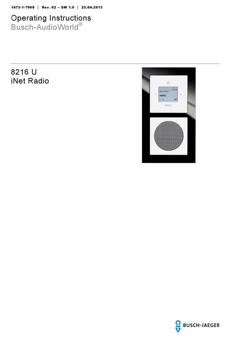
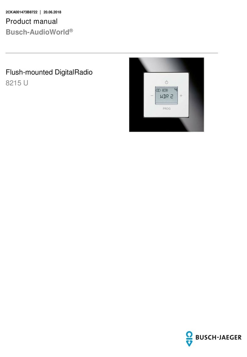
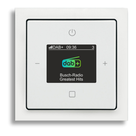
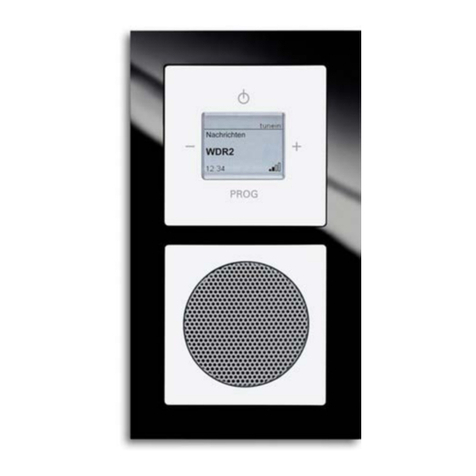
Busch-Jaeger Busch-AudioWorld 8215 U-101 User manual

Product manual │08.12.2021
Busch-AudioWorld
®
8215 U-101
Busch-Radio DAB+

Table of contents
Product manual 2CKA001473B5162
│
2
Table of contents
1
Notes on the instruction manual....................................................................................................................4
2
Safety.............................................................................................................................................................5
2.1
Introduction.........................................................................................................................................5
2.2
Information and symbols used...........................................................................................................5
2.3
Intended use ......................................................................................................................................6
2.4
Improper use ......................................................................................................................................6
2.5
Target group / Qualifications of personnel.........................................................................................7
2.5.1
Operation ..................................................................................................................................... 7
2.5.2
Installation, commissioning and maintenance .............................................................................. 7
2.6
Safety instructions..............................................................................................................................8
3
Information on protection of the environment ...............................................................................................9
3.1
Environment .......................................................................................................................................9
4
Setup and function.......................................................................................................................................10
4.1
Functions..........................................................................................................................................10
4.2
Possible combinations .....................................................................................................................11
5
Technical data .............................................................................................................................................12
6
Connection, installation / mounting .............................................................................................................13
6.1
Safety ...............................................................................................................................................13
6.2
Requirements for the electrician ......................................................................................................13
6.3
Mounting / dismantling .....................................................................................................................14
6.4
Electrical connection ........................................................................................................................19
6.5
Multimedia connection .....................................................................................................................20
6.5.1
Loudspeaker .............................................................................................................................. 20
6.5.2
AUX (Auxiliary)........................................................................................................................... 21
6.5.3
Antenna...................................................................................................................................... 23
7
Commissioning ............................................................................................................................................24
8
Operation .....................................................................................................................................................26
8.1
Operating modes..............................................................................................................................26
8.2
Normal operation..............................................................................................................................28
8.2.1
Overview .................................................................................................................................... 28
8.2.2
Button assignment...................................................................................................................... 29
8.2.3
Adjusting the volume .................................................................................................................. 30
8.2.4
Selecting the station (Favourites) ............................................................................................... 30
8.2.5
Operating alarm clock / snooze function..................................................................................... 32
8.2.6
Sleep function (turn-off time) ...................................................................................................... 35
8.2.7
Display favourites (favourite stations)......................................................................................... 36
8.2.8
Save favourites (favourite stations) ............................................................................................ 36
8.2.9
Operating AUX ........................................................................................................................... 37
8.2.10
Voltage failure ............................................................................................................................ 39
8.3
Operation - Configuration.................................................................................................................40
8.3.1
Display ....................................................................................................................................... 40

Table of contents
Product manual 2CKA001473B5162
│
3
8.3.2
Button assignment...................................................................................................................... 41
8.3.3
Functions - Configuration ........................................................................................................... 42
8.3.4
Menu "Alarm clock" - "Alarm clock" ............................................................................................ 44
8.3.5
Menu "Alarm clock" - "Alarm profiles"......................................................................................... 45
8.3.6
Menu "Alarm clock" "Alarm times".............................................................................................. 46
8.3.7
Menu "Alarm clock" "Deactivate days" ....................................................................................... 48
8.3.8
Menu "Alarm clock" – "Specifying "Signal tones"........................................................................ 49
8.3.9
Menu "Station" "Display station list DAB+ " and save favourites ................................................ 50
8.3.10
Menu "Station" "Display station list FM" and save favourites...................................................... 51
8.3.11
Menu "Stations" - "Automatic search mode DAB+" .................................................................... 52
8.3.12
Menu "Stations" - "Automatic search mode for FM stations" ...................................................... 53
8.3.13
Menu "Station" – "Setting FM stations manually" ....................................................................... 54
8.3.14
Menu "Station" - "Move favourites"............................................................................................. 55
8.3.15
Menu "Station" - "Delete favourites" ........................................................................................... 56
8.3.16
Menu "Settings" - "Language" .................................................................................................... 57
8.3.17
Menu "Settings -"Bass" .............................................................................................................. 60
8.3.18
Menu "Settings" - "Treble" .......................................................................................................... 61
8.3.19
Menu "Settings" - "Start volume" ................................................................................................ 62
8.3.20
Menu "Settings - "Maximum volume" ......................................................................................... 63
8.3.21
Menu "Settings" - "AUX"............................................................................................................. 64
8.3.22
Menu "Settings" – "AUX input gain"............................................................................................ 65
8.3.23
Menu "Settings" - "Display profile".............................................................................................. 66
8.3.24
Menu "Settings" - "Display illumination"...................................................................................... 67
8.3.25
Menu "Settings" - "Display brightness" ....................................................................................... 68
8.3.26
Menu "Settings" - "Sleep timer" (switch-off time) ........................................................................ 69
8.3.27
Menu "Settings" – "Energy efficiency" ........................................................................................ 70
8.3.28
Menu "Settings" - "Extension unit operation" .............................................................................. 71
8.3.29
Menu "Settings" - "Antenna"....................................................................................................... 72
8.3.30
Menu "Settings" - "Hotel mode".................................................................................................. 73
8.3.31
Menu "Info"................................................................................................................................. 75
8.3.32
Menu tree ................................................................................................................................... 76
8.3.33
RESET (resetting to the factory settings) ................................................................................... 79
9
Case studies ................................................................................................................................................80
9.1
Installation set ..................................................................................................................................80
9.2
Installation set and extension unit operation ...................................................................................82
9.3
Installation set and movement detectors .........................................................................................84
9.4
Ceiling loudspeakers........................................................................................................................87
9.5
AUX and amplifier ............................................................................................................................88
9.6
AUX and HiFi system .......................................................................................................................90
9.7
AUX and TV audio signals ...............................................................................................................92
10
Maintenance ................................................................................................................................................94
10.1
Cleaning ...........................................................................................................................................94
11
FAQ and tips ................................................................................................................................................95
12
Index ............................................................................................................................................................97
Notes on the instruction manual
Product manual 2CKA001473B5162
│
4
1 Notes on the instruction manual
Please read through this manual carefully and observe the information it contains. This will
assist you in preventing injuries and damage to property, and ensure both reliable operation and
a long service life for the device.
Please keep this manual in a safe place.
If you pass the device on, also pass on this manual along with it.
Busch-Jaeger accepts no liability for any failure to observe the instructions in this manual.
If you require additional information or have questions about the device, please contact Busch-
Jaeger or visit our Internet site at:
www.BUSCH-JAEGER.de

Safety
Product manual 2CKA001473B5162
│
5
2 Safety
2.1 Introduction
The device has been constructed according to the latest valid regulations governing technology
and is operationally reliable. It has been tested and left the factory in a technically safe and
reliable state.
However, residual hazards remain. Read and adhere to the safety instructions to prevent
hazards of this kind.
Busch-Jaeger accepts no liability for any failure to observe the safety instructions.
2.2 Information and symbols used
The following Instructions point to particular hazards involved in the use of the device or provide
practical instructions:
Danger
Risk of death / serious damage to health
– The respective warning symbol in connection with the signal word "Danger"
indicates an imminently threatening danger which leads to death or serious
(irreversible) injuries.
Warning
Serious damage to health
– The respective warning symbol in connection with the signal word "Warning"
indicates a threatening danger which can lead to death or serious
(irreversible) injuries.
Caution
Damage to health
– The respective warning symbol in connection with the signal word "Caution"
indicates a danger which can lead to minor (reversible) injuries.
Attention
Damage to property
– This symbol in connection with the signal word "Attention" indicates a
situation which could cause damage to the product itself or to objects in its
surroundings.
NOTE
This symbol in connection with the word "Note" indicates useful tips and
recommendations for the efficient handling of the product.
This symbol alerts to electric voltage.

Safety
Product manual 2CKA001473B5162
│
6
2.3 Intended use
This device is a radio for flush-mounted installation.
The device is intended for the following:
■Operation according to the listed technical data,
■Installation in dry interior rooms and suitable flush-mounted boxes,
■Use with the connecting options available on the device.
The intended use also includes adherence to all specifications in this manual.
2.4 Improper use
Each use not listed in Chapter 2.3 “Intended use“ on page 6 is deemed improper use and can
lead to personal injury and damage to property.
Busch-Jaeger is not liable for damages caused by use deemed contrary to the intended use of
the device. The associated risk is borne exclusively by the user/operator.
The device is not intended for the following:
■Unauthorized structural changes
■Repairs
■Outdoor use
■The use in bathroom areas

Safety
Product manual 2CKA001473B5162
│
7
2.5 Target group / Qualifications of personnel
2.5.1 Operation
No special qualifications are needed to operate the device.
2.5.2 Installation, commissioning and maintenance
Installation, commissioning and maintenance of the device must only be carried out by trained
and properly qualified electrical installers.
The electrical installer must have read and understood the manual and follow the instructions
provided.
The electrical installer must adhere to the valid national regulations in his/her country governing
the installation, functional test, repair and maintenance of electrical products.
The electrical installer must be familiar with and correctly apply the "five safety rules" (DIN VDE
0105, EN 50110):
1. Disconnect
2. Secure against being re-connected
3. Ensure there is no voltage
4. Connect to earth and short-circuit
5. Cover or barricade adjacent live parts

Safety
Product manual 2CKA001473B5162
│
8
2.6 Safety instructions
Danger - Electric voltage!
Electric voltage! Risk of death and fire due to electric voltage of 100 … 240 V.
Dangerous currents flow through the body when coming into direct or indirect
contact with live components. This can result in electric shock, burns or even
death.
■Work on the 100 … 240 V supply system may only be performed by
authorised and qualified electricians.
■Disconnect the mains power supply before installation / disassembly.
■Never use the device with damaged connecting cables.
■Do not open covers firmly bolted to the housing of the device.
■Use the device only in a technically faultless state.
■Do not make changes to or perform repairs on the device, on its components
or its accessories.
■Keep the device away from water and wet surroundings.
Caution! - Risk of damaging the device due to external factors!
Moisture and contamination can damage the device.
■Protect the device against humidity, dirt and damage during transport,
storage and operation.

Information on protection of the environment
Product manual 2CKA001473B5162
│
9
3 Information on protection of the environment
3.1 Environment
Consider the protection of the environment!
Used electric and electronic devices must not be disposed of with domestic
waste.
– The device contains valuable raw materials which can be recycled.
Therefore, dispose of the device at the appropriate collecting depot.
All packaging materials and devices bear the markings and test seals for proper disposal.
Always dispose of the packaging material and electric devices and their components via the
authorized collecting depots and disposal companies.
The products meet the legal requirements, in particular the laws governing electronic and
electrical devices and the REACH ordinance.
(EU Directive 2012/19/EU WEEE and 2011/65/EU RoHS)
(EU REACH ordinance and law for the implementation of the ordinance (EC) No.1907/2006).

Setup and function
Product manual 2CKA001473B5162
│
10
4 Setup and function
4.1 Functions
The device is a functional radio with various setting options and is installed flush-mounted in the
wall. The device offers you the following, for example:
■An AUX interface for music replay from external devices or for sending music to external
devices.
■A memory for up to 8 favourites (favourite stations).
■Receiving from DAB+ stations.
■Receiving from FM stations.
■Time and date display.
■An alarm call function.
■A sleep function.

Setup and function
Product manual 2CKA001473B5162
│
11
4.2 Possible combinations
8215 U-101
8223 U X
8222 EB X
8224 EB X
8225 EB X
8226 EB X
8226/10 EB X
8252-xxx-101 X
Table 1: Possible combinations
Notice
Connection of loudspeakers, see chapter 6.5.1 “Loudspeaker“ on page 20.

Technical data
Product manual 2CKA001473B5162
│
12
5 Technical data
Designation Value
Nominal voltage: 230 V AC, ±10%, 50 / 60 Hz
Display
■Colour display
■Visual range horizontal / vertical: +/- 80 °
Power consumption during the idle state
■ECO mode: ≤0.4 W
■Comfort mode: ≤5 W
Output power of loudspeaker: 2 x 2 W (RMS)
Conductor cross section of screw-type terminals,
for power supply:
0.2 to 2.5 mm²,
AWG 14 to 26
Skinning length of screw-type terminals, for power
supply: 6 mm
Conductor cross-section of push-in terminal,
Loudspeaker/signal connection/antenna terminals
rigid/flexible:
0.2 to 1.5 mm²,
AWG 16 to 24
Skinning length of loudspeaker/signal
connection/antenna terminals: 8 mm
Admissible loudspeaker impedance: 4 to 8 Ω
Frequency range of audio: 250 to 15,000 Hz
Frequency range: of FM: 87.5 to 108 MHz
Frequency range of DAB+: 174 to 240 MHz
Temperature range: 5 – +40°C
Storage temperature: -20 – +70°C
Protection type: IP 20
Table 2: Technical data

Connection, installation / mounting
Product manual 2CKA001473B5162
│
13
6 Connection, installation / mounting
6.1 Safety
Danger - Electric voltage!
Risk of death due to electrical voltage of 100 … 240 V during short-circuit in the
low-voltage conduit.
– Low-voltage and 100 … 240 V conduits must not be installed together in a
flush-mounted box!
Attention! - antenna signal is too weak!
If the antenna signal is too weak at the mounting location planned for the device,
it will be difficult or impossible to adjust the radio stations later.
– Before starting work, check whether the antenna signal is strong enough at
the location planned for the installation of the device.
– If in doubt, select a different mounting location, or connect an external
antenna..
6.2 Requirements for the electrician
Danger - Electric voltage!
Install the device only if you have the necessary electrical engineering
knowledge and experience.
■Incorrect installation endangers your life and that of the user of the electrical
system.
■Incorrect installation can cause serious damage to property, e.g. due to fire.
The minimum necessary expert knowledge and requirements for the installation
are as follows:
■Apply the "five safety rules" (DIN VDE 0105, EN 50110):
1. Disconnect
2. Secure against being re-connected
3. Ensure there is no voltage
4. Connect to earth and short-circuit
5. Cover or barricade adjacent live parts.
■Use suitable personal protective clothing.
■Use only suitable tools and measuring devices.
■Check the type of supply network (TN system, IT system, TT system) to
secure the following power supply conditions (classic connection to ground,
protective earthing, necessary additional measures, etc.).

Connection, installation / mounting
Product manual 2CKA001473B5162
│
14
6.3 Mounting / dismantling
Caution! The device can sustain damage when coming into contact with
hard objects!
The plastic parts of the device are sensitive.
– Pull the attachment off only with your hands.
– Do not lever parts off with screwdrivers or similar hard objects.
Hinweis
Elektronische Geräte mit integriertem Schaltnetzteil können im Einzelfall
Empfangsstörungen verursachen, wenn diese in unmittelbarer Nähe zum Radio
montiert werden.
The flush-mounted insert must only be installed in flush-mounted boxes according to DIN
49073, Part 1, or suitable surface-mounted housings.
Mounting
To install the device, perform the following steps:
Fig. 1: Wall mounting: pulling off the attachment
1. Pull the attachment off.
– If the device is already mounted or assembled, pull the attachment off the flush-mounted
insert with the aid of the cover frame.

Connection, installation / mounting
Product manual 2CKA001473B5162
│
15
TOP
Fig. 2: Device in as-delivered state: pulling off the attachment
– If the device is in its as-delivered state, pull the attachment off the flush-mounted insert
with your hands.
– Pull the attachment off only with your hands!
– Do not lever parts off with screwdrivers or similar hard objects. This will damage the
device.
– When pulling off, first the resistance of the spring clamps must be overcome.
Fig. 3: Connection of loudspeaker cables / signal lines
2. Connect the loudspeaker cables and signal lines to the flush-mounted insert.
– Both connecting terminals are plug-in terminals.
– For the connection assignment, see chapter 6.4 “Electrical connection“ on page 19.
– The following options are available for connecting the plug-in terminals:
■Loudspeaker (for more detailed information see chapter 6.5.1 “Loudspeaker“ on
page 20)
■AUX input / AUX output (for more detailed information see chapter 6.5.2 “AUX
(Auxiliary)“ on page 21)
■Antenna (for more detailed information see chapter 6.5.3 “Antenna“ on page 23)

Connection, installation / mounting
Product manual 2CKA001473B5162
│
16
Fig. 4: Connecting the power supply cable
3. Connect the mains cables to the flush-mounted insert.
– Both connecting terminals are screw-type terminals.
– Screw-type terminals (max. 3.5 Lb-In, 0.4 Nm)
– For the connection assignment, see chapter 6.4 “Electrical connection“ on page 19.
Fig. 5: Mounting the flush-mounted insert
4. Mount the flush-mounted insert.

Connection, installation / mounting
Product manual 2CKA001473B5162
│
17
TOP
Fig. 6: Mounting the display
5. Plug the attachment together with the cover frame onto the flush-mounted insert.
– Ensure that the plug-in connection on the rear side does not get jammed.
– The arrow (TOP) must point upwards when plugging it.
– If mounting is difficult, check whether a burr has formed at the lock-in openings of the
flush-mounted insert and remove it.
The device is now mounted.

Connection, installation / mounting
Product manual 2CKA001473B5162
│
18
Dismantling
To dismantle the device, perform the following steps:
Dismantling is carried out in the reverse order to mounting.
Fig. 7: Loosening the plug-in terminals
■Loosen the plug-in terminals of the loudspeaker cables and signal lines on the flush-
mounted insert with the aid of a screwdriver.
– Press the terminal fixture into the device and pull the cable out.

Connection, installation / mounting
Product manual 2CKA001473B5162
│
19
6.4 Electrical connection
Note
An automatic circuit breaker must be available in the building installation.
– Automatic circuit breaker: 110 - 230 V AC, ±10%, 50 / 60 Hz max. B16A.
– Local regulations for electrical installations must be adhered to.
L
N
16A
L1N
L L RRRL
AUX
IN/OUT
CB D
A
Fig. 8: Electrical connection
[A] Option: AUX terminals configured as input or output, see chapter 8.3.21 “Menu "Settings" -
"AUX"“ on page 64.
[B] Option: connection of an external antenna, see chapter 6.5.3 “Antenna“ on page 23.
[C] Option: simultaneous switch-on with room light.
[D] Variation: When connecting fluorescent lamps, energy-saving lamps or LED lamps, a 2-pole
switch is recommended.

Connection, installation / mounting
Product manual 2CKA001473B5162
│
20
6.5 Multimedia connection
6.5.1 Loudspeaker
MONO operation
L1N
L L RRRL
AUX
IN/OUT
Fig. 9: Loudspeaker connection MONO
For MONO operation, the loudspeaker can be connected to the left (L+ / L-) or right (R+ / R-)
connecting terminals.
– Observe the polarity of the connections when connecting the loudspeakers.
STEREO operation
L1N
L L RRRL
AUX
IN/OUT
Fig. 10: Loudspeaker connection STEREO
For STEREO operation, two loudspeakers can be connected, one to the left (L+ / L-) and one to
the right (R+ / R-) connecting terminal.
– Observe the polarity of the connections when connecting the loudspeakers.
Table of contents
Other Busch-Jaeger Radio manuals

Busch-Jaeger
Busch-Jaeger Busch-AudioWorld 8217 U-101 User manual

Busch-Jaeger
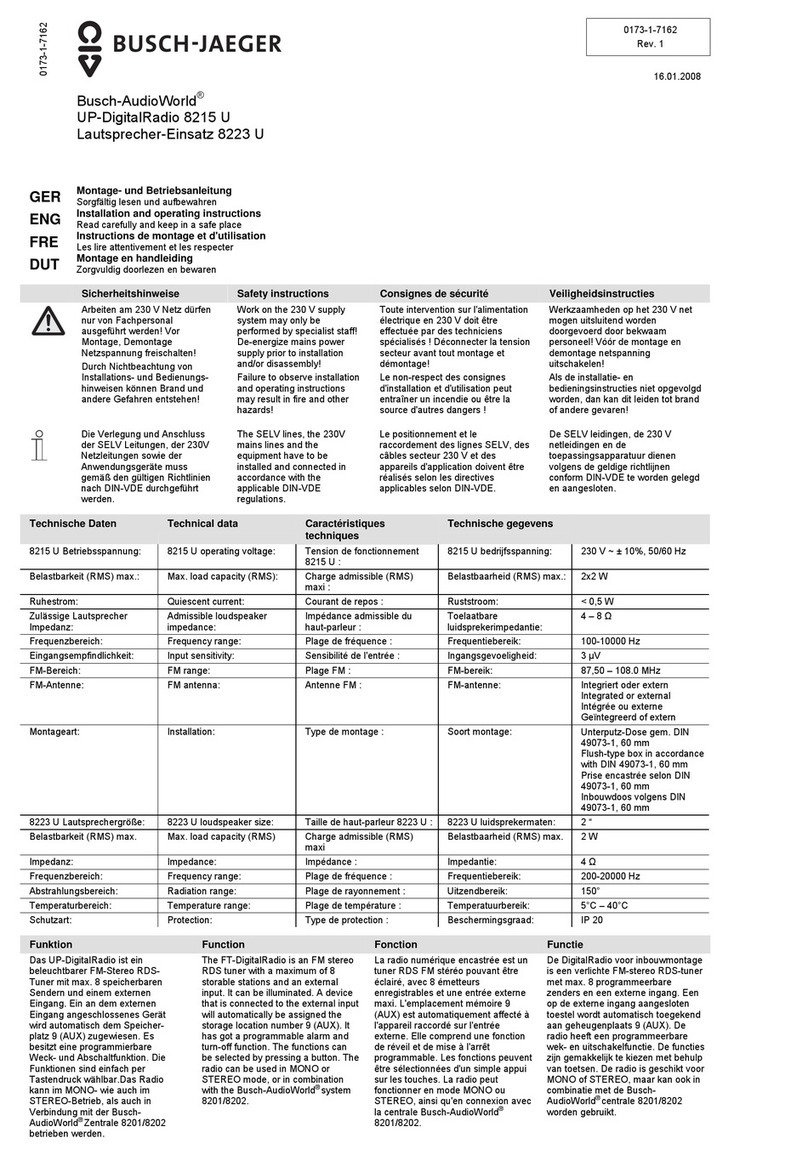
Busch-Jaeger AudioWorld 8215 U User manual

Busch-Jaeger
Busch-Jaeger AudioWorld 8216 U User manual

Busch-Jaeger
Busch-Jaeger Busch-AudioWorld 8216 U Busch-Radio iNet User manual

Busch-Jaeger
Busch-Jaeger AudioWorld 8215 U User manual