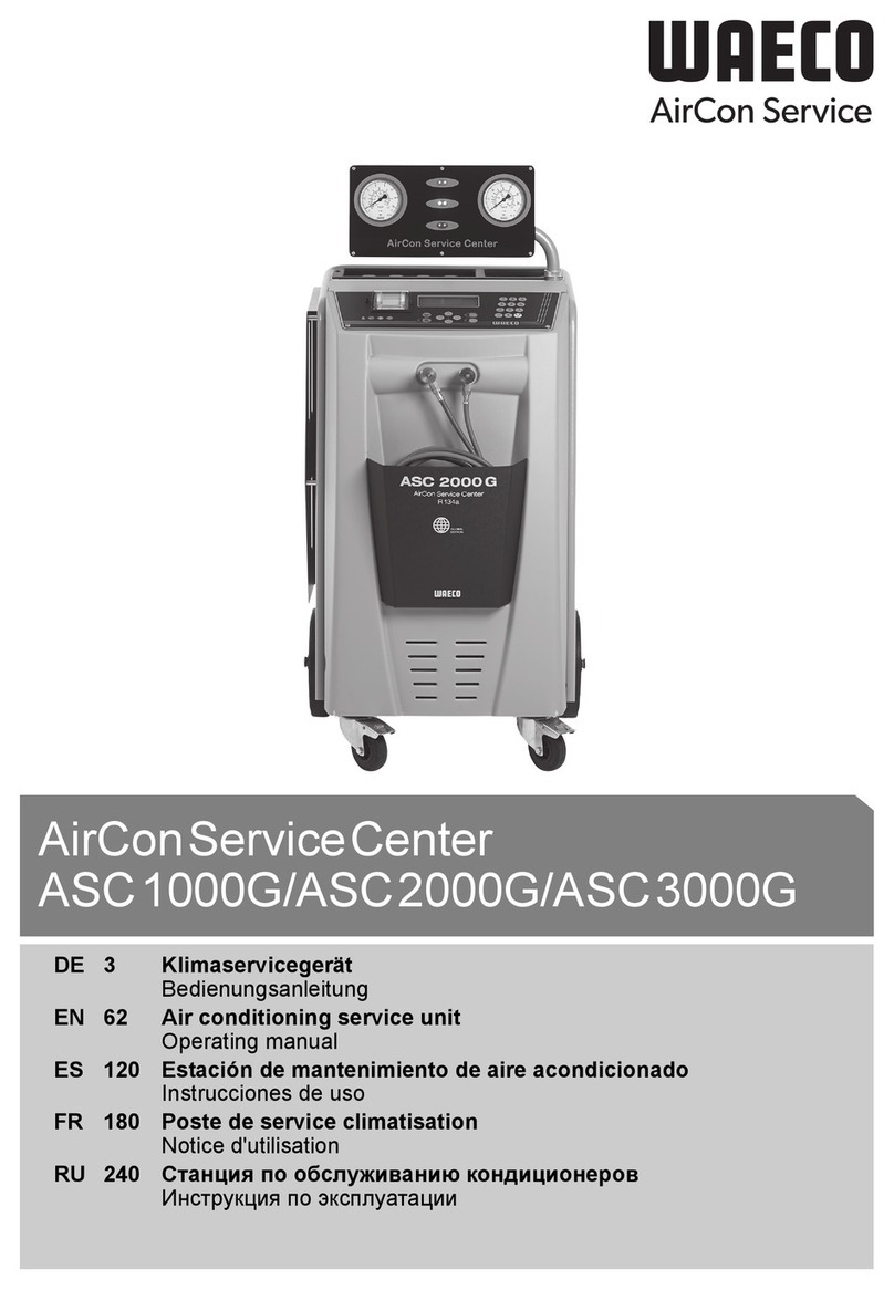
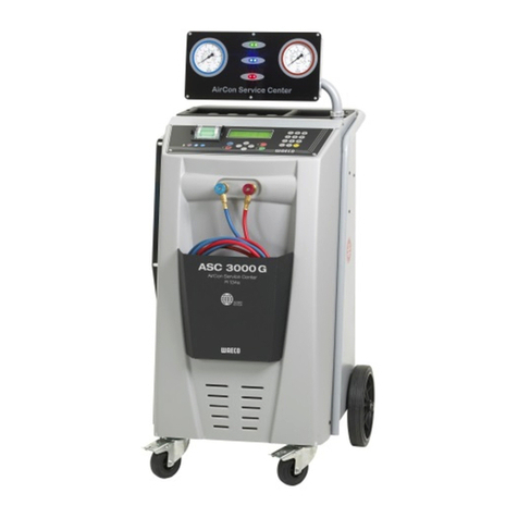
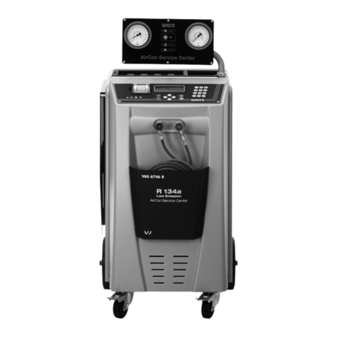
Waeco ASC 6300 G LE User manual

ASC 6300 G LE, ASC 6400 G LE
EN A/C service unit
Operating manual.......................................................3
FR Poste de service climatisation
Manuel d’utilisation................................................... 51
DE Klimaservicegerät
Bedienungsanleitung............................................... 101
RU Станция по обслуживанию кондиционеров
Инструкция по эксплуатации....................................151
ES Estación de mantenimiento de aire
acondicionado
Instrucciones de uso................................................201

Copyright
© 2022 Dometic Group. The visual appearance of the contents of this manual is protected by copyright and de-
sign law. The underlying technical design and the products contained herein may be protected by design, patent
or be patent pending. The trademarks mentioned in this manual belong to Dometic Sweden AB. All rights are re-
served.

EN
English
Original instructions
1Important notes.............................................................................................................................................. 3
2About the manual...........................................................................................................................................3
3Target Group.................................................................................................................................................. 3
4Hotline.............................................................................................................................................................4
5Explanation of symbols..................................................................................................................................4
6Safety instructions..........................................................................................................................................4
7Scope of Delivery...........................................................................................................................................6
8Accessories.................................................................................................................................................... 6
9Intended use.................................................................................................................................................. 6
10 Technical description......................................................................................................................................7
11 Overview of the A/C service unit...................................................................................................................8
12 Initial start-up................................................................................................................................................10
13 Operation......................................................................................................................................................17
14 Service tasks................................................................................................................................................28
15 Troubleshooting............................................................................................................................................ 36
16 Disposal........................................................................................................................................................38
17 Technical Data..............................................................................................................................................39
1 Important notes
Please read these instructions carefully and follow all instructions, guidelines, and warnings included in this product manual in order to ensure that you install, use, and maintain the product properly at all
times. These instructions MUST stay with this product.
By using the product, you hereby confirm that you have read all instructions, guidelines, and warnings carefully and that you understand and agree to abide by the terms and conditions as set forth here-
in. You agree to use this product only for the intended purpose and application and in accordance with the instructions, guidelines, and warnings as set forth in this product manual as well as in accordance
with all applicable laws and regulations. A failure to read and follow the instructions and warnings set forth herein may result in an injury to yourself and others, damage to your product or damage to other
property in the vicinity. This product manual, including the instructions, guidelines, and warnings, and related documentation, may be subject to changes and updates. For up-to-date product information,
please visit documents.dometic.com.
2 About the manual
This operating manual describes A/C service units.
It contains all the instructions necessary for safe and effective operation of the A/C service unit. Before starting
the A/C service unit for the first time, read this operating manual carefully.
Note the information in the current material safety data sheets. They can be found at: dometic.com/sds
Keep this operating manual in the compartment of the A/C service unit, so that any information you need is al-
ways at hand.
Find this manual in other languages online on documents.dometic.com/search/?
query=4445103552.
3 Target Group
Only people that have proven understanding to identify and avoid the hazards involved may operate and maintain
the A/C service unit. This knowledge maybe gathered by any appropriate training or supervision.
3

EN
4 Hotline
If you need more information on the A/C service unit that is not contained in this manual, please contact the hot-
line: Tel.: +49 (0) 2572 879-0
5 Explanation of symbols
WARNING! Safety instruction: Indicates a hazardous situation that, if not avoided, could result in death or
serious injury.
CAUTION! Safety instruction: Indicates a hazardous situation that, if not avoided, could result in minor or
moderate injury.
NOTICE! Indicates a situation that, if not avoided, can result in property damage.
Note Supplementary information for operating the product.
6 Safety instructions
WARNING! Failure to obey these warnings could result in death or serious injury.
•Observe national work safety regulations.
•Observe the safety instructions in this operating manual.
•The A/C service unit may only be used by personnel who are able to demonstrate the appropriate spe-
cialist training and are familiar with the operation and basic principles of the A/C service unit, of air
conditioning systems and of refrigerants.
•The A/C service unit may only be repaired by personnel authorized by Dometic.
•Only use the device for its intended purpose.
CAUTION! Failure to obey these cautions could result in minor or moderate injury.
•Do not make modifications to the A/C service unit.
•Risk of injury from bursting components if the permitted temperature limits are exceeded: Only trans-
port the A/C service unit without refrigerant to avoid excess pressure.
•The A/C service unit may not be stored outdoors.
•Store the service hoses in the hose pocket when the A/C service unit is not in use.
6.1 Operating the device safely
WARNING! Failure to obey these warnings could result in death or serious injury.
•Do not operate the A/C service unit in areas where there is a risk of explosion (for example, battery
charging rooms or spraying booths). Operate only according the respective national health and safety
regulations.
•Do not pump compressed air into the refrigerant lines of the A/C service unit or the vehicle air condi-
tioning system. A mixture of compressed air and refrigerant can be flammable or explosive.
• Risk of injury due to unplanned or unintended switching on of the A/C service unit: Switch off
the A/C service unit prior to all maintenance work and disconnect the mains cable from the mains sup-
ply. Pull the plug from the socket or from the A/C service unit.
• Risk of burns from cold or hot components: Wear protective gloves.
4

EN
CAUTION! Failure to obey these cautions could result in minor or moderate injury.
•Do not start up the A/C service unit if it is damaged.
•Each time you start up or top up the A/C service unit, first check whether the A/C service unit and all
the service hoses are undamaged and that all valves are closed.
•Lay the service hoses in such a way that they pose no tripping hazard for other persons.
• Serious injuries due to overturning or falling load: The handle is not used to lift the A/C service
unit. Only push the A/C service unit on rollers to transport it.
•Always position the A/C service unit on level ground and secure the front wheels.
•Only use approved refrigerant vessels with safety valves to refill the A/C service unit.
•Always use the main switch of the A/C service unit to switch it on and off. Do not leave the device un-
attended when it is switched on.
• Risk of injury from leaking fluids: Leaking fluids on the floor can cause persons to slip and injure
themselves. Wipe up leaked or dripped fluids immediately or absorb them with a suitable binding
agent. Dispose of them in an environmentally sound manner.
NOTICE! Indicates a situation that, if not avoided, can result in property damage.
•Never expose the A/C service unit to heavy moisture.
•Do not operate the A/C service unit outdoors when it is raining.
•Do not operate the A/C service unit near heat sources (such as heaters) or in direct sunlight.
•Only use the refrigerant that you have set in the A/C service unit. If other refrigerants are mixed in, this
can damage the A/C service unit and the vehicle air conditioning system.
•Before you shut down the A/C service unit, make sure that the selected program has ended and that
all valves are shut. Otherwise refrigerant can leak.
•When you modify values in the menus, always compare them with the specifications on the vehicle.
•When parking, use the brake lever on the front wheels to secure the A/C service unit from rolling away.
6.2 Handling the refrigerant safely
WARNING! Failure to obey these warnings could result in death or serious injury.
Do not carry out maintenance work on the vehicle air conditioning system when the engine is at operating
temperature. When performing maintenance on the vehicle air conditioner, the surface temperature of at-
tachment parts or surrounding parts must be less than the refrigerant's flashpoint:
R1234yf: 405 °C
R134a: 743 °C
R153A: not applicable
CAUTION! Failure to obey these cautions could result in minor or moderate injury.
•Wear personal safety equipment (safety goggles and protective gloves) and avoid coming into con-
tact with the refrigerant. Contact with the refrigerant draws out body heat and the affected areas can
freeze.
•Do not inhale refrigerant vapor. Although the vapor is non-toxic, it displaces the oxygen you need to
breathe.
•Only use the device in well-ventilated areas.
•Refrigerant may not be used in low-lying spaces such as assembly pits or soakaways. Refrigerant is
heavier than oxygen and therefore displaces the air you need to breathe. This can cause a lack of oxy-
gen when working in unventilated assembly pits.
NOTICE! Indicates a situation that, if not avoided, can result in property damage.
•Make sure that refrigerant is not able to escape and leak into the environment during operation, when
filling or draining refrigerant or during repair and service work. This will protect the environment. It also
avoids the difficulty or impossibility of detecting leaks in the vehicle or in the A/C service unit due to the
presence of refrigerant in the vicinity of the A/C service unit.
•Take suitable precautions to ensure that leaking refrigerant is not able to get into the drainage system.
Note Supplementary information for operating the product.
Special information on the refrigerant and safety measures as well as the protection of personnel and ob-
jects, including fire protection, can be found in the safety sheets of the refrigerant manufacturer.
5

EN
6.3 Safety measures by the operator
The operator must provide operating instructions according to respective national regulations for each A/C service
unit. These operating instructions must be used to train personnel in handling the A/C service unit.
The operator must ensure that personnel are instructed in the following points at least once a year:
•Special dangers when dealing with compressed gases
•Safety guidelines when dealing with compressed gases
•Health precautions when dealing with compressed gases
•Operating the A/C service unit and performing service work on the A/C service unit
The operator must ensure that personnel appointed to perform service and repair work as well as leak inspections
are certified to deal with refrigerant and filling systems.
Certification and knowledge of the applicable guidelines and standards can be acquired from a training course at
a chamber of trade, chamber of industry and commerce or at any other recognized training facility.
The system operator must ensure that all service hoses are laid in such a way that they cannot be damaged when
the A/C service unit is used.
7 Scope of Delivery
The A/C service unit was tested for leaks before shipping.
After delivery, check that all the parts listed below are present and undamaged.
If any parts are missing or damaged, notify the company responsible for transport immediately.
Description Ref. no.
Goggles/gloves 4445900107
Protective unit cover 4445900081
Operating manual 4445103552
NOTICE! Damage hazard
•For safe operation and calibration a refrigerant (R1234yf, R134a, R513A; not in scope of delivery) is
required.
•Refrigerant vessels are supplied with various connecting threads and adapters; these are not in the
scope of delivery.
8 Accessories
Available as accessories (not included in the scope of delivery):
Description Ref. no.
Replacement filter for R134a, R153A 4440400009
Replacement filter for R1234yf 4445900221
Spare printer roll (thermal paper) (4 pieces) 4445900088
Vacuum pump oil (1000 ml) 8887200018
9 Intended use
The A/C service unit is intended for performing maintenance on vehicle air conditioning systems. The A/C service
unit is intended for commercial use.
The A/C service unit may only be used to service vehicle air conditioning systems in which one of the following re-
frigerants is used:
•R1234yf
•R134a
•R513A
6

EN
The A/C service unit is only suitable for approved operating fluids.
This product is only suitable for the intended purpose and application in accordance with these instructions.
This manual provides information that is necessary for proper installation and/or operation of the product. Poor in-
stallation and/or improper operating or maintenance will result in unsatisfactory performance and a possible fail-
ure.
The manufacturer accepts no liability for any injury or damage to the product resulting from:
•Incorrect assembly or connection, including excess voltage
•Incorrect maintenance or use of spare parts other than original spare parts provided by the manufacturer
•Alterations to the product without express permission from the manufacturer
•Use for purposes other than those described in this manual
Dometic reserves the right to change product appearance and product specifications.
10 Technical description
10.1 Warnings on the A/C service unit
Observe the operating manual.
Only connect the A/C service unit to an AC socket with 230 V / 240 V, 50 Hz / 60 Hz (see Technical
Data on page 39).
Protect the A/C service unit against rain.
Wear gloves when handling refrigerants.
Wear goggles when handling refrigerants.
10.2 Safety devices
•Pressure monitor: Switches the compressor off if normal operating pressure is exceeded.
•Pressure relief valves: Additional safety mechanism to protect lines or vessels from bursting if the pressure
continues to rise despite the safety pressure monitor.
•Fan monitor: Checks the fans work properly at start-up.
10.3 Standby menu
The standby menu shows the following information:
•Refrigerant quantity
•Fresh oil quantity
•UV additive quantity
•Time
•Date
10.4 Basic menu
The basic menu is the start menu to the following functions:
•Short selection
•Free selection
•Other selections
7

EN
11 Overview of the A/C service unit
1 Low pressure gauge
2 Fill lamp (red)
3 Evacuate lamp (blue)
4 ECO deep emptying lamp (yellow)
5 Suction lamp (green)
6 High pressure gauge
7 Display
8 Keypad
9 Front cover
10 Front wheels with wheel stops
11 Service hose for low pressure connection (blue) (not included inth scope of delivery)
12 Service hose for high pressure connection (red) (not included inth scope of delivery)
13 Service coupling for high pressure connection (red)
14 Service coupling for low pressure connection (blue)
15 Printer
16 USB port
8

EN
17 Container for fresh oil
9

EN
18 Container for UV additive (500 ml)
19 Drained oil receptacle
20 Cover flap
21 Main switch
22 Fan
12 Initial start-up
This chapter describes the procedures you have to carry out before you can operate the A/C service unit.
12.1 Setting up and switching on
Note In order to achieve correct measurements, the A/C service unit must be placed on a level flat sur-
face during operation. Ignore any error codes which occur during commissioning (Troubleshooting on
page 36) and skip by pressing ENTER.
1. Wheel the A/C service unit to the workplace and lock the front wheels.
2. Mount the service hoses.
3. Set the length of the service hoses (Setting the length of the service hoses on page 29).
4. Connect the A/C service unit to the power supply.
5. To switch the A/C service unit on, set the main switch to I.
The switch-on delay runs for 35 s and the housing is ventilated. The software version number then appears in
the display for several seconds:
mgas0081
mgas2107
LE640004
LF
DB
SW
SN000000
LE
ASC6400G
Dometic Germany GmbH
SW:
Software status
DB:
Database
SN:
Serial number
LF:
Language file
6. Once the start-up procedure is complete, the A/C service unit requires the selection of the refrigerant (Select-
ing the refrigerant on page 10).
12.2 Selecting the refrigerant
On initial start-up the A/C service unit displays the refrigerant selection menu.
1. In the refrigerant selection menu use the cursor keys or to select the desired refrigerant (in the following
example R153A).
R-513A
R-1234yf
R-134a
Refrigerant
10

EN
2. Press ENTER to confirm.
The chosen refrigerant is displayed.
No
Yes
ENTER-OK
R-513A
Refrigerant
Confirm
3. Press ENTER to confirm the selection and follow the instructions in the display and provided here:
ENTER-OK
Once done, press OK.
connection hose!
Please install HP/LP
4. Install the HP/LP connection hoses.
5. Press ENTER to confirm.
Wait !
The service hoses are evacuated.
6. Wait until the service hoses are evacuated.
7. Press ENTER to confirm the displayed refrigerant:
ENTER-OK
R - 513A !
Usage only with
WARNING !
The A/C service unit runs a cleaning phase of the internal vessel pressure.
pressure mb.
Internal vessel
Cleaning phase.
Afterwards the A/C service unit runs a software test.
Don't connect to
Software test.
Please wait!
the A/C system yet!
Afterwards the A/C service unit displays the Standby menu:
Refrigerant g. XXXX
PAG oil ml XXX
UV tracer ml XXX
11:56:35 10/03/17
12.3 Selecting the language
1. Press the cursor keys or .
2. In the basic menu use the cursor keys or to select Other selections.
Short selection
Free selection
Other selections
ENTER-OK
3. Press ENTER to confirm.
11

EN
4. Use the cursor key to select Service.
5. Press ENTER to confirm.
6. Enter the password 5264.
7. Use the cursor keys or to select the preferred language.
8. Press ENTER to confirm.
9. Press STOP.
The language chosen is active and the standby menu is displayed.
12.4 Setting the font
1. Press the cursor keys or to acces the basic menu.
2. In the basic menu use the cursor keys or to select Other selections.
Short selection
Free selection
Other selections
ENTER-OK
3. Press ENTER to confirm.
4. Use the cursor key to select Service.
5. Press ENTER to confirm.
6. Enter the password 3667.
PAR FONT
Mingliu
Unifont
ENTER-OK
7. Use the cursor keys or to select the desired font.
•Unifont
•Mingliu
8. Press ENTER to confirm.
9. Press STOP.
The font chosen is active and the standby menu is displayed.
12.5 Setting the buzzer volume
1. Press the cursor keys or to acces the basic menu.
2. In the basic menu use the cursor keys or to select Other selections.
Short selection
Free selection
Other selections
ENTER-OK
3. Press ENTER to confirm.
4. Use the cursor key to select Service.
5. Press ENTER to confirm.
6. Enter the password 2899.
PAR Buzzer
Loud
Quiet
ENTER-OK
7. Use the cursor keys or to select the desired volume.
8. Press ENTER to confirm.
12

EN
9. Press STOP.
The volume chosen is active and the standby menu is displayed.
12.6 Entering the company data
The company data is printed out with every service log.
1. In the basic menu use the cursor keys or to select Other selections.
Short selection
Free selection
Other selections
ENTER-OK
2. Press ENTER to confirm.
3. Use the cursor key to select Service.
4. Press ENTER to confirm.
5. Enter the password 3282.
The company data is shown in the third line of the display.
You can enter five lines, each with up to 20 characters.
The display shows the number of lines of company data after the message Enter company data (01 to 05).
Use the cursor keys or to select the line of company data you want.
6. Use the keypad and the cursor keys to enter the data. To switch between upper and lower case, press the
key. To delete a character, briefly press the C key. To delete the current line, press and hold down the C
key.
7. Press ENTER to confirm.
8. Press STOP.
The set data is activated.
9. Press STOP again.
The standby menu is displayed.
12.7 Entering the date and time
Date and time are required for logging of the service procedures. The date and the time are printed along with the
company data on every service log.
1. In the basic menu use the cursor keys or to select Other selections.
Short selection
Free selection
Other selections
ENTER-OK
2. Press ENTER to confirm.
3. Use the cursor key to select Service.
4. Press ENTER to confirm.
5. Enter the password 8463.
6. Use the keypad and the cursor keys to enter the information.
7. Press ENTER to confirm.
8. Press STOP.
The standby menu is displayed.
12.8 Editing default values
The A/C service unit has preset values for the most important service tasks. The default values appear
automatically when you select the respective menu.
You can alter the following default values if necessary:
13

EN
Parameter Default value
Pressure increase test time min. 1
Vacuum time min. 1
Leak test min. 4
PAG oil ml. (additional quantity) 0
UV tracer ml. 0
Filling Qt. g. 500
Display logo? Yes
1. In the basic menu use the cursor keys or to select Other selections.
Short selection
Free selection
Other selections
ENTER-OK
2. Press ENTER to confirm.
3. Use the cursor key to select Service.
4. Press ENTER to confirm.
5. Enter the password 7388.
6. Use the keypad and the cursor keys to enter the information.
7. Press ENTER to confirm.
8. Press STOP.
The standby menu is displayed.
12.9 Inserting the containers for oil and UV additive
NOTICE! Damage hazard
Only use oils approved for the corresponding refrigerant. Observe the manufacturer's instructions.
The current supply quantities are displayed in the standby menu.
14

EN
1. Open the cover flap (20) on the left side and push the containers into the snap locks:
•Container for fresh oil (17)
•Container for UV additive (18)
•Drained oil receptacle (19)
2. Close the cover flap (20).
3. Enter the container size for fresh oil and UV contrast agent (Entering the container size on page 15).
12.10 Entering the container size
Fresh oil and UV contrast agent can be kept in containers of 150 ml (A), 250 ml (B) or 500 ml(C) (accessories).
You must enter the size of the container in the A/C service unit.
15

EN
1. In the basic menu use the cursor keys or to select Other selections.
Short selection
Free selection
Other selections
ENTER-OK
2. Press ENTER to confirm.
3. Use the cursor key to select Service.
Refrigerant Test
Hybrid service
Service.
ENTER-OK STOP-EXIT
4. Press ENTER to confirm.
5. Enter the password 2688.
6. Use the cursor keys to activate any fields you need (dark fields are activated).
Oil bottle
150ml 250ml 500ml
UV bottle
150ml 250ml 500ml
7. Press ENTER to confirm.
8. Press STOP to access the standby menu..
12.11 Filling up the internal refrigerant container
When the A/C service unit is started for the first time, the A/C service unit displays Error 12, because the inter-
nal refrigerant vessel must be filled from an external refrigerant vessel with at least 2000 g of refrigerant.
1. Press STOP to confirm.
The current supply quantities are displayed in the standby menu.
2. Connect the external refrigerant vessel to the A/C service unit.
Note Observe the instructions on the refrigerant vessels. Vessels for the R1234yf refrigerant have a
left-hand thread.
There are three different types of refrigerant vessel available:
•Refrigerant vessels without rising pipe: These refrigerant vessels have one connection. When filling the A/
C service unit, the connection must be on the bottom (turn the vessel upside down).
•Refrigerant vessels with rising pipe: These refrigerant vessels have one connection. When filling the A/C
service unit, the connection must be at the top (place the vessel upright).
•Refrigerant vessels with rising pipe: These refrigerant vessels have two connections. To top up the A/C
service unit, use the connection marked with L (= liquid). When filling the A/C service unit, the connection
must be at the top (place the vessel upright).
3. In the basic menu use the cursor keys or to select Other selections.
Short selection
Free selection
Other selections
ENTER-OK
4. Press ENTER to confirm.
5. Use the cursor keys or to select Int. vessel filling.
Int. vessel filling
Flushing
Reset scales.
Service.
16

EN
6. Press ENTER to confirm and follow the instructions in the display and provided here:
Connect the HP hose
to the external tank
then open the valve
ENTER-OK STOP-EXIT
7. Press ENTER to confirm.
Set the quantity,
then confirm!
g. 13620
ENTER-OK STOP-EXIT
The maximum refrigerant quantity which can be added appears in the display.
8. Enter the required amount and press ENTER to confirm.
The internal refrigerant vessel is filled.
When the filling process is finished, this will be confirmed by an acoustic signal.
9. Close the valves and press ENTER to confirm.
After filling, the quantity of refrigerant in the internal container is displayed.
10. Press STOP to exit the menu.
11. Press STOP again to access the standby menu.
12. Disconnect the external refrigerant vessel from the A/C service unit.
The A/C service unit is now ready for operation.
13 Operation
NOTICE! Damage hazard
When the air conditioning system is being serviced, the engine and the A/C service unit must be switched
off.
Note
The A/C service unit is only suitable for 230 V / 240 V (see Technical Data on page 39).
13.1 Shutdown in case of repair, emergencies and malfunctions
1. To ensure that the device is disconnected from the power supply for repairs, switch it off using the main switch
and also pull out the power plug.
2. To turn off the A/C service unit in an emergency or malfunction, turn off the main switch.
13.2 Short selection
A fully automatic air conditioning service is started using the Short selection menu. Included is a leak test that
must be carried out before working on the vehicle air conditioner. The vehicle air conditioner is filled with a sam-
ple refrigerant. The pressure in the vehicle air conditioner must remain constant over a period of 5 min. The vehi-
cle air conditioner can only be completely filled if this test has been successfully completed. The sample filling is
then drained and the vehicle air conditioner evacuated. The final filling quantity is completely filled up to ensure
high filling accuracy.You only have to enter the filling quantity as shown on the label in the vehicle.
The following actions are performed automatically in succession in the Short selection menu:
•Extraction of the refrigerant
•Recycling the refrigerant (purity = SAE J 2099)
•Pressure rise test
•Draining the used oil
•Evacuating the system
•Leak test/vacuum check
•Filling with new oil to the required quantity
•Filling with UV additive
•Filling of refrigerant
17

EN
After each process has been performed a service report is printed. Subsequent actions are only initiated once the
preceding action has been completed successfully.
1. Fit the service hoses for the A/C service unit to the vehicle air conditioning system, and open the service cou-
plings.
2. Press the cursor key or to acces the basic menu.
3. In the basic menu use the cursor keys or to select Short selection.
Short selection
Free selection
Other selections
ENTER-OK
4. Press ENTER to confirm.
5. Use the keypad and the cursor keys to enter the vehicle data.
6. Press ENTER to confirm.
7. Enter the refrigerant filling quantity. Use the value shown on the filling quantities sticker in the vehicle and en-
ter it using the keypad and the cursor keys and press ENTER.
8. Use the cursor keys or to select whether the air conditioning system has two connections (high pressure
and low pressure) or only one connection (high pressure or low pressure).
HP/LP PORT
HP PORT
LP PORT
ENTER-OK STOP-EXIT
9. Press ENTER to confirm.
The fully automatic air conditioning service is started.
After the air conditioning service has finished, you will be prompted to disconnect the A/C service unit's service
hoses of from the vehicle air conditioning system.
10. Disconnect the service hoses and press ENTER to confirm.
The service hoses will now be drained. The A/C service unit is then ready for further use.
11. Put the valve caps of the vehicle air conditioning system back on the connections.
13.3 User Codes
It is possible to protect the A/C service unit from unauthorised access using personal user codes. When this func-
tion is activated, the system queries the user code after being switched on, and the A/C service unit cannot be
started without it. Up to 10 different users can be created with individual codes. Users can be created using the
administrator code.
13.3.1 Creating user codes
1. In the basic menu use the cursor keys or to select Other selections.
Short selection
Free selection
Other selections
ENTER-OK
2. Press ENTER to confirm.
3. Use the cursor key to select Service and press ENTER to confirm.
Flushing
Reset scales.
Service.
ENTER-OK STOP-EXIT
18

EN
4. To acces the ADM administrator menu enter the password 9786 and press ENTER to confirm.
Service.
----
5. Enter the administrator code 0000 (default setting) and press ENTER to confirm:
Insert ADM Code
----
Note For security reasons, a new administrator code must be selected each time, but not 0000 as this
will deactivate the entire function.
6. Enter the new administrator code:
ADM AREA
Insert new code
----
7. Confirm the new administrator code:
ADM AREA
Confirm new code
----
8. Use the cursor keys or to select the user.
ADM AREA
User number
1
9. Create the four-digit personal user code. Once a code is created here, the A/C service unit can then only be
operated using this code.
ADM AREA
User number 1
Insert new code
----
10. Confirm the new user code:
ADM AREA
User number
1
Confirm new code
----
Note To switch between upper and lower case use the yellow Info key.
19

EN
11. Enter the user name and press ENTER to confirm:
ADM AREA
User number
1
User name
John Citizen
ADM AREA
User number 1
John Citizen
The user is created and the menu changes again to the user selection.
12. Proceed as follows:
•Create another user by using the cursor keys to select Database and proceed as described.
•To exit the menu press STOP.
13.3.2 Entering user codes
If a user code has been created, the same code must be used to enable the A/C service unit.
Enter the user code.
ENTER USER CODE
----
If you enter an incorrect user code, the following error message appears:
WRONG CODE
Once the correct code is entered, the A/C service unit is enabled and starts up. The user's name is displayed:
John Citizen
13.4 Creating a personal database
You can enter up to 100 customer-specific vehicles with the corresponding filling quantities in this database. The
personal entries are saved in the control board, not on the flash memory card. The entries will be retained even
after updating the software. The entries are stored chronologically, not alphanumerically.
1. In the basic menu use the cursor keys or to select Short selection.
Short selection
Free selection
Other selections
ENTER-OK
2. Press ENTER to confirm.
3. Enter the vehicle license plate number (this can also be left blank) and press ENTER to confirm.
CAR DATA
PLATE NR:
20
This manual suits for next models
3
Table of contents
Languages:
Other Waeco Service Equipment manuals

Waeco
Waeco VAS 6380B User manual

Waeco
Waeco ASC5500G RPA User manual

Waeco
Waeco AirCon Service Center BMW 2500G User manual

Waeco
Waeco AirConServiceCenter ASC1000G User manual

Waeco
Waeco AirCon Service OZ1000 User manual

Waeco
Waeco AirCon Service 6300G User manual

Waeco
Waeco AirCon Service Center VAS 581 001A User manual

Waeco
Waeco ASC2300G User manual

Waeco
Waeco AirConServiceCenter VAS 6746B User manual

Waeco
Waeco ASC 6300 G User manual