INSTRUCTION MANUAL
CHARGERS FOR FREE ELECTROLYTE LEAD BATTERIES
CAUTIONS
•During battery charging explosive gases could occur, therefore avoid the formation of sparks or flames. NO
SMOKING.
•Carry out charging only inside ventilated places. Do not expose to rain or snow.
•In battery-chargers equipped with parts such as switches or relays, electric arcs or sparks can be caused; therefore,
when used in garages or similar places, place the battery charger in a room or in a case suitable for isolation from
explosive gases.
•In Class I models (equipped with earth terminal) to guarantee protection against indirect contacts make sure the
power mains outlet has an earth contact.
•Make sure the battery charger is disconnected from the power outlet before connecting or disconnecting the
charging leads to the battery.
•Avoid contact between the output terminals.
• Do not use the battery charger inside the car or the bonnet.
• Do not touch the liquid inside the battery as it is corrosive.
•Do not charge depleted or damaged batteries, or batteries other than those given above.
•Improper use of the battery charger or any tampering with the electrical circuit inside the appliance will invalidate
the warranty.
•Any repairs or maintenance on the appliance must only be carried out by specialized personnel.
CHARGING
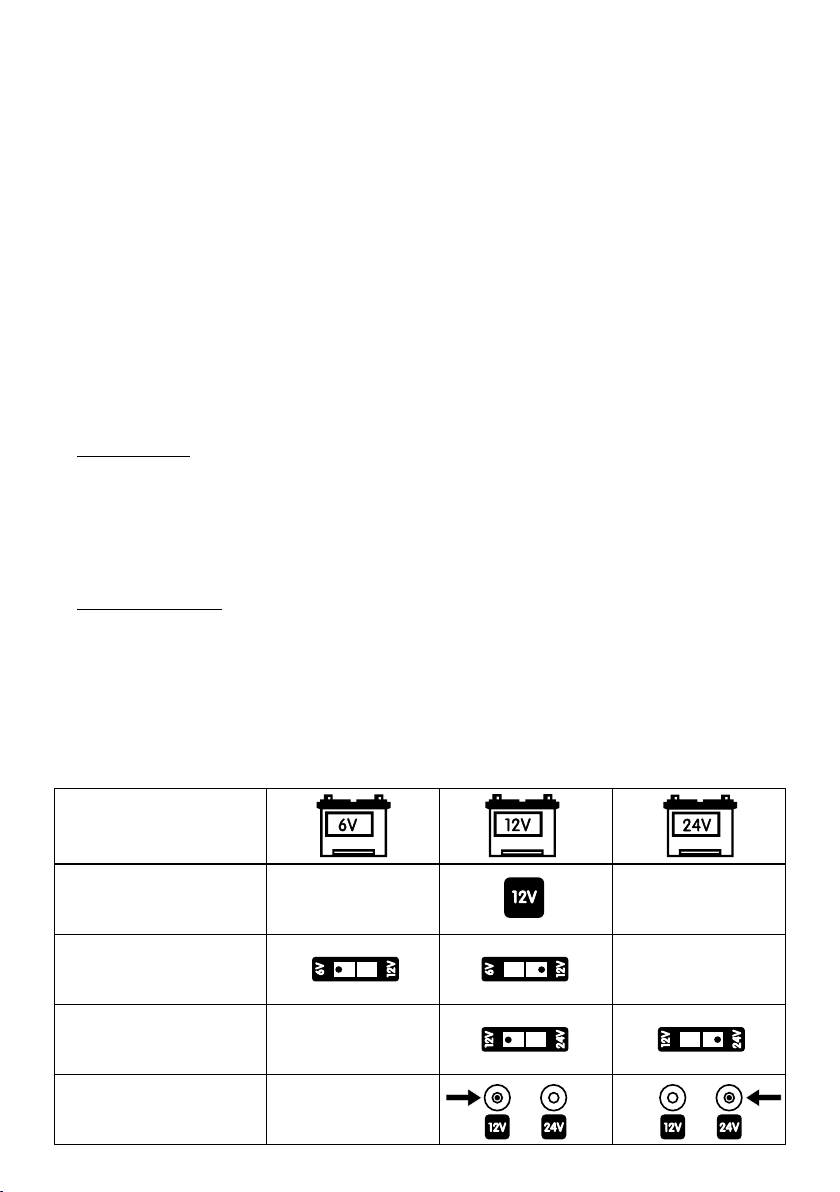
The battery charger will only charge free-electrolyte lead batteries having the following number of elements: 3 for 6-
volt batteries, 6 for 12-volt batteries, 12 for 24-volt batteries.
A) Before charging, check the state of the battery.
1. Remove the caps or the special fasteners of the battery.
2. Make sure the electrolyte level covers the battery plates; otherwise add distilled water until they are covered by 5/
10 mm.
3. The exact state of the battery can only be determined with a densimeter which measures the specific density of the
electrolyte. Battery charge conditions can be checked according to the following solute density values (Kg/l at
20°C):
1.28 battery charged - 1.21 battery half-charged - 1.15 battery flat.
B) Proceed with charging, by carrying out the following steps and in the same order:
1. Before charging, make sure the feed cable is disconnected from the mains power supply.
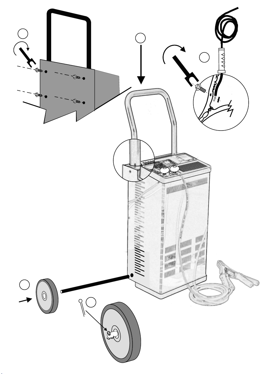
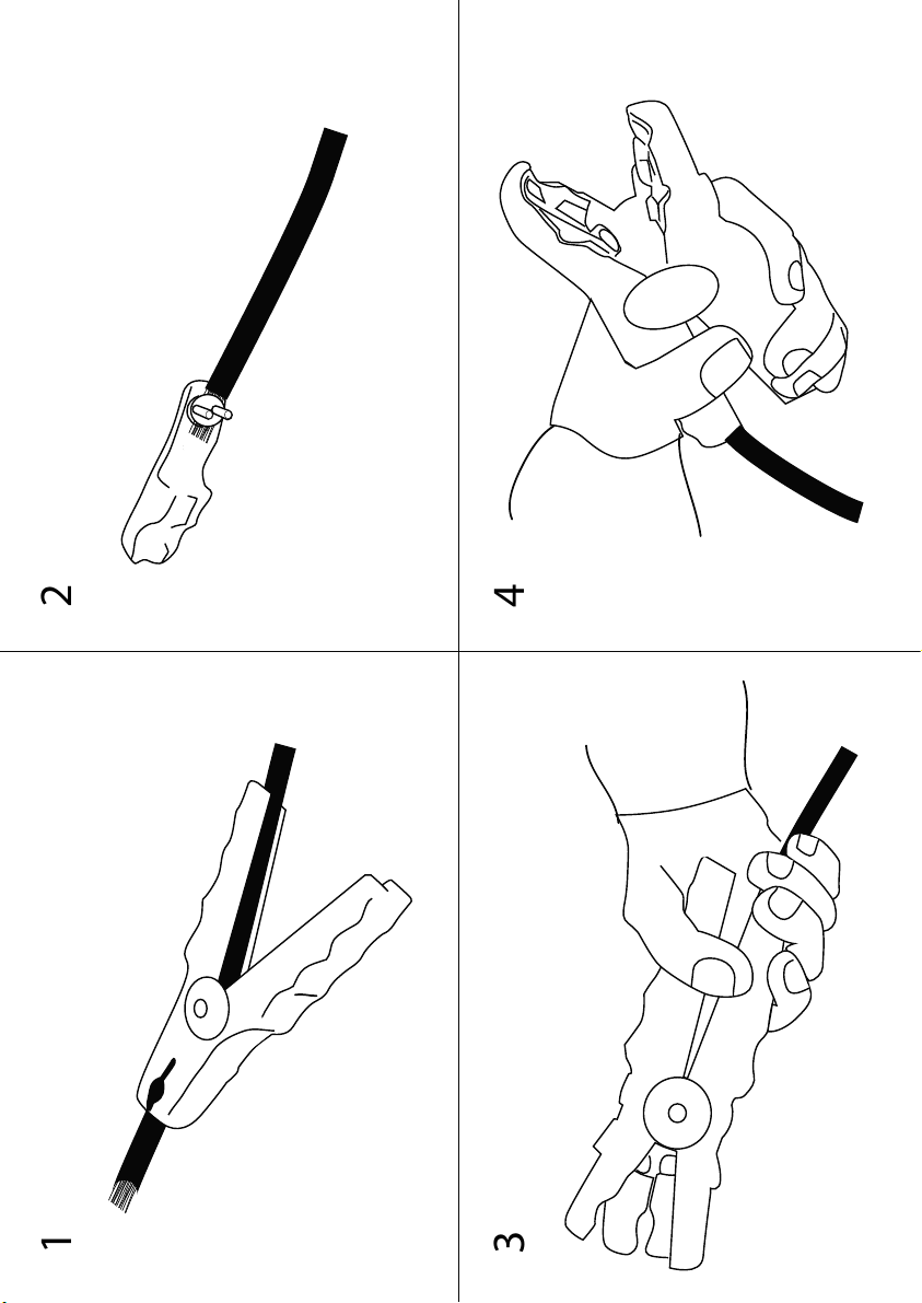
2. Connect the red clamp and the black clamp to the terminals of the relative output leads. Fig. 7
3. Switch to the voltage 6/12V (if present) or 12/24V (if present) according to the nominal voltage of the battery being
charged. Fig. 1.
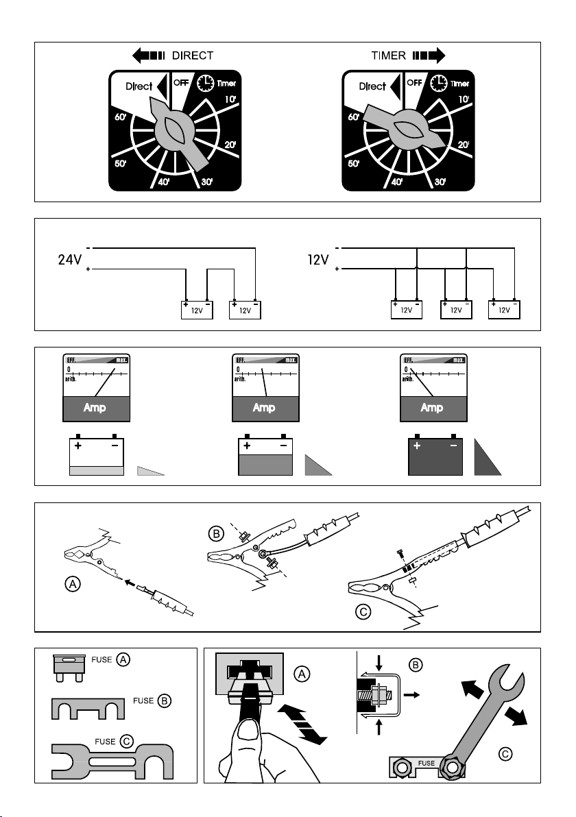
* Note: To charge several batteries at the same time see the series/parallel diagram in Fig. 5
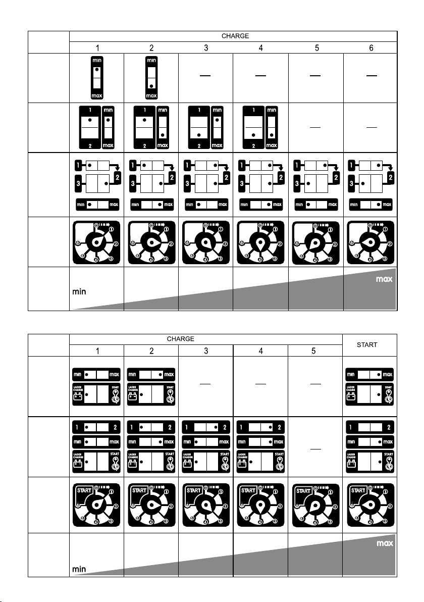
4. Position the current adjustment diverters (if present) according to the instructions in Fig. 2. In models with TIMER
a timed charge can be carried out by rotating the timer knob clockwise until reaching the desired charge time Fig. 4
* Note: It is always a good rule to carry out charging by adjusting the current to one tenth the battery’s nominal
capacity for approximately 10/15 hours. For small capacity batteries adjust the current to minimum and let charge
for no more than 4/5 hours.
5. Connect the output wire with red clamp to the positive terminal (+) of the battery.
6. Connect the other output wire with black clamp to the negative terminal (-) of the battery, or in case of direct charge,
connect it directly to the vehicle’s chassis at a good distance from the battery or from the fuel pipe.
7. Connect the feed cable plug to the mains, making sure the voltage matches the nominal voltage of the battery
charger. Turn the switch to “ON” (if present).
If everything is correctly connected the needle shift of the ammeter (present on the battery charger) will indicate the
initial charging current.
* Note: If the battery charger is adjusted to a minimum current level and is connected to an almost fully-charged
battery, the ammeter needle shift could be imperceptible or even absent.
While the battery is charging the current decreases slowly according to the characteristic curve W in accordance
with standard DIN41774, the instrument needle goes to very low values (approaching 0), the battery charged state.
Fig. 6
8. Turn the switch (if present) to “OFF”, and/or disconnect the feed cable from the mains power outlet.
9. Disconnect the output leads in this order: the clamp from the vehicle’s chassis or negative pole (-), the clamp from
the positive pole (+) of the battery.
10. Close the battery cells with the caps or the special fasteners.
11. Store the battery charger in a dry place.
GB
Fig. 4
Fig. 5
Fig. 6
Fig. 7
Fig. 9
Fig. 8
Connection of batteries IN SERIES Connection of batteries IN PARALLEL
CHARGE START
EMPTY
DURING CHARGE
HALF
END OF CHARGE
FULL