manuals.online logo
Brands
  1. Home
  2. •
  3. Brands
  4. •
  5. Byron
  6. •
  7. Accessories
  8. •
  9. Byron SX-54 User manual

Byron SX-54 User manual

Locate the keyhole slot on the back of the unit over
the screw.
Important: Mounting the Converter unit on the
UPVC doorframes or metal surface will
reduce the broadcasting range seriously.
2.Then use the second hole located at the bottom half
of the Converter as a template, mark the fixing
position for the unit. Drill hole and fit wall plug and
secure the Converter unit with the screw (self-tapping
N3 x 16mm screw) in position.
3. Alternatively, use the double-sided self-adhesive pad
(included) to attach the Converter to the fixing position between the bell push and
door chime unit.
c) Door Chime Unit: It has a slotted hang hole on the rear, this will enable the Chime
unit to be hooked onto a screw and easily removed or relocated to another room.
Drill hole and fit wall plug (if fixing to masonry) and screw (self-tapping N3 x 16mm
screw) to fixing position.Leave a gap of 3mm between the screw head and the wall.
Locate the keyhole slot on the back of the unit over the screw.
UM-2
“C”
R14
UM-2
“C”
R14
UM-2
“C”
R14
UM-2
“C”
R14
UM-2
“C”
R14
UM-2
“C”
R14
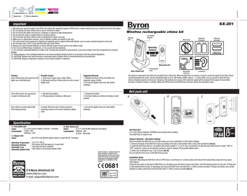
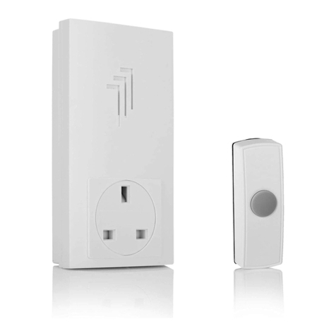
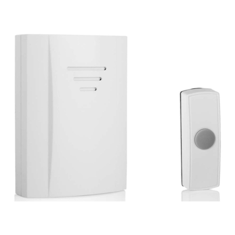
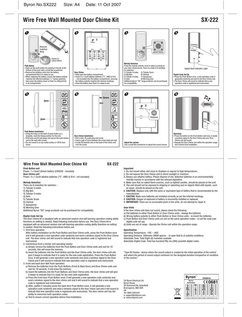
The Wire Free Door Chime Kit consists of three separate units:
1.Wired Push Button unit
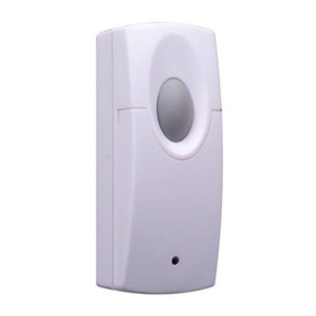
2. Converter (Transmitter)
3. Door Chime unit (Receiver)
When the Push Button is pressed, it sends a
wirefree signal to the door chime that activates
the chime.As the operating range is up to 100
metres (320 ft. approx.), you can mount or take
the door chime virtually anywhere in the home.
However, the transmission range of the wirefree
signal will be reduced if the signal is transmitter
through a number of walls or ceilings. Metal, and
UPVC doorframes will also reduce the operating range.
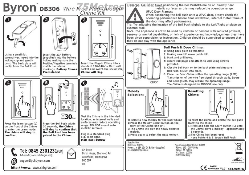
Battery Installation
Wire Free Converter
1.The Converter unit is operated by 1 x 12 volt battery
(A23 - included).
2. Remove the back of the case by pushing in the tab on the
bottom with a small, flat screwdriver.
3. Insert 1 x 12 volt battery (A23 - included) in the battery
compartment, ensuring the battery polarity match the internal
markings.
4. Snap the front cover of Converter back on, then it is ready to use.
Door Chime unit
1. Remove the front cover.
2. Insert 3 x 1.5 volt (“C”, UM2 & R14 - not included) alkaline batteries
into the battery compartment, ensuring the battery polarity match the
internal markings.
3. Snap the front cover back on, the chime unit is ready to use.
Installation Guide
a)Wired Bell Push: Using the two holes of the back of push button
as a template, mark the fixing position for the unit. Drill hole and
fit wall plug and secure the Push Button Unit with screws (self-
tapping 3 x 16mm screw) in position onto your front door or the position nearby.
b) Converter:
1. Drill hole and fit wall plug (if fixing to masonry) and screws (self-tapping N3 x 16mm
screw) to fixing position.Leave a gap of 3mm between the screw head and the wall.
Wiring Installation
The Converter is designed to change your new Wired Bell Push to wirefree.
1. Simply connect your Wired Bell Push with the cable from Converter to the terminals
on your bell push.
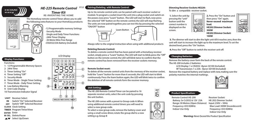
Channel Selection
The unit comes from the factory on a pre-set radio frequency digital code.However,
should your door chime activate intermittently for no reason at all, it is possible that a
similar unit is operating nearby on the same frequency digital code.The encoded
frequency of the Converter (transmitter) and Door Chime (receiver) can be changed to
avoid this problem.
1. Converter: Remove the back of the case by pushing in the tab on the bottom with a
small, flat screwdriver.
Door Chime Unit: Remove the front cover.
2.There is 4 position dip switch marked 1,2,3 & 4. Use an insulated tool to alter the dip
switch levers to the “On” or “Off” position, which can be altered to achieve a total of
sixteen (16) possible channels.
3. Select any combination ensuring it is set to the same code on both converter and
door chime units.E.g. If the 1 & 2 dipswitches are down in your converter, then the 1
& 2 dipswitches must be down in your chime unit.
4.Test to ensure correct operation before final installation.
Important
1. Do not mount the Converter unit onto any metal or UPVC doorframes, as this will
reduce the operating range.
2. Do not immerse either unit in water.
3. Do not mount either unit close to fireplace or expose to high temperature.
4. Do not use different type of batteries, or mix up old and new batteries.
5. Do not leave exhausted batteries in either unit. If leaving the doorbell for long
period, remove the battery from compartments to prevent leakage.
2.Your Wired Bell Push with Converter is ready to use.
In case a Transformer (A/C 8V) is used to power the Wired Bell Push and Wired Door
Chime.
1. Remove the back of the case by pushing in the tab on the bottom with a small, flat
screwdriver.
2. Disconnect the wire that is connected with the Wired Door Chime.
3. Feed the wire via the hole on the back of the Converter, connect the wire to the
terminal positions marked in diagrams below.
4. Snap the front cover of converter back on, then it is ready to use.
Important: Do not connect the Converter unit with any Lighted Bell Push.
SX
Chime
unit
WIRED
CHIME
(Transformer
operation)
4
T
Converter
unit
SX
Chime
unit
WIRED
CHIME
(Transformer
operation)
3
T
Converter
unit
SX
Chime
unit
1
Converter
unit SX
Chime
unit
WIRED
CHIME
(Battery
operation)
2
Converter
unit
B+C SWITCH
A+C 8V/AC
B+C SWITCH
Wired Bell
Push
Converter unit
Please note that these diagrams are only for
reference as a guide.
EachWired Chime can be wired differently, so
if you encounter problems, PLEASE CALL THE
HELPLINE NO. 0121 5449499
6. Always use alkaline batteries as these will give longer service and less likely to leak.
7.The Converter and Door Chime units are designed for indoor use only.
8. Please dispose of old, defective batteries in an environmentally friendly manner in
accordance with the relevant legislation.
9. Make sure that no naked flame sources, such as lighted candles, should be placed on
the unit.
10.The unit should not be exposed to dripping or splashing and that no objects filled
with liquids, such as vases, shall be placed on the unit.
11. CAUTION: Replace only with the same or equivalent type of battery that are
recommended by the manufacturer.
12. CAUTION: Danger of explosion if battery is incorrectly installed or replaced.
Trouble Shooting & User Hints
Problem
Chime does not
sound but LED
lights on Converter
Possible Causes
1. Units are out of range
(max. range 100m)
2. Conterter and Chime units
are not on the same digital
code
3. Converter not wired correctly
Suggested Remedy
1. Operate the Chime unit within
the operation range (100m)
2. Re-set the digital code
(see Digital Code Set Up)
3. See wiring diagrams opposite
Chime does not
sound plus no
lights on Conterter
LED
1. Flat Converter battery
2.Wrong polarity of battery in
Converter
1. Change the battery
2. Re-insert battery as internal
marking in right polarity
Chime sounds
without Converter
being pressed
A similar Wire Free Door
Chime product is operating nearby
on the same frequency
digital code
Re-set the digital code
(see Digital Code Set Up)
NOTE: There are no serviceable parts in the unit, do not attempt to repair it.
Specification
A. Converter unit
Power
Consumption : 1 x 12 volt battery (“A23” - included. Replace with Byron SD-100 model)
: 3.0mA - ON
0.003mA - OFF
B. Door Chime unit
Power
Consumption
Operating Temperature
Operating Distance
Selectable Digital Code
: 3 x 1.5volt batteries (“C”, UM2 or R14 - not included)
: 100mA - ON
0.1mA - Stand-by
: -10°C to +40°C
: 100 metres (320 feet approx.) in open field
:Total sixteen (16) possible digital codes
Wire Free Door Chime Kit with Converter-SX-54

Other Byron Accessories manuals

Byron BY212 Owner's manual

Byron

Byron BY212 Owner's manual

Byron Home Easy HE-207 User manual

Byron

Byron Home Easy HE-207 User manual

Byron SX-86 Owner's manual

Byron

Byron SX-86 Owner's manual

Byron Home Easy HE-303 User manual

Byron

Byron Home Easy HE-303 User manual

Byron SX-202 User manual

Byron

Byron SX-202 User manual

Byron BY202 Owner's manual

Byron

Byron BY202 Owner's manual

Byron SX-80 Owner's manual

Byron

Byron SX-80 Owner's manual

Byron SX83 Owner's manual

Byron

Byron SX83 Owner's manual

Byron Home Easy HE-302 User manual

Byron

Byron Home Easy HE-302 User manual

Byron DB333 Owner's manual

Byron

Byron DB333 Owner's manual

Byron DB305 Owner's manual

Byron

Byron DB305 Owner's manual

Byron BY103 Owner's manual

Byron

Byron BY103 Owner's manual

Byron DB421E-F User manual

Byron

Byron DB421E-F User manual

Byron SX303 User manual

Byron

Byron SX303 User manual

Byron Home Easy HE-301 User manual

Byron

Byron Home Easy HE-301 User manual

Byron 2204BN User manual

Byron

Byron 2204BN User manual

Byron Home Easy HE-304 User manual

Byron

Byron Home Easy HE-304 User manual

Byron SX-205B Owner's manual

Byron

Byron SX-205B Owner's manual

Byron SX-38BN Owner's manual

Byron

Byron SX-38BN Owner's manual

Byron Home Easy HE-202 User manual

Byron

Byron Home Easy HE-202 User manual

Byron Home Easy HE-306 User manual

Byron

Byron Home Easy HE-306 User manual

Byron Home Easy HE-209 User manual

Byron

Byron Home Easy HE-209 User manual

Byron BY201F Owner's manual

Byron

Byron BY201F Owner's manual

Byron SX-4i Owner's manual

Byron

Byron SX-4i Owner's manual

Popular Accessories manuals by other brands

Hugo Brennenstuhl 802U-2-5V operating instructions

Hugo Brennenstuhl

Hugo Brennenstuhl 802U-2-5V operating instructions

LST GSA-45681-200 Specification sheet

LST

LST GSA-45681-200 Specification sheet

Laser PB-2200LED quick start guide

Laser

Laser PB-2200LED quick start guide

elsner elektronik KNX AQS/TH-B-UP Technical specifications and installation instructions

elsner elektronik

elsner elektronik KNX AQS/TH-B-UP Technical specifications and installation instructions

Sirius Connect SCVDOC1 SiriusConnect user guide

Sirius Connect

Sirius Connect SCVDOC1 SiriusConnect user guide

DoCash M user manual

DoCash

DoCash M user manual

OTIS OI-675 Operation manual

OTIS

OTIS OI-675 Operation manual

VACHERON CONSTANTIN ROTATING BOX manual

VACHERON CONSTANTIN

VACHERON CONSTANTIN ROTATING BOX manual

MORDOMUS Meteo-1706 instructions

MORDOMUS

MORDOMUS Meteo-1706 instructions

Aeotec MULTISENSOR 6 user guide

Aeotec

Aeotec MULTISENSOR 6 user guide

Pfeiffer Vacuum RPT 010 operating instructions

Pfeiffer Vacuum

Pfeiffer Vacuum RPT 010 operating instructions

Dedrone RF-360 installation manual

Dedrone

Dedrone RF-360 installation manual

Sygonix 89213w operating instructions

Sygonix

Sygonix 89213w operating instructions

Baumer OHDM 16P5651 quick start guide

Baumer

Baumer OHDM 16P5651 quick start guide

IFM Electronic Efector 100 GM505S operating instructions

IFM Electronic

IFM Electronic Efector 100 GM505S operating instructions

Teac TC-SR(T)-G3 Instructions for use

Teac

Teac TC-SR(T)-G3 Instructions for use

CS Instruments VA 521 instruction manual

CS Instruments

CS Instruments VA 521 instruction manual

ProMinent DULCOTEST CLE 3.1-mA operating instructions

ProMinent

ProMinent DULCOTEST CLE 3.1-mA operating instructions

manuals.online logo
manuals.online logoBrands
  • About & Mission
  • Contact us
  • Privacy Policy
  • Terms and Conditions

Copyright 2025 Manuals.Online. All Rights Reserved.