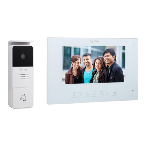
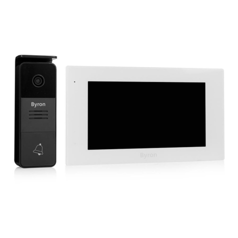
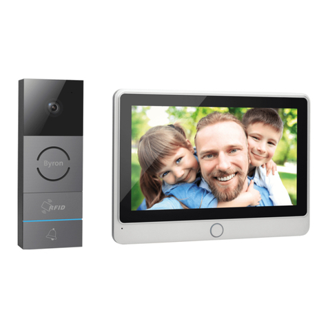
Byron DIC-24122 User manual

DIC-24122

2

DIC-24122
en • 15/07/2019

Table of Contents Byron
iv
Table of Contents
1 Safety ..........................................................................................................................................................................................................6
1.1 Installation Safety...............................................................................................................................................................................6
1.2 Operation Safety ................................................................................................................................................................................6
2 Parts description .......................................................................................................................................................................................6
2.1 What's in the box................................................................................................................................................................................6
2.2 Indoor unit (monitor)...........................................................................................................................................................................6
2.3 Outdoor unit (doorbell) .......................................................................................................................................................................7
3 Installation..................................................................................................................................................................................................7
3.1 Fix the mounting plate of the indoor unit (monitor) ............................................................................................................................7
3.2 Fix the mounting plate of the outdoor unit (doorbell) .........................................................................................................................7
3.3 Electrical installation ..........................................................................................................................................................................7
3.3.1 Connecting the terminal blocks (Indoor and Outdoor unit) ................................................................................................. 7
3.3.2 Mount the indoor units and outdoor unit ............................................................................................................................. 8
3.3.3 Connecting an additional monitor (not included)................................................................................................................. 8
3.3.4 Connecting the AC power ................................................................................................................................................... 8
3.3.5 Connecting a door lock (not included) ................................................................................................................................ 8
3.3.6 Connecting a gate opener (not included)............................................................................................................................ 9
4 Replace call button....................................................................................................................................................................................9
5 Basic functions ..........................................................................................................................................................................................9

Byron Table of Contents
v
5.1 Answering a call.................................................................................................................................................................................9
6 Home screen and menus ..........................................................................................................................................................................9
6.1 Monitor menu .....................................................................................................................................................................................9
6.2 Internal intercom ..............................................................................................................................................................................10
6.3 Recording playback menu ...............................................................................................................................................................10
6.4 Photo menu......................................................................................................................................................................................10
6.5 Settings menu ..................................................................................................................................................................................10
6.5.1 Select photos or video recordings..................................................................................................................................... 10
6.5.2 Video duration................................................................................................................................................................... 10
6.5.3 Number of photos ............................................................................................................................................................. 11
6.5.4 Image settings................................................................................................................................................................... 11
6.5.5 Customer service information ........................................................................................................................................... 11
6.5.6 Formatting MicroSD card\Internal memory ....................................................................................................................... 11
6.5.7 Date and time settings ...................................................................................................................................................... 11
6.5.8 Ringtone and volume ........................................................................................................................................................ 11
7 Frequently asked questions ...................................................................................................................................................................11
8 Specifications ..........................................................................................................................................................................................12
9 Environment.............................................................................................................................................................................................13
10 Declaration of Conformity.......................................................................................................................................................................13

Instruction manual
6
1 Safety
1. Please read these instructions carefully before installing and
using the product.
2. Do not cut the power supply cable to extend it; the device
(transformer) will not work with a longer cable. Do not plug in the
device until all the wiring has been finished.
1.1 INSTALLATION SAFETY
1. Keep children and bystanders away while installing the products.
Distractions can cause you to lose control.
2. Do not overreach when installing this product. Keep proper
footing and balance at all times. This enables better control in
unexpected situations.
3. This product is not a toy. Mount it out of reach of children.
1.2 OPERATION SAFETY
1. Do not operate electrically powered products in explosive
atmospheres, such as in the presence of flammable liquids ,
gases, or dust. Electrically powered products create sparks which
may ignite the dust or fumes.
2. The warnings, precautions, and instructions discussed in this
instruction manual cannot cover all possible conditions and
situations that may occur. It must be understood by the operator
that common sense and caution are factors which cannot be built
into this product, but must be supplied by the operator.
3. Do not expose the Power Adapter of this product to rain or wet
conditions. Water entering the Power Adapter will increase the
risk of electric shock.
4. Do not abuse the Power Cord. Never use the cord for unplugging
the plug from the outlet. Keep cord away from heat, oil, sharp
edges or moving parts. Damaged or entangled cords increase the
risk of electric shock.
5. The adapter must match the outlet. Never modify the plug in any
way. Unmodified plugs and matching outlets will reduce risk of
electric shock.
2 Parts description
2.1 WHAT'S IN THE BOX
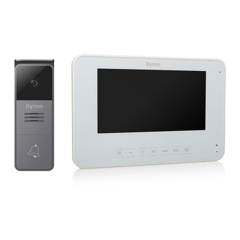
1. Indoor unit (monitor)
2. Outdoor unit (doorbell)
3. Mounting plate outdoor unit (doorbell)
4. Mounting plates monitors
5. AC adapter
6. Additional call button for outdoor unit
7. Cables
8. Terminal blocks
9. Instruction manual
10. Screws and plugs
2.2 INDOOR UNIT (MONITOR)
1. Microphone
2. Home button

Instruction manual
7
3. Touchscreen
4. MicroSD card slot
2.3 OUTDOOR UNIT (DOORBELL)
1. Microphone
2. Camera
3. Speaker
4. Call button (replaceable, extra button included)
5. Call button 2 (replaceable, extra button included)
6. Lock release time switch (On the back of the unit)
3 Installation
3.1 FIX THE MOUNTING PLATE OF THE
INDOOR UNIT (MONITOR)
To mount the monitor, you will need the following tools:
üA suitable screwdriver for the included screws.
üA drill and suitable drill bit for the included screw plugs.
A. Position the provided mounting plate where desired.
B. Mark the screw positions with a pen.
C. Drill the necessary holes.
D. Insert the plugs.
E. Pull the required cables through the mounting plate.
F. Fasten the mounting plate with the screws.
G. Repeat steps a-f for the second monitor.
3.2 FIX THE MOUNTING PLATE OF THE
OUTDOOR UNIT (DOORBELL)
To mount the outdoor unit, you will need the following tools:
üA suitable screwdriver for the included screws.
üA drill and suitable drill bit for the included screw plugs.
A. Position the provided mounting plate where desired.
B. Mark the screw positions with a pen.
C. Drill the necessary holes.
D. Insert the plugs.
E. Use a knife or sharp object to puncture the cable gland.
F. Pull the required cables through the cable gland.
G. Fasten the mounting plate with the screws.
3.3 ELECTRICAL INSTALLATION
3.3.1 Connecting the terminal blocks (Indoor
and Outdoor unit)
There are three terminal blocks included. The GREEN (outdoor unit)
and ORANGE (AC power) terminal blocks are always required. In
case you wish to connect an additional monitor a BLUE terminal
block is also available.
To connect the terminal blocks, you will need the following tool:
üA small flat head screw driver.
A. GREEN terminal block: Loosen the terminal screws.
B. With the terminal facing you, insert the black wire on the left and
the red wire on the right.
EN

Instruction manual
8
C. Fasten the terminal screws.
D. Connect the terminal block(s) to the indoor unit (monitor).
E. Loosen the terminal screws on the outdoor unit (doorbell). (See
sticker on the outdoor unit.)
F. Insert the wires coming from the GREEN terminal block into the
screw terminal on the outdoor unit (doorbell). Indoor unit (Monitor)
1 or 2.
G. Repeat steps a-f to connect the second monitor.
3.3.2 Mount the indoor units and outdoor unit
üA suitable screwdriver for the included screws.
A. Attach the indoor units and outdoor unit to the mounting plates.
B. Fasten the screw at the bottom of the outdoor unit.
3.3.3 Connecting an additional monitor (not
included)
In case you wish to connect an additional monitor to an existing
monitor, a BLUE terminal block is available. This monitor acts as a
repeater to one of the main monitors.
To connect the terminal blocks, you will need the following tool:
üA small flat head screw driver.
A. BLUE terminal block: Loosen the terminal screws.
B. With the terminal facing you, insert the black wire on the left and
the red wire on the right.
C. Fasten the terminal screws.
D. Connect the terminal block to the monitor. (See sticker on the
monitor for position)
E. Repeat steps a-d to fasten an identical terminal block to the other
end of the cable and connecting it to the additional monitor.
3.3.4 Connecting the AC power
To connect the AC terminal blocks, you will need the following tool:
üA small flat head screw driver.
A. ORANGE terminal block: Loosen the terminal screws.
B. With the terminal facing you: Insert the (-) wire on the left and the
(+) wire on the right.
C. Fasten the terminal screws.
D. Connect the terminal block(s) to the monitor.
3.3.5 Connecting a door lock (not included)
It is possible to connect a lock to the outdoor unit that can be opened,
using the monitor. Door locks are sold separately. Article no: DB5005
& DB5005L
To connect the door lock, you will need the following tool:
üA small flat head screw driver.
A. On the outdoor unit: Loosen the terminal screws. (see sticker on
the outdoor unit for position)
B. Insert the wires (any order)
C. Fasten the terminal screws.
D. Set the lock release time by setting switch no 1 on the doorbell.
This will set whether the lock will open for 1 or 4-7 seconds after
opening the lock on the monitor.
Instruction manual
9
E. On the lock: Loosen the 2 terminal screws. (See the manual
provided with your door lock.)
F. Insert the wires (any order)
G. Fasten the terminal screws.
3.3.6 Connecting a gate opener (not included)
It is possible to connect a gate opener to the outdoor unit that can be
opened using the monitor.
To connect the gate opener, you will need the following tool:
üA small flat head screw driver.
A. On the outdoor unit: Loosen the terminal screws. (see sticker on
the outdoor unit for position)
B. Insert the wires. (see sticker on the outdoor unit for position)
ðIt is important that the + and – wires are in the correct position.
A. Fasten the terminal screws.
B. On the gate opener: (See the manual provided with your gate
opener.)
4 Replace call button
An extra call button is added to the box. This button is marked with a
bell symbol to avoid confusion on where to push.
The original call button (without marking) on the outdoor unit is
replaceable.
Pull the call button with force to remove it.
You can use the blank button for engraving your name.
5 Basic functions
5.1 ANSWERING A CALL
When the doorbell rings, you can:
A. Press the gate button to open the gate (optional).
B. Press the lock button to open the door (optional).
C. Press the camera button to make a video or take a picture.
D. Press the talk button to talk to your visitor.
6 Home screen and menus
• Press the home button on the monitor to open the home screen.
The screen will turn on, and you can view the home screen.
The home screen allows you to access the following menus:
1. Time/date
2. Monitor menu
3. Intercom menu
4. Playback recordings menu
5. Photo menu
6. Settings menu
7. Power off
6.1 MONITOR MENU
üOpen the monitor menu from the home screen to check the live
footage from the doorbell camera.
A. Press the gate icon to open your gate.
EN

Instruction manual
10
B. Press the lock icon to open your lock.
C. Press the photo icon to take a snap shot.
D. Press the speaker icon to communicate.
ðPress the home button to exit the menu and go back to the home
screen.
6.2 INTERNAL INTERCOM
üYou need an additional monitor to use this function.
A. Open the intercom menu from the home screen on one of your
monitors.
ðThe other monitor will start chiming.
B. Press the answer icon in the top corner of the screen of the
second monitor to accept the call.
ðYou will now be able to talk to another person from one
monitor to the other.
C. Press the end call icon in the top corner on one of the monitors to
end the call.
6.3 RECORDING PLAYBACK MENU
üYou have made recordings.
A. Open the playback menu from the homescreen.
B. Use the onscreen arrow buttons to scroll through your recordings.
C. Use the onscreen controls to review or delete your recorded
footage.
6.4 PHOTO MENU
You have taken photos
A. Open the photo menu from the home screen.
B. Use the onscreen arrow buttons to scroll through your saved
photos.
C. Use the onscreen controls to review or delete your saved photos.
6.5 SETTINGS MENU
A. Select photos or video recordings
B. Video duration
C. Number of photos
D. Image settings
E. Customer service information
F. Formatting MicroSD card / Internal memory
G. Date and time settings
H. Ringtone and volume settings
6.5.1 Select photos or video recordings
You can choose if your intercom takes photos or video recordings of
your visitors.
üMake sure to have a MicroSD card installed if selecting video
recording.
A. Tap on the video icon to select video recordings
B. Tap on the photo icon to select photos.
6.5.2 Video duration
You can select video recording duration. The video starts recording
when the doorbell is activated.
üVideo must be selected in the settings menu.
A. Press the button with the desired duration, 5-30 seconds.

Instruction manual
11
6.5.3 Number of photos
You can select amount of photos recorded. The photos are taken
when the doorbell is activated.
üPhotos must be selected in the settings menu.
A. Press the button with the desired amount, 1, 3 or 5 photos.
6.5.4 Image settings
The image can be adjusted using the arrows. The settings include:
• Brightness
• Contrast
• Color saturation
6.5.5 Customer service information
At smartwares, we care about our customers and that the products
work as intended. Please contact us if you run into any issues. You
can also check out our YouTube videos by scanning the QR code
below with your phone!
6.5.6 Formatting MicroSD card\Internal
memory
The internal memory is used to store photos and is formatted
separately from videos that can only be stored on a MicroSD card
(not included).
A. Press the photo icon and confirm to format the internal memory
B. Press the video icon and confirm to format the MicroSD card (not
included).
6.5.7 Date and time settings
A. Select the desired field to change.
B. Press the arrow keys up or down until the desired value is shown.
6.5.8 Ringtone and volume
The ringtone melody and volume can be adjusted using the arrow
keys. The settings include:
• Volume
• Ringtone melody
7 Frequently asked questions
Problem Solution
EN

Instruction manual
12
• Monitor does not switch on. • Make sure that the monitor is
connected to the power
source.
• Do not use extension cords,
as the voltage might not be
sufficient to power on the
device.
• Monitor is switched on but no
image is displayed.
• Check the wire connections
between the outdoor unit and
the monitor (including the
correct polarity).
• The picture quality is not
good.
• Adjust brightness and
contrast in settings menu.
• Make sure there is no direct
light source pointed at the
monitor.
• The volume is too low. • Adjust the volume
• Connected gate opener does
not work.
• Test the installation and the
12 V relay using wired
control. Refer to the
instruction manual of the gate
opener.
• Connected gate opener and
electric strike does not work.
• Use suitable accessories with
12 V, 500 mA specification.
Only install lock having a
mechanical storage system.
• Video and audio signal is too
weak or with interference
• The monitor is installed too
close to other electronic
devices. Move other electrical
devices away.
• Please check the distance
between indoor unit with
outdoor unit, and also check
the thickness of the cables
used,
• There is no sound coming
from the outdoor unit.
• The microphone might be
obstructed or stained. Clean it
carefully with a soft
moistened cloth.
8 Specifications
Monitor
Screen size 7"(Diagonal) inch
Color Configuration R.G.B.delta
Video System PAL/NTSC
Effective Pixels 800X3(RGB)X480
Consumption Current 450±200mA
Operation Temperature -10°C ~ +50°C
Operation Humidity 85%(Max)
Supply Voltage DC 15V 1A

Instruction manual
13
Imaging Sensor Type 1/4"CMOS
View Angle about 100o
Minimum Illumination 0Lux
Night vision distance 0.5 ~ 1m
Operating Temperature -10°C ~ +50°C
Operating Humidity ≤85%RH
9 Environment
This appliance should not be put into the domestic garbage at
the end of its durability, but must be offered at a central point for the
recycling of electric and electronic domestic appliances. This symbol
on the appliance, instruction manual and packaging puts your
attention to this important issue. The materials used in this appliance
can be recycled. By recycling of used domestic appliances you
contribute an important push to the protection of our environment.
Ask your local authorities for information regarding the point of
recollection.
Support
You can find all available information and spare parts at
www.chbyron.eu
Please read manual before use, and store it carefully for future use
and maintenance.
You can also check out our YouTube videos by scanning the QR
code below with your phone!
10 Declaration of Conformity
Hereby, Smartwares Europe declares that the radio equipment type
DIC-24122 is in compliance with Directive 2014/53/EU
The full text of the EU declaration of conformity is available at the
following internet address: www.chbyron.eu/doc
EN
Doorbell

DIC-24122
de • 15.07.2019

Byron Inhalt
xv
Inhalt
1 Sicherheit .................................................................................................................................................................................................17
1.1 Sicherheit bei der Montage ..............................................................................................................................................................17
1.2 Betriebssicherheit ............................................................................................................................................................................17
2 Teilebeschreibung ...................................................................................................................................................................................17
2.1 Lieferumfang ....................................................................................................................................................................................17
2.2 Innenmodul (Monitor).......................................................................................................................................................................18
2.3 Außenmodul (Türklingel)..................................................................................................................................................................18
3 Montage ....................................................................................................................................................................................................18
3.1 Bringen Sie die Montageplatte des Innenmoduls (Monitor) an. .......................................................................................................18
3.2 Bringen Sie die Montageplatte des Außenmoduls (Türklingel) an...................................................................................................18
3.3 Elektroinstallation.............................................................................................................................................................................18
3.3.1 Anschluss der Klemmenblöcke (Monitor und Außenmodul) ............................................................................................. 19
3.3.2 Montage des Innen- und des Außenmoduls ..................................................................................................................... 19
3.3.3 Anschluss eines zusätzlichen Monitors (nicht im Lieferumfang)....................................................................................... 19
3.3.4 Anschluss an die Netzstromversorgung ........................................................................................................................... 19
3.3.5 Anschluss eines Türschlosses (nicht im Lieferumfang) .................................................................................................... 20
3.3.6 Anschluss eines Toröffners (nicht im Lieferumfang)......................................................................................................... 20
4 Ruftaste auswechseln .............................................................................................................................................................................20
5 Grundfunktionen......................................................................................................................................................................................20

Inhalt Byron
xvi
5.1 Rufbeantwortung..............................................................................................................................................................................20
6 Startbildschirm und Menüs ....................................................................................................................................................................21
6.1 Monitor-Menü...................................................................................................................................................................................21
6.2 Interne Sprechanlage.......................................................................................................................................................................21
6.3 Aufzeichnungswiedergabe-Menü.....................................................................................................................................................21
6.4 Foto-Menü........................................................................................................................................................................................21
6.5 Einstellungsmenü.............................................................................................................................................................................22
6.5.1 Fotos oder Videoaufzeichnungen auswählen ................................................................................................................... 22
6.5.2 Videodauer........................................................................................................................................................................ 22
6.5.3 Anzahl der Fotos............................................................................................................................................................... 22
6.5.4 Bildeinstellungen............................................................................................................................................................... 22
6.5.5 Kundendienstinformation .................................................................................................................................................. 22
6.5.6 MicroSD-Karte\internen Speicher formatieren .................................................................................................................. 23
6.5.7 Datums- Uhrzeiteinstellung............................................................................................................................................... 23
6.5.8 Klingelton und Lautstärke ................................................................................................................................................. 23
7 Häufig gestellte Fragen ...........................................................................................................................................................................23
8 Technische Daten ....................................................................................................................................................................................24
9 Umwelt ......................................................................................................................................................................................................24
10 Konformitätserklärung ............................................................................................................................................................................25

Bedienungsanleitung
17
1 Sicherheit
1. Lesen Sie vor der Benutzung des Produkts bitte aufmerksam
diese Betriebsanleitung.
2. Schneiden Sie das Netzkabel nicht durch, um es zu verlängern.
Das Gerät (Transformator) funktioniert mit einem längeren Kabel
nicht. Schließen Sie das Gerät erst an, wenn die gesamte
Verdrahtung fertiggestellt ist.
1.1 SICHERHEIT BEI DER MONTAGE
1. Halten Sie Kinder und Zuschauer fern, während Sie die Produkte
montieren. Ablenkung kann dazu führen, dass Sie die Kontrolle
verlieren.
2. Lehnen Sie sich bei der Montage dieses Produkts nicht zu weit
hinaus. Achten Sie jederzeit darauf, einen sicheren Stand zu
haben und das Gleichgewicht zu behalten. So können Sie auf
unerwartete Situationen besser reagieren.
3. Dieses Produkt ist kein Spielzeug. Montieren Sie es außerhalb
der Reichweite von Kindern.
1.2 BETRIEBSSICHERHEIT
1. Benutzen Sie elektrisch betriebene Produkte nicht in
explosionsgefährdeten Bereichen (z.B. mit entflammbaren
Flüssigkeiten, Gase oder brennbarem Staub). Elektrisch
betriebene Produkte erzeugen Funken, die Staub oder Dämpfe
entzünden können.
2. Die in diesem Handbuch erwähnten Warnungen,
Vorsichtsmaßnahmen und Anweisungen können nicht alle
möglicherweise auftretenden Bedingungen und Situationen
abdecken. Der Benutzer muss verstehen, dass gesunder
Menschenverstand und Vorsicht Faktoren sind, die sich nicht in
dieses Produkt integrieren lassen, sondern vom Benutzer
beizusteuern sind.
3. Setzen Sie das Netzteil dieses Produktes weder Regen noch
Feuchtigkeit aus. In das Netzteil eindringendes Wasser erhöht
die Gefahr eines Stromschlags.
4. Achten Sie auf die sachgemäße Benutzung des Netzkabels.
Ziehen Sie nie am Netzkabel, um den Stecker aus der Steckdose
zu ziehen. Schützen Sie das Netzkabel vor Hitze, Öl, scharfen
Kanten oder sich bewegenden Teilen. Beschädigte oder
verhedderte Kabel erhöhen die Gefahr eines Stromschlags.
5. Das Netzteil muss für die Steckdose geeignet sein. Nehmen Sie
keinesfalls Veränderungen am Stecker vor. Unveränderte
Stecker und geeignete Steckdosen senken die Gefahr eines
Stromschlags.
2 Teilebeschreibung
2.1 LIEFERUMFANG
1. Innenmodul (Monitor)
2. Außenmodul (Türklingel)
3. Montageplatte Außenmodul (Türklingel)
4. Montageplatten Monitore
5. Netzteil
6. Zusätzliche Ruftaste für Außenmodul
DE

Bedienungsanleitung
18
7. Kabel
8. Klemmenblöcke
9. Bedienungsanleitung
10. Schrauben und Dübel
2.2 INNENMODUL (MONITOR)
1. Mikrofon
2. Home-Taste
3. Touchscreen
4. MicroSD-Kartensteckplatz
2.3 AUSSENMODUL (TÜRKLINGEL)
1. Mikrofon
2. Kamera
3. Lautsprecher
4. Ruftaste (auswechselbar, Zusatztaste enthalten)
5. Ruftaste 2 (auswechselbar, Zusatztaste enthalten)
6. Entriegelungszeit-Schalter (auf der Modulrückseite)
3 Montage
3.1 BRINGEN SIE DIE MONTAGEPLATTE DES
INNENMODULS (MONITOR) AN.
Um den Monitor anzubringen, brauchen Sie folgende Werkzeuge:
üEinen geeigneten Schraubendreher für die beiliegenden
Schrauben.
üEine Bohrmaschine mit geeignetem Bohrer für die beiliegenden
Dübel.
A. Platzieren Sie die mitgelieferte Montageplatte wie gewünscht.
B. Markieren Sie mit einem Stift die Schraubenpositionen.
C. Bohren Sie die erforderlichen Löcher.
D. Setzen Sie die Dübel ein.
E. Führen Sie die erforderlichen Kabel durch die Montageplatte.
F. Befestigen Sie die Montageplatte mit den Schrauben.
G. Wiederholen Sie die Schritte a-f beim zweiten Monitor.
3.2 BRINGEN SIE DIE MONTAGEPLATTE DES
AUSSENMODULS (TÜRKLINGEL) AN.
Um das Außenmodul anzubringen, brauchen Sie folgende
Werkzeuge:
üEinen geeigneten Schraubendreher für die beiliegenden
Schrauben.
üEine Bohrmaschine mit geeignetem Bohrer für die beiliegenden
Dübel.
A. Platzieren Sie die mitgelieferte Montageplatte wie gewünscht.
B. Markieren Sie mit einem Stift die Schraubenpositionen.
C. Bohren Sie die erforderlichen Löcher.
D. Setzen Sie die Dübel ein.
E. Öffnen Sie die Kabeldurchführung mit einem Messer oder einem
scharfen Gegenstand.
F. Führen Sie die erforderlichen Kabel durch die Kabeldurchführung.
G. Befestigen Sie die Montageplatte mit den Schrauben.
3.3 ELEKTROINSTALLATION

Bedienungsanleitung
19
3.3.1 Anschluss der Klemmenblöcke (Monitor
und Außenmodul)
Im Lieferumfang befinden sich drei Klemmenblöcke. Der GRÜNE
(Außenmodul) und der ORANGE (Netzstrom) Klemmenblock werden
immer benötigt. Falls Sie einen weiteren Monitor anschließen wollen,
ist auch ein BLAUER Klemmenblock verfügbar.
Um die Klemmenblöcke anzuschließen, brauchen Sie folgendes
Werkzeug:
üEin kleiner Schlitzschraubendreher.
A. GRÜNER Klemmenblock: Lösen Sie die Klemmenschrauben.
B. Führen Sie (während der Klemmenblock auf Sie zuweist) den
schwarzen Draht links und den roten Draht rechts ein.
C. Ziehen Sie die Klemmenschrauben fest.
D. Verbinden Sie den Klemmenblock/die Klemmenblöcke mit dem
Innenmodul (Monitor).
E. Lösen Sie die Klemmenschrauben am Außenmodul (Türklingel).
(Siehe Aufkleber am Außenmodul.)
F. Schließen Sie die vom GRÜNEN Klemmenblock kommenden
Drähte an der Schraubklemme des Außenmoduls (Türklingel) an.
Innenmodul (Monitor) 1 oder 2.
G. Wiederholen Sie die Schritte a-f, um den zweiten Monitor
anzuschließen.
3.3.2 Montage des Innen- und des
Außenmoduls
üEinen geeigneten Schraubendreher für die beiliegenden
Schrauben.
A. Bringen Sie das Innen- und das Außenmodul an den jeweiligen
Montageplatten an.
B. Ziehen Sie die Schraube unten am Außenmodul fest.
3.3.3 Anschluss eines zusätzlichen Monitors
(nicht im Lieferumfang)
Falls Sie an einem vorhandenen Monitor einen weiteren Monitor
anschließen wollen, ist ein BLAUER Klemmenblock verfügbar. Dieser
Monitor fungiert als Repeater für einen der Hauptmonitore.
Um die Klemmenblöcke anzuschließen, brauchen Sie folgendes
Werkzeug:
üEin kleiner Schlitzschraubendreher.
A. BLAUER Klemmenblock: Lösen Sie die Klemmenschrauben.
B. Führen Sie (während der Klemmenblock auf Sie zuweist) den
schwarzen Draht links und den roten Draht rechts ein.
C. Ziehen Sie die Klemmenschrauben fest.
D. Verbinden Sie den Klemmenblock mit dem Monitor. (Siehe
Aufkleber am Monitor für die Position.)
E. Wiederholen Sie die Schritte a-d, um einen identischen
Klemmenblock am anderen Kabelende anzubringen und ihn mit
dem zusätzlichen Monitor zu verbinden.
3.3.4 Anschluss an die Netzstromversorgung
Um die Netzstrom-Klemmenblöcke anzuschließen, brauchen Sie
folgendes Werkzeug:
üEin kleiner Schlitzschraubendreher.
DE

Bedienungsanleitung
20
A. ORANGENER Klemmenblock: Lösen Sie die Klemmenschrauben.
B. An dem auf Sie zuweisenden Klemmenblock: Führen Sie den
Draht (-) links und den Draht (+) rechts ein.
C. Ziehen Sie die Klemmenschrauben fest.
D. Verbinden Sie den Klemmenblock/die Klemmenblöcke mit dem
Monitor.
3.3.5 Anschluss eines Türschlosses (nicht im
Lieferumfang)
Am Außenmodul kann ein Türschloss angeschlossen werden, das
sich mit dem Monitor öffnen lässt. Türschlösser werden separat
angeboten. Artikelnr.: DB5005 und DB5005L
Um das Türschloss anzuschließen, brauchen Sie folgendes
Werkzeug:
üEinen kleinen Schlitzschraubendreher.
A. Am Außenmodul: Lösen Sie die Klemmenschrauben (siehe
Aufkleber am Außenmodul für die Position).
B. Führen Sie die Drähte ein (beliebige Reihenfolge).
C. Ziehen Sie die Klemmenschrauben fest.
D. Stellen Sie mit dem Schalter Nr. 1 an der Türklingel die
Entriegelungszeit ein. Damit wird festgelegt, ob das Schloss 1
bzw. 4-7 Sekunden nach dem Öffnen am Monitor entriegelt wird.
E. Am Schloss: Lösen Sie die beiden Klemmenschrauben. (Siehe
Bedienungsanleitung für das Türschloss.)
F. Führen Sie die Drähte ein (beliebige Reihenfolge).
G. Ziehen Sie die Klemmenschrauben fest.
3.3.6 Anschluss eines Toröffners (nicht im
Lieferumfang)
Am Außenmodul kann ein Toröffner angeschlossen werden, der sich
mit dem Monitor öffnen lässt.
Um den Toröffner anzuschließen, brauchen Sie folgendes Werkzeug:
üEin kleiner Schlitzschraubendreher.
A. Am Außenmodul: Lösen Sie die Klemmenschrauben (siehe
Aufkleber am Außenmodul für die Position).
B. Führen Sie die Drähte ein (siehe Aufkleber am Außenmodul für
die Position).
ðEs ist wichtig, dass die Drähte + und – korrekt positioniert sind.
A. Ziehen Sie die Klemmenschrauben fest.
B. Am Toröffner: (Siehe Bedienungsanleitung für den Toröffner.)
4 Ruftaste auswechseln
Im Lieferumfang befindet sich eine zusätzliche Ruftaste. Zur
eindeutigen Kennzeichnung ist diese Taste mit einer Klingel markiert.
Die originale Ruftaste (ohne Markierung) am Außenmodul kann nicht
ausgewechselt werden.
Sie können Sie benutzen, um Ihren Namen darauf anzubringen.
5 Grundfunktionen
5.1 RUFBEANTWORTUNG
Wenn die Türklingel läutet, können Sie:
Table of contents
Languages:
Other Byron Intercom System manuals

Byron
Byron BY206 User manual

Byron
Byron DIC-24112 User manual

Byron
Byron MP001 Instruction manual

Byron
Byron DIC-24712 User manual

Byron
Byron W255 User manual

Byron
Byron DIC-24615 User manual

Byron
Byron DIC-24112 User manual

Byron
Byron DIC-24102 User manual

Byron
Byron DIC-22815 User manual

Byron
Byron DIC-24312 User manual

Byron
Byron 765 User manual

Byron
Byron DIC-23312 User manual

Byron
Byron DIC-24512 User manual

Byron
Byron DIC-25312 User manual

Byron
Byron SX304 User manual

Byron
Byron DIC-24712 User manual

Byron
Byron DIC-25712 User manual

Byron
Byron DIC-24212 User manual

Byron
Byron DIC-22815 User manual

Byron
Byron LySonix 3000 User manual