C-Tech ZHY-401B User manual

ZHY-401B/601B Press Machine

CONTENTS
I. Preface .............................................................................................................................................................1
II. Safety Issues ................................................................................................................................................... 2
III. General Information ........................................................................................................................................ 2
IV. Installation ....................................................................................................................................................... 5
V. Maintenance Instruction................................................................................................................................ 15
VI. Fault Analysis ................................................................................................................................................ 16
VII. Main Technical Specifications ..................................................................................................................... 17
VIII. About the Warranty Period ........................................................................................................................... 18
- 1 -
I. Pereface
Thanks for using the type ZHY-401B or ZHY-601B Press Machine.
The instruction should be carefully read before the installation.For future reference, keep manual in
close proximity to the press machine.The instruction addresses the installation and operation of your
ZHY-401B type press machine.Useful maintenance information is also included.Have your installer
familiarize you with the operating characteristics of the product and periodic maintenance
requirements.
If there are some differences in product appearance or other graphic symbols from operation
instructions, please subject to the actual product.
With our product technology update on and on, so the operation instructions will be changed also.
All changes from now on will be done without separately notice.
Please must pay attention to the following warnings.
Risk of shock!
Warning against danger
Operation instructions and useful information
Unpacking
This product has been inspected at the factory and released to the transportation agency without
known damage.
Inspect the exterior of box for evidence of rough handling during shipment. Unpack carefully; if
damage is found, report immediately to the transportation agency and Tianpeng Company.
Please retain all packing materials until the press machine has operated successfully.
Customer Service
Tianpeng Company is committed to customer service both during and after the sale. If you have any
problems during installation, operation or the maintenance of the press machine, please contact our
Service Department.
- 2 -
II. Safety Issues
Move the unit with care. Sudden jolts or drops can damage the unit.
Please choose a location for the unit according to the specified installation instructions to ensure
the necessary space for maintenance and service.
Be sure to turn the power off before beginning maintenance, servicing, and/or moving the unit.
Don’t operate the press machine for other use.
To ensure the safety of the user, do not look at the press with parallel line of sight during
pressurization and (or) while it is holding pressure.
The function of the overflow valve in the hydraulic system is for limiting the maximum pressure of
the hydraulic system to ensure the safety of the unit. The pressure value setting is factory-set.
Please do not re-adjust it.
Don’t pour the liquid into the mould.
For the steel ring, the highest pressure limiting of the thin-wall steel ring whose dimension is
40×35×15 mm is 200KN and the thick-wall whose dimension is 45×35 ×15 mm is 350KN.
In order to guarantee the normal work, please carry out regular inspection and maintenance.
III. General Information
Use
Our press machine is the corollary equipment. The operating principle is make powdered material
sample into standard specifications disk type by high pressure, so that the user can easily do
component analysis to it.
Our press machine can use to all kinds of ways to press samples, such as boric acid, steel ring,
aluminum cup and plastic ring. Notice: Different ways need different moulds.
The dimension of the sample getting from our press machine is range from 20mm to 60mm.
Different dimensions need different moulds except the plastic ring mould. The standard dimension of
boric acid mould is 40mm, and the dimension of steel ring is 45mm (Thick-wall) or 40mm (Thin-wall).
When the sample is powdered, the granularity must be more than 200 meshes and the sample must
have caking characteristic or have ruggedness by adding binder.

- 3 -
Product Structure Characteristic
Press sample by internal mode, more wide-ranging , more convenient and more efficient.
Adopt pressure sensor to collect pressure signal and control action and pressure by intelligent
logic controller instead of traditional electro connecting pressure gauge, so that the machine can
work more reliably and get longer service life.
Controll action program by PLC , more convenient and more reliable.
With specific programs of slow pressurization and slow mould-release, the products are
favorable to ensure acceptance rate of sample-press, improve sample quality of sample-press.
It makes boric acid press samples more convenient by improved boric acid mould structure and
perfect action program.
The integrated hydraulic pipeline module with special design not only makes assembly more
convenient, but also reduces the chance of oil leakage.
The cover plate of oil tank makes the action noise between oil pump and solenoid valve more
little by adding the thickness.
Adopt solid state module integrated by silicon controlled instead of traditional contactor.It avoids
all kinds of faults caused by frequent motor start and then improves the service life of this part
effectively.
All control power supplies adopt low voltage 24V, more safety.
Compact structure, cover small area.
Structure
1. Hydraulic unit
2. Operating panel
3. Pressure gage
4. Swing arm
5. Adjustable bolt
6. Press mould
4
3
2
1
5
6
Fig.1 Front of the unit
- 4 -
2
1
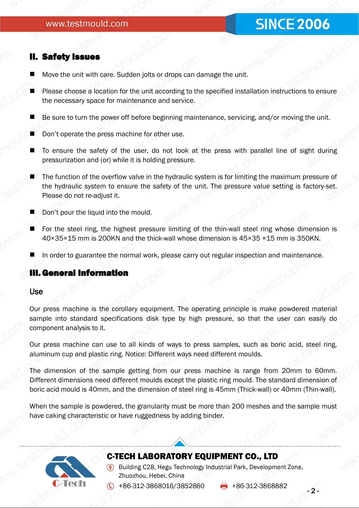
1. Electric cabinet
2. Mains switch
3. Tool tray
4. Adjust bolt
5. Power line
Fig.2 Back of the unit
1. Start button
2. Stop button
3. Lifting button
4. PLC touch screen
5. Exit mould/Falling button
1. Air filter
2. Downward solenoid valve
3. Upward solenoid valve
4. Pressure sensor
5. Low speed solenoid valve
6. Throttle valve
7. Oil level gauge
1
2
3
4
5
2
3
4
5
5
1
3
4
6
7
Fig.3 Operating Panel
Fig.4 Hydraulic unit

- 5 -
Power installation and electrical maintenance should be done by professional.
Before installation,please check the earth resistance. It should be less than 4Ω .
IV. Installation
Preparatory Work before Installation
Before installation, check the machine for damage and loose parts. The unit should be located in
a laboratory or clean industrial environment. The machine should rest on a level and flat surface
so that it will support the unit without shaking.
Install the tool tray with screw on the left of the unit. (3 of Fig.2)
Before use, you must screw off the tank filler cap first and take out the sealing plug and then
screw on the tank filler cap.
Check the oil level (7 of Fig.4); the fluid should be filled just above the middle level of the
indicator. Otherwise fill with YB-N46 anti-wear hydraulic fluid. (1 of Fig.4)
In order to guarantee the reliable work and longer service life of the oil pump, please
i
do not use any other type of hydraulic oil which we don’t permit and ensure the
cleaning and quality of the oil.
Before use, please wipe off the antirust oil on the surface of the unit and mould. But don’t use
cleaning agent with corrosive. In addition, please apply a little grease to the holes and cylindrical
surface of the press head of the mould except the plastic ring mould.
Install power line and set properly the earthed.
Switch on the power when the press tool has not been installed. The PLC starts to finish initial,
then you can see the homepage.
Press down the lifting button or falling button, then the motor starts up. The head of piston rod
should have up or down movement at this time. If not, please power off and adjust the power
phase sequence.
If normal, please press on the lifting button and keep it down, observe the changes of needle of
pressure gage at the same time. The hydro-cylinder piston keeps up going. When the needle of
pressure gage starts uplift, stop pressing the button at once. Now, the piston should have been
- 6 -
up going to the top of the hydro-cylinder. Press on the falling button until the sound of oil pump
starts to change. Redo three times as above to exhaust air in the hydro-cylinder.
Set press tool type, holding pressure and holding time. According to the page prompt, you can
complete the parameter setting.
Adjust the action of adding pressure slowly. Rotate the throttle valve (6 of Fig.4) on the hydraulic
unit properly in a clockwise direction, switch on the swing arm without installing press tool and
press the start button. The piston rod keeps uplifting to the top, but the oil pump is still running.
Now, turn back the throttle valve a little slowly in an anticlockwise direction and observe the
pressure gage at the same time. You will see pressure go up to the needed pressure and then
start to keep pressure and time it. Press on the stop button to finish the program of keeping
pressure. You can do the above action again and again until the speed of adding pressure meets
your need. During the procedure, the friction of hydraulic oil will increase and the oil temperature
will rise quickly. In order to extend the service life of hydraulic oil, the speed of adding pressure
should not be too slowly. Usually, it is suitable that the time adding pressure slowly from starting
to rising to 200KN is 2 to 4 seconds. If adjust the speed of adding pressure slowly, genially, you
should adjust the speed of reducing pressure slowly at the same time.
Press Mould Installation
(1) Boric acid or aluminum cup press tool installation
●The installation steps are as followed:
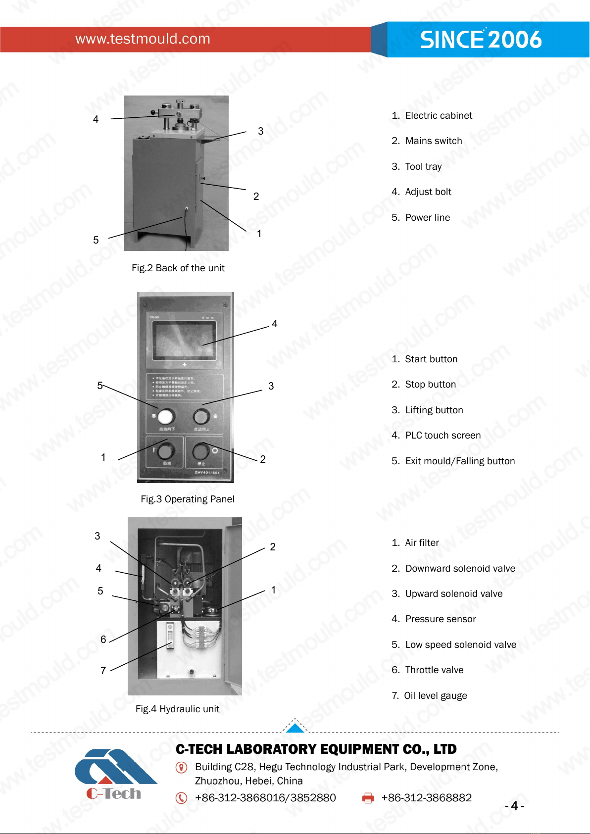
Install the press head. Push away the swinging arm as 4 of fig.1, press on the lifting
button to lift the piston rod to the top. Clear up the sundries on the piston rod and press head.
Put the seating plane of press head into central pit of tool tray(4 of Fig.5) carefully and screw on
the round nut(3 of Fig.5) by special socket spanner(1 of Fig.5). Don’t screw too tight, but must
screw to the end. Cover on pressure spring, but don’t damage the upper plane of press head.
1. Special socket spanner
2. Press head
3. Round nut
4. Central pit of tool tray
5. Nesting
Steel ring
1
2
3
4
5
Fig.5 Press head handling

- 7 -
Install coat. Put the upper cylindrical surface of press head into coat hole and roll the coat in
nesting hole. Press on the falling button to make the coat into nesting completely. Then screw on
the coat in a clockwise direction. When there is positioning feel from hand,it shows the
installation has been finished(Fig.6).
(2) Steel ring press tool installation
●The installation steps are as followed:
Push away the swinging arm as 4 of Fig.1 and screw off the round nut as 3 of Fig.5. Clear up the
sundries on the piston rod (4 of Fig.5) and press head.
Put the press tool coat and press head with press spring into nesting carefully. Don’t damage the
three pieces of dowels around the press tool coat. If the postion is higher, press on the falling
button until the press tool coat down to the properly location.
(3) Plastic ring press tool installation
●The installation steps are as followed:
Install the press head.Push away the swinging arm as 4 of fig.1,press on the lifting button to lift
the piston rod to the top.Clear up the sundries on the piston rod and press head.Put the seating
plane of press head into central pit of tool tray(4 of Fig.5) carefully and screw on the round nut(3
of Fig.5) by special socket spanner(1 of Fig.5). Don’t screw too tight, but must screw to the
end.Cover on pressure spring,but don’t damage the upper plane of press head.
Install the press mould coat. Put the press mould coat into nesting hole.
Install press mould base plate. Put the base plate into nesting hole from top to bottom. Before
installation, clear up the contact surface between base plate and press head. If the postion is
higher, press on the falling button until the press mould coat down to the properly location.
Install top block assembly. Show the screwed hole in central of swinging arm base plate by
screwing the adjust bolt upward. Put the top block assembly into the screwed hole in central of
swinging arm base plate and screw it to the end and then back 1/4 circle. Screw the adjust bolt
tight downward to make the bottom plate of adjust bolt stand up to the top block of press mould.
Running and Adjusting
Press sample with boric acid or aluminum cup
Adjust the adjusting bolt(5 of Fig.1). Push the lifting button to make sure the space between the

- 8 -
undersurface of outer sleeve and top of nesting plate is 0mm. Keep the cover in place, close the
swinging arm and turn adjusting bolt to make the space 1 mm with the cover. Lock the locknut (4
of Fig.2).
Inspect and adjust the setting of pressure and adjust the time of holding pressure.
Adjust the falliing space of press head: Open the swinging arm (4 of Fig.1),Push the start
button.The press head will move up to the top, and then will move down slightly. The press head
will then stop. Put the funnel in the Boric acid tool. Adjust the other parameter on the PLC to
make sure the falling space is 1~2 mm. Refer Fig.7. The adjusting method is as Charpter “About
PLC ”in page 12.
Try to press one sample. The operation step is as flow chart of Fig.8 in page 10.
According to the need, adjust the sample removal time. The default time is 4 seconds.The
method to press sample with aluminum cup is same as with boric acid expect filling sample by
aluminum cup not boric acid.
Fig.7
Fig.6
Press head
Press tool coat
Funnel
- 9 -
Forbid trying to run the program without adding sample into the press mould. Avoid
damage the press mould by confronting the tough with toughness.
Press sample with steel ring
Inspect the status: When switching the swing arm, it shows pressing method is the steel ring.It is
no display when switching on the swing arm.
Inspect and adjust the holding pressure and the holding time.Note: If use thin-wall steel
ring(D40×35×15),the pressure must be set lower than 200KN, and if use thick-wall steel
ring(D40×35×15),the pressure must be set lower than 350KN.
Adjust the position of adjusting bolt:Put the steel ring on the positioning table,fill sample,cover
the press mould coverswitch on the swinging arm and screw the bottom plane of adjusting bolt
to the position which distance from the press cover is 1-2 mm. Screw on the locknut (4 of Fig.2)
tightly.
Try to press one sample. The operation step is as flow chart of Fig.9 in page 11.
Set the falling time of press head. After exit mould, the press mould coat should fall to the
position of positioning step and the press cover should just leave the adjusting bolt in order to
push away the swinging arm easily. If the time of exiting mould is too short, it will be hard to push
away the swinging arm and the springs will push out the press mould. If the time is too long, it
will add the backlash of oil cylinder and the time to press sample. Please set the falling time of
press head to the needed time.
Press sample with plastic ring
Inspect the status: When switching the swing arm, it shows pressing method is the steel ring. It is
no display when switching on the swing arm.
Inspect and adjust the holding pressure and the holding time.
Try to press one sample. The operation step is as flow chart of Fig.9 in page 11.
Set the falling time of press head. After exit mould, the press tool coat should fall to the position
of positioning step. If the time is not properly, please set the falling time of press head to the
needed time.
Elementary Operation
- 10 -
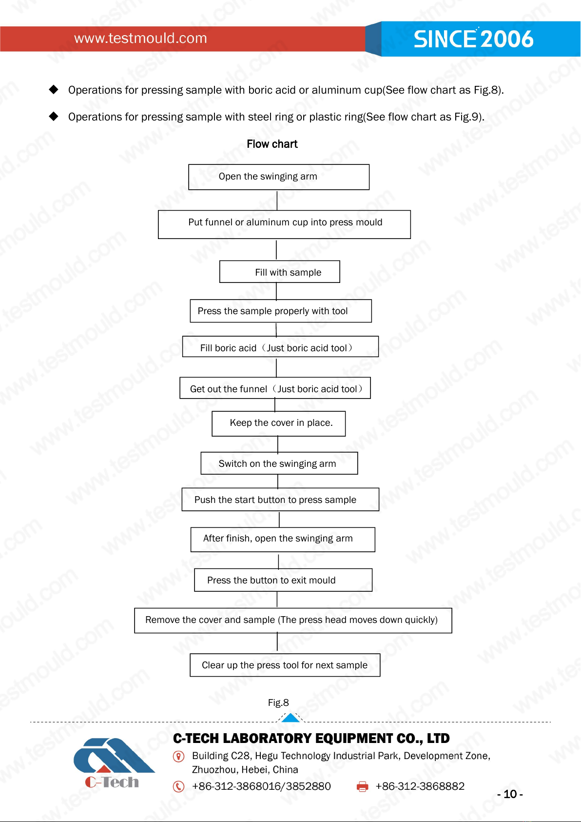
Open the swinging arm
Put funnel or aluminum cup into press mould
Fill with sample
Press the sample properly with tool
Fill boric acid(Just boric acid tool)
Get out the funnel(Just boric acid tool)
Keep the cover in place.
Switch on the swinging arm
Push the start button to press sample
After finish, open the swinging arm
Press the button to exit mould
Remove the cover and sample (The press head moves down quickly)
Clear up the press tool for next sample
Operations for pressing sample with boric acid or aluminum cup(See flow chart as Fig.8).
Operations for pressing sample with steel ring or plastic ring(See flow chart as Fig.9).
Flow chart
Fig.8

- 11 -
Open the swinging arm.
After finish, open the swinging arm.
Switch on the swinging arm.
Flow chart (steel ring) Flow chart (plastic ring)
Fig.9
Before press on the start button, please confirm the press machine has been
ready for the sample press.
During the procedure of sample press, keep your hands away the press mould,
don’t push away the swinging arm and don’t see the mould with eye level.
The spare parts should be handled with care. Specially, the display window of PLC
can’t be incurred by other things.
Put the steel ring.
Fill sample.
Keep the cover in place.
Switch on the swinging arm.
Press the start button to press sample.
Get out the sample.
Clear up the press tool for next sample.
Put plastic ring onthe glaze of tray.
Fill sample.
Put the tray with sample into central
bottom of press mould.
Press the start button to press sample.
After finish, getout the tray.
- 12 -
Clear up the press mould per day. Set down the press head and press coat and
iclean them with carefully. Before next installation, use lubricants to keep them can
move smoothly.
About PLC
There are four buttons and one touch screen on this machine. Start button is used for starting the
program, stop button is used for stopping the program. After pressing the stop button, the motor
will stop and all valves will reset.
The operation of Touch screen is as followed:
Display the homepage as followed when starting.
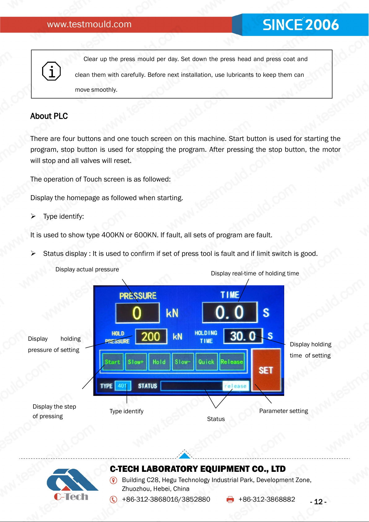
Type identify:
It is used to show type 400KN or 600KN. If fault, all sets of program are fault.
Status display : It is used to confirm if set of press tool is fault and if limit switch is good.
Display actual pressure
Display real-time of holding time
Display holding
pressure of setting
Display holding
time of setting
Display the step
of pressing
Type identify
Status
Parameter setting
- 13 -
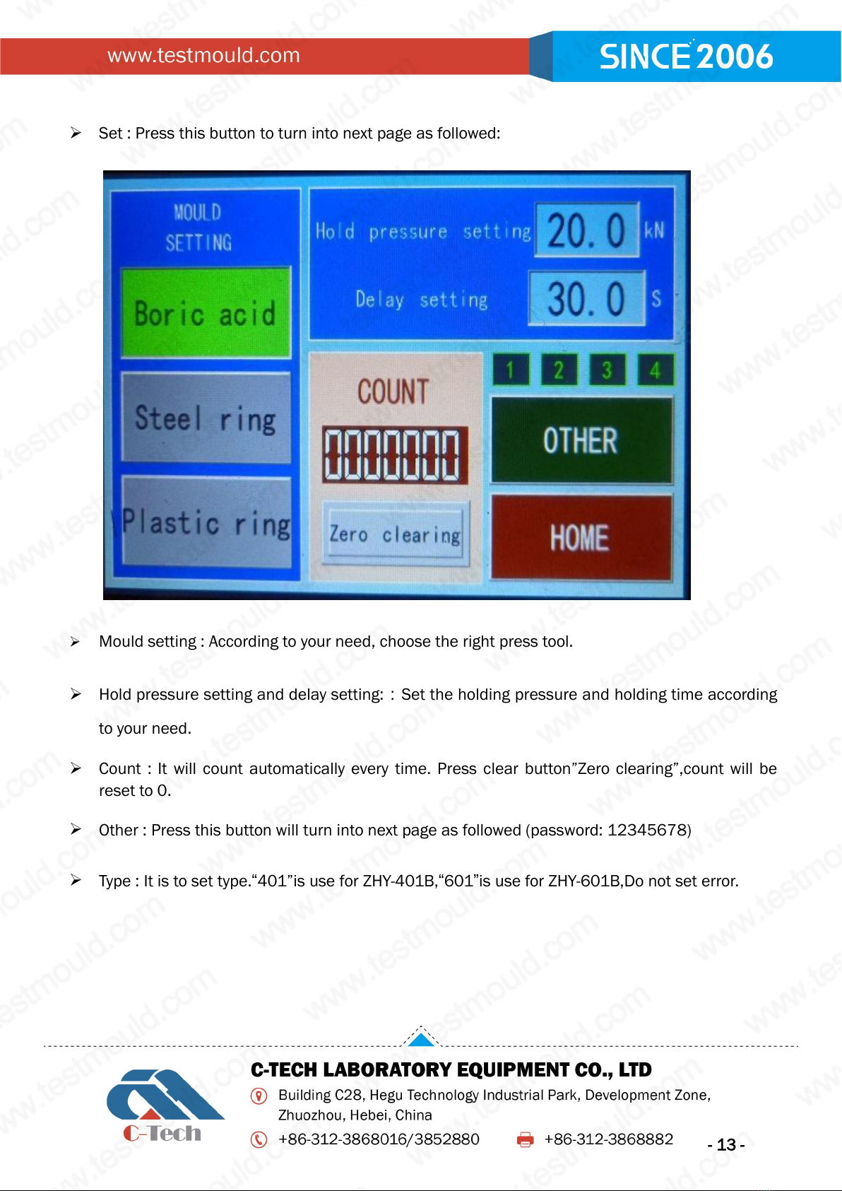
Set : Press this button to turn into next page as followed:
Mould setting : According to your need, choose the right press tool.
Hold pressure setting and delay setting::Set the holding pressure and holding time according
to your need.
Count : It will count automatically every time. Press clear button”Zero clearing”,count will be
reset to 0.
Other : Press this button will turn into next page as followed (password: 12345678)
Type : It is to set type.“401”is use for ZHY-401B,“601”is use for ZHY-601B,Do not set error.

- 14 -
Taking the sample : It is the head holding time for people to take the sample and cover after
refund mould. If its value is too small, people may have no time to take the sample.
Few moving : It is the time of mould drop 1mm automatically after finish boric acid pressing or
aluminum cup pressing.
Demould(boric acid): It is the time for the press head drop to the position next pressing
automatically.
Demould(steel ring): It is the time for the press head drop to the position next pressing
automatically.
Demould(Plastic ring): It is the time for the tray drop to the bottom automatically after finish
plastic ring pressing.
Slow decompression: It is delay time of slow decompression stage after finish the holding
pressure. It will turn into quick decompression stage after this delay time.
Low pressure limit: It is the point when the pressure head from fast-rising to slow pressure.This
value should be set smaller.
Return difference: When holding time is set longer, the pressure may have a little drop. When
pressure difference drops to the limit, the program will do an operation to repair the pressure
automatically.
Pressure correction: If you have more requests for the pressure, you can set the deviation
- 15 -
value. Range:±2.0T.
Note:All parameters will change with type settings. Please do not change type set freely.
Default setting : Press this button, all parameter will reset to default setting. The default setting
is not your need always, so do not press this button freely.
System menu : It is used for setting display time of bright screen.
Home : Pressing this button will be back to homepage.
Indictor light meanings on top right corner:
PWR : Power indictor (Red);It is normally bright.
COM : Communication light(Green);It is quickly flashing.
RUN : PLC running (Indictor Green); It is slowly flashing.
V. Maintenance Instruction
In order to guarantee normal operating of the oil pump,please make the equipment work in
room temperature range 10℃to 40℃.
Our oil tank adopts leak-proof structure to make sure the cleaning of hydraulic oil in oil tank
and avoid polluted hydraulic oil flowing into oil tank.
Under normal circumstances, please check the oil level every 3 months. If leak, find out the
reason, solve with it and check the oil level at once. Supply with the same type of hydraulic oil
to make the oil level is not lower than the middle of oil level indicator.
Change the hydraulic oil in oil tank every 2000 work hours. Before oil change, clean the oil
tank first.
Fill oil in filler hole on the side of swinging arm every 200 work hours. Please use oil gun to fill
with lithium base grease.
Clean the inner and outer wall of the press mould and the compression face at once after use.
Tear down and clean the mould regular, especially to boric acid mould, aluminum cup mould
- 16 -
and steel ring mould. It is best to clean the mould per shift. When cleaning, please take down
the press head and coat from the unit, and clean the mould carefully. Don’t use things with
corrosiveness to clean or sandpaper to polish.Use a little grease to spread on cylindrical
surface of press head and coat hole after cleaning so as to reduce the friction. You can use
dust collector to clean the inner space for installing press head after tearing down the mould.
Take carefully for mould installation to avoid damaging the mould.
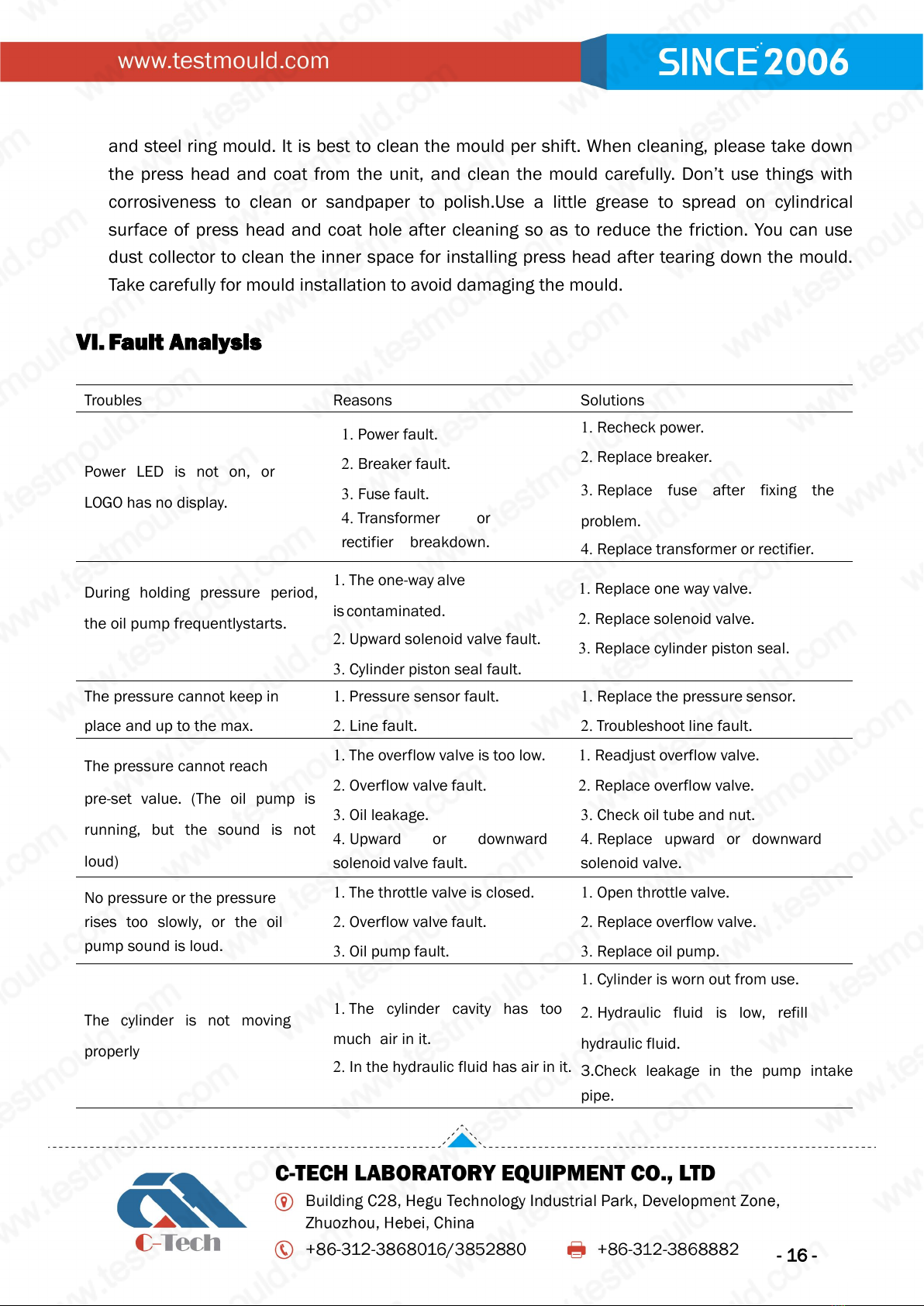
VI. Fault Analysis
Troubles
Reasons
Solutions
Power LED is not on, or
LOGO has no display.
1. Power fault.
2. Breaker fault.
3. Fuse fault.
4. Transformer or
rectifier breakdown.
1. Recheck power.
2. Replace breaker.
3. Replace fuse after fixing the
problem.
4. Replace transformer or rectifier.
During holding pressure period,
the oil pump frequentlystarts.
1. The one-way alve
is contaminated.
2. Upward solenoid valve fault.
3. Cylinder piston seal fault.
1. Replace one way valve.
2. Replace solenoid valve.
3. Replace cylinder piston seal.
The pressure cannot keep in
place and up to the max.
1. Pressure sensor fault.
2. Line fault.
1. Replace the pressure sensor.
2. Troubleshoot line fault.
The pressure cannot reach
pre-set value. (The oil pump is
running, but the sound is not
loud)
1. The overflow valve is too low.
2. Overflow valve fault.
3. Oil leakage.
4. Upward or downward
solenoid valve fault.
1. Readjust overflow valve.
2. Replace overflow valve.
3. Check oil tube and nut.
4. Replace upward or downward
solenoid valve.
No pressure or the pressure
rises too slowly, or the oil
pump sound is loud.
1. The throttle valve is closed.
2. Overflow valve fault.
3. Oil pump fault.
1. Open throttle valve.
2. Replace overflow valve.
3. Replace oil pump.
The cylinder is not moving
properly
1. The cylinder cavity has too
much air in it.
2. In the hydraulic fluid has air in it.
1. Cylinder is worn out from use.
2. Hydraulic fluid is low, refill
hydraulic fluid.
3.Check leakage in the pump intake
pipe.

- 17 -
Troubles
Reasons
Solutions
Without adding pressure
step,stop pump to hold pressure
until the pressure is bigger than
setting pressure.
1. Throttle valve opens too big.
2. Set ON value in B2 is too big.
3. Low speed solenoid valve fault.
1. Readjust throttle valve.
2. Reset LOGO parameters.
3. Replace low speed solenoid
valve.
The breaker is ON and the pump
runs immediately or the pump has
an unusual sound or smell.
SSR fault
Turn breaker OFF and check the power
supply, then replace the SSR, check
oil pump.
There is unusual sound when
exiting mould.
The mould has not been cleaned
for a long time.
Clean the mould per shift and use
grease to spread on cylindrical
surface of press head and coat hole
VII. Main Technical Specifications
Specification
ZHY-401B
ZHY-601B
Maximum pressure
400KN
600KN
Press tool
Boric acid/ Steel ring/Aluminum cup/ Plastic ring
Interval between columns
220mm
Plunger stroke
100mm
Holding-pressure time
0~99 seconds
Power supply
380V±10% 50Hz 3Phase+Earth+Zero
Rated load
1.3kw
Control method
Pressure sensor and PLC
Dimension
615×500×1120mm
655×520×1150mm
Weight
330kg
400kg
Ambient temperature
10-40℃
- 18 -
VIII. About the Warranty Period
The warranty period of the press machine produced by Zhuozhou Tianpeng Instrument
Manufacturing Co.,Ltd. starts from the date of normal operation of the press machine, and lasts for
12months; or starts from date of shipment of the press machine, and lasts for 18 months.
Whichever comes first shall govern.
The warranty does not cover any unit that has been subject to misuse, neglect, negligence, or
accidents.
The warranty does not apply to any failure of the unit that is the result of improper installation or
maintenance, or to any unit that has been operated or maintained in any way contrary to the
operating or maintenance instructions as specified in the user manual. This warranty does not
cover any unit that has been altered or modified so as to change its intended use.
The warranty does not cover any unit that has been lost, caused by force majeure.
Tianpeng reserves the right to change or improve the design of any unit without assuming any
obligation to modify any unit previously manufactured.
Tianpeng assumes no responsibility for incidental, consequential, or other failures including, but
not limited to, loss or fail to property, loss of revenue, loss of use of the unit, loss of time, or
convenience. When replacing the complete press machine and the spare parts, the freight will be
paid for by Tianpeng within the warranty period, and the buyer will pay for the freight beyond the
warranty period.
This manual suits for next models
1
Table of contents
Other C-Tech Industrial Equipment manuals


Popular Industrial Equipment manuals by other brands

Eaton
Eaton CEAG Style 21011 LED CG-S Mounting and operating instructions

SIP
SIP 03692 manual

Watts
Watts FEBCO 880V Series INSTRUCTION, INSTALLATION, MAINTENANCE AND REPAIR MANUAL

matev
matev CLS-SE operating manual

Shaver
Shaver HD-10 Operator's manual

Donaldson Torit
Donaldson Torit RWB-2000 Installation and operation manual


