5
Intended use
Transporting infants and children
with the box closed is not permitted.
When transporting infants and
children, the transport box lid must
not be installed.
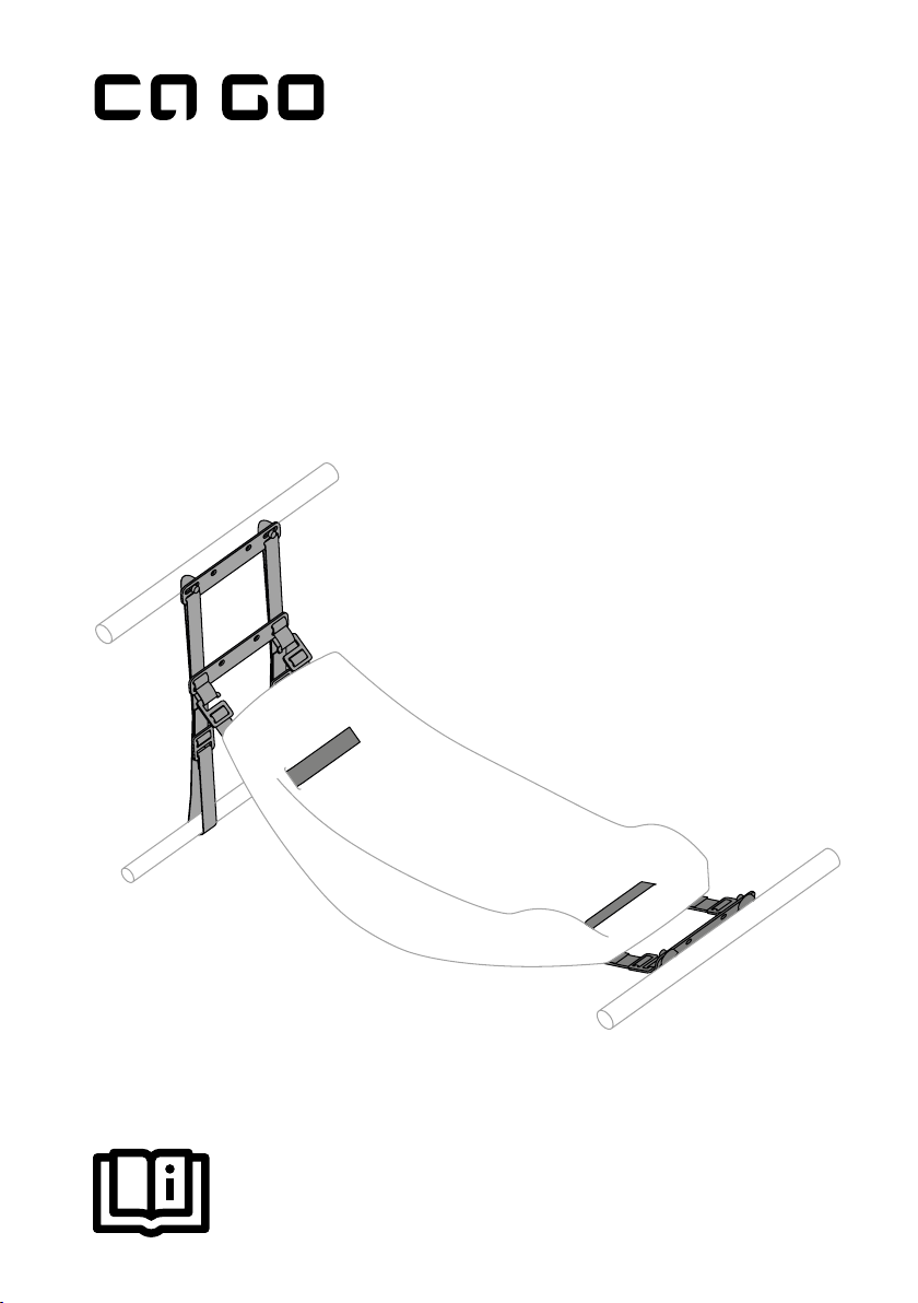
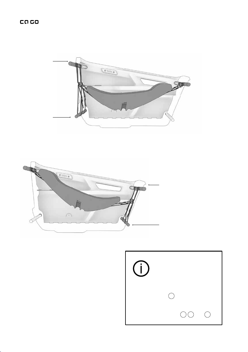
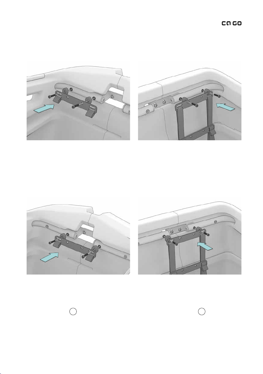
The Infant-Sling-Mount is designed
to install and secure an Infant-Sling
in the FS200 Life. The Infant-Sling-
Mount can be installed centrally in
the transport box or on the left or
right side, according to preference.
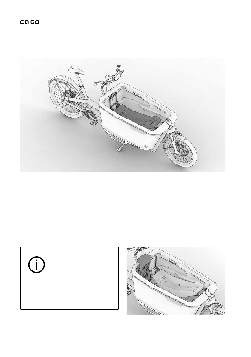
If only an infant is to be transported
in the transport box, we recommend
installing the Infant-Sling-Mount in
the central position.
The Infant-Sling-Mount can be hung
into the transport box either in the
direction of travel or against it.
We recommend installation against
the direction of travel, since this will
allow the structure to better absorb
any inertia forces.
Every child and every infant must
be transported in a child seat or
Infant-Sling that is suitable for his or
her speciic height and weight. They
must be strapped in at all times.
The FS200 Life is designed for the
transport of up to two children, or
one child and one infant.
The Infant-Sling-Mount is designed
for infants aged 0 to 9months
and weighing up to 9kg. Beyond
this speciication, the operating
instructions and speciications of the
respective Infant-Sling-Mount must
be observed. It is important to check
and ensure that the Infant-Sling-
Mount is suitable for the intended
fastening system and can be tied
down safely.