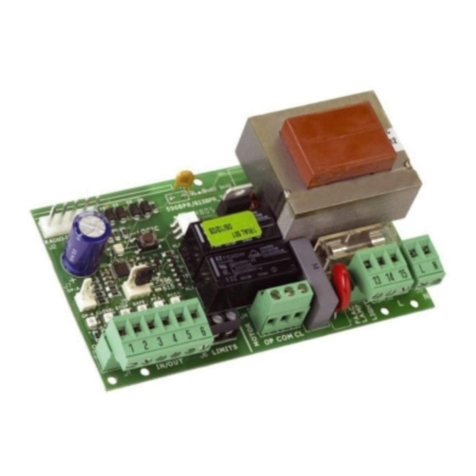
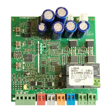
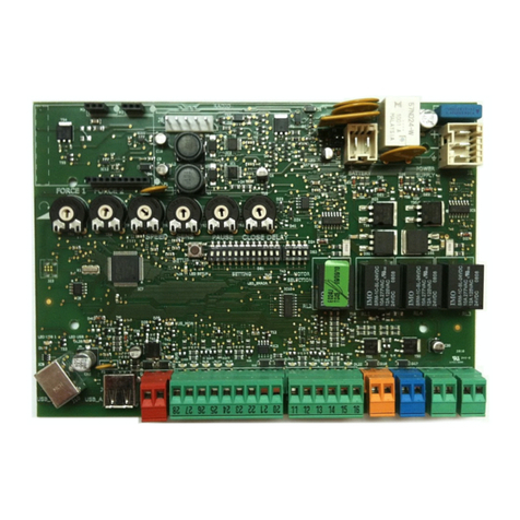
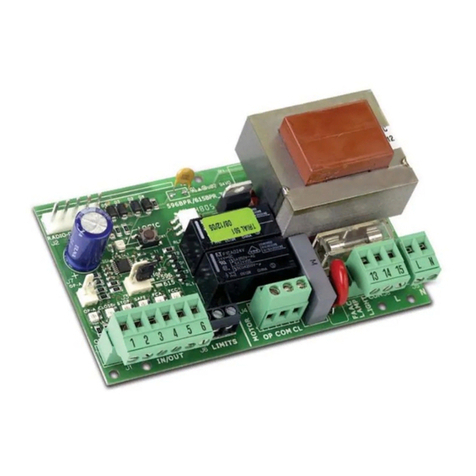
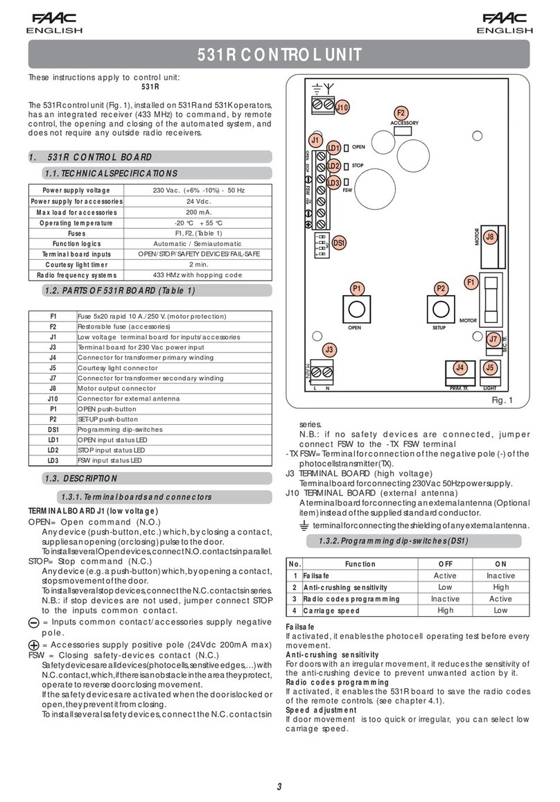
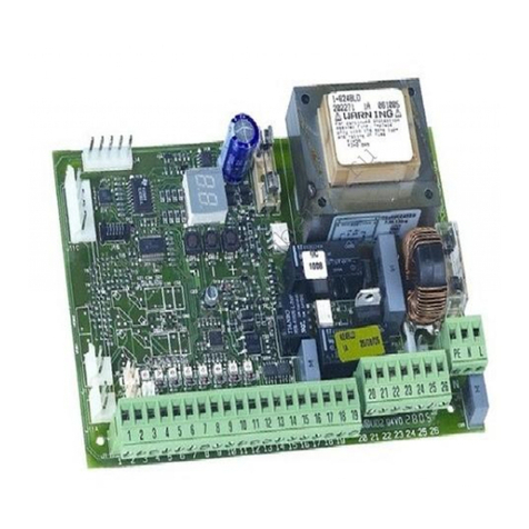
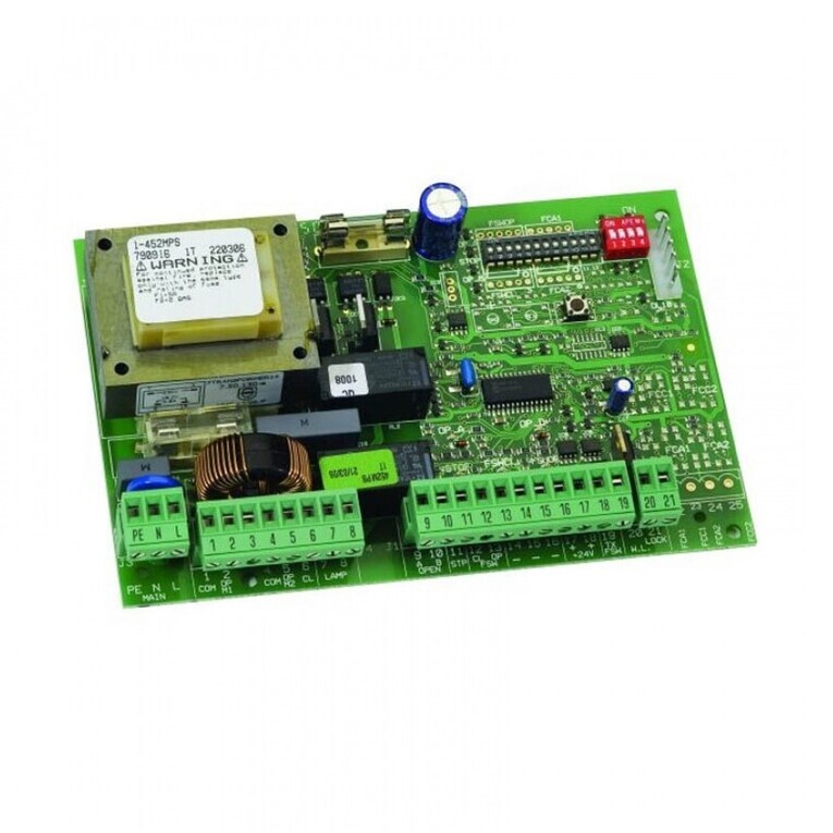
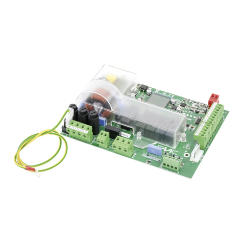
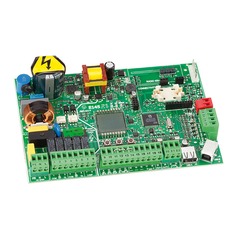
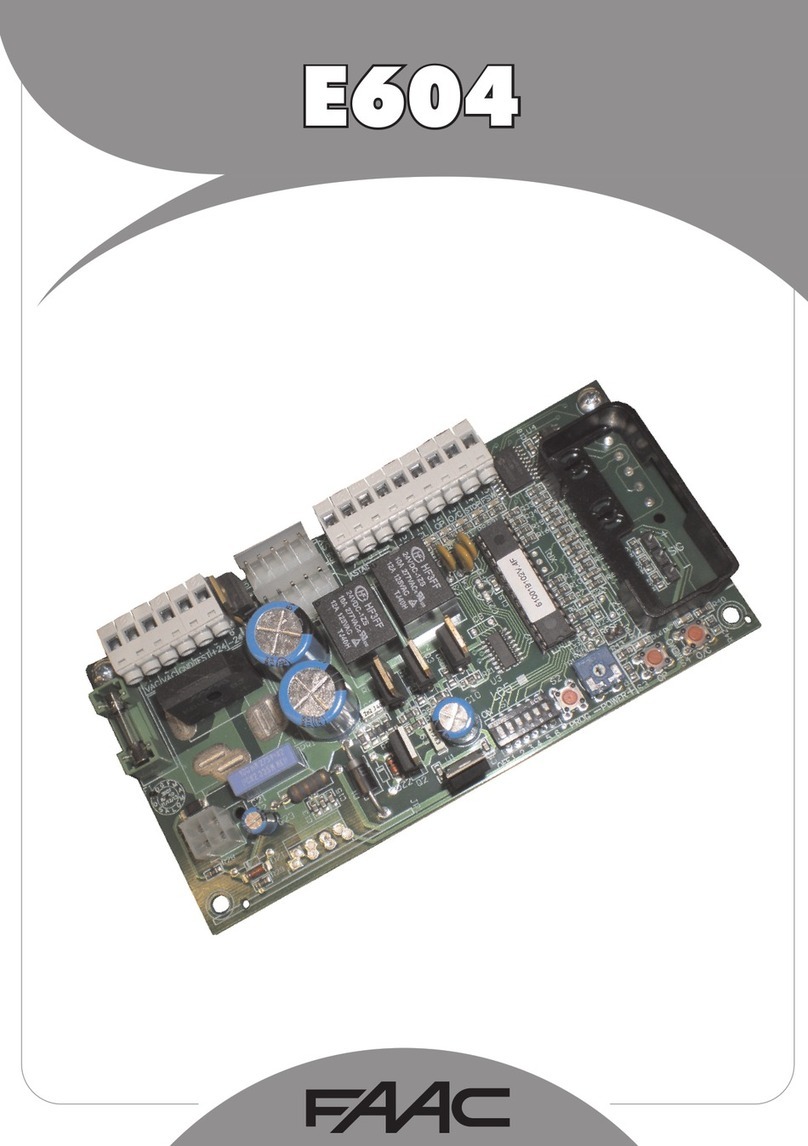
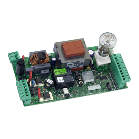
FAAC E1SL User manual

E1SL
SDK EVO
LK EVO
KS EVO
E1SL FW 3.4
SDK EVO FW 3.4
LK EVO FW 1.3
KS EVO FW 1.0
This document contains updated instructions starting from the FW versions indicated:
EN

FAAC S.p.A. Soc. Unipersonale
Via Calari, 10 - 40069 Zola Predosa BOLOGNA - ITALY
Tel. +39 051 61724 - Fax +39 051 09 57 820
www.faac.it - www.faacgroup.com
© Copyright FAAC S.p.A. dal 2018.Tutti i diritti riservati.
Nessuna parte di questo manuale può essere riprodotta, archiviata, distribuita a terzi
né altrimenti copiata, in qualsiasi formato e con qualsiasi mezzo, sia esso elettronico,
meccanico o tramite fotocopia, senza il preventivo consenso scritto di FAAC S.p.A.
Tutti i nomi e i marchi citati sono di proprietà dei rispettivi fabbricanti.
I clienti possono effettuare copie per esclusivo utilizzo proprio.
Questo manuale è stato pubblicato nel 2018.
© Copyright FAAC S.p.A. from 2018. All rights reserved.
No part of this manual may be reproduced, archived, distributed to third parties nor
copiedin anyother way, in anyformatand withany means,be itelectronic, mechanical
or by photocopying, without prior written authorisation by FAAC S.p.A.
All names and trademarks mentioned are the property of their respective manu-
facturers.
Customers may make copies exclusively for their own use.
This manual was published in 2018.
© Copyright FAAC S.p.A. depuis 2018.Tous droits réservés.
Aucune partie de ce manuel ne peut être reproduite, archivée ou distribuée à des tiers
ni copiée, sous tout format et avec tout moyen, qu’il soit électronique, mécanique ou
par photocopie, sans le consentement écrit préalable de FAAC S.p.A.
Tous les noms et les marques cités sont la propriété de leurs fabricants respectifs.
Les clients peuvent faire des copies pour leur usage exclusif.
Ce manuel a été publié en 2018.
© Copyright FAAC S.p.A. ab dem 2018. Alle Rechte vorbehalten.
Kein Teil dieses Handbuchs darf reproduziert, gespeichert, an Dritte weitergegeben
oder sonst auf eine beliebige Art in einem beliebigen Format und mit beliebigen
Mitteln kopiert werden, weder mit elektronischen, noch mechanischen oder durch
Fotokopieren, ohne die Genehmigung von FAAC S.p.A.
Alle erwähnten Namen und Marken sind Eigentum der jeweiligen Hersteller.
Die Kunden dürfen nur für den Eigengebrauch Kopien anfertigen.
Dieses Handbuch wurde 2018 veröffentlicht.
© Copyright FAAC S.p.A. del 2018.Todos los derechos están reservados.
Nopuede reproducirse,archivarse,distribuirse atercerosni copiarse de ningún modo,
ninguna parte de este manual, con medios mecánicos o mediante fotocopia, sin el
permiso previo por escrito de FAAC S.p.A.
Todos los nombrey las marcascitadas sonde propiedad de los respectivosfabricantes.
Los clientes pueden realizar copias para su uso exclusivo.
Este manual se ha publicado en 2018.
© Copyright FAAC S.p.A. van 2018. Alle rechten voorbehouden.
Niets uit deze handleiding mag gereproduceerd, gearchiveerd, aan derden openbaar
gemaakt of op andere wijze gekopieerd worden, in om het even welke vorm en
met geen enkel middel, noch elektronisch, mechanisch of via fotokopiëren, zonder
schrfitelijke toestemming vooraf van FAAC S.p.A.
Alle vermelde namen en merken zijn eigendom van de respectievelijke fabrikanten.
De klanten mogen kopieën maken die enkel voor eigen gebruik bestemd zijn.
Dez handleiding werd in 2018 gepubliceerd.

E1SL 3 53225804 - Rev. B
Translation of the original instructions ENGLISH
TABLES
1 Assigning the Operating mode ...................................... 8
2 Configurable inputs ...............................................10
3 Configurable inputs programming..................................10
4 Configurable outputs ..............................................12
5 Programming Configurable Outputs ................................ 12
6 BASIC Programming............................................... 16
7 ADVANCED programming ..........................................18
8 Pre-set ID associations.............................................29
9 Upload/Download Menu........................................... 33
10 Status of the automation ..........................................35
11 Errors and Warnings ............................................... 36
12 Troubleshooting guide.............................................39
13 LED Error Coding on Function selectors ..............................41
14 LED Warning coding - LK EVO....................................... 41
15 FW version LED coding - LK EVO .................................... 41
16 FUNCTIONS menu ........................................... 46
CONTENTS
1. ELECTRONIC MODULE E1SL ............................................. 4
Board E1SL ........................................................... 4
Status LEDs on the board.............................................. 5
Terminal boards and connectors ....................................... 5
2. DM BOARD.............................................................. 6
Installing the DM board ............................................... 6
Connecting the second motor ......................................... 6
Enabling the DM KIT .................................................. 6
3. OPERATING MODE MODFUN........................................... 8
4. CONNECTIONS .......................................................... 9
5. CONFIGURABLE INPUTS................................................ 10
PROGRAMMING ..................................................... 10
Connections......................................................... 10
Automatic Opening Inputs ........................................... 11
SEMI-AUTOMATIC OPEN input......................................... 11
Safety inputs........................................................ 11
Operating mode inputs .............................................. 11
TIMER input ......................................................... 11
RESET input ......................................................... 11
6. CONFIGURABLE OUTPUTS.............................................. 12
PROGRAMMING ..................................................... 12
Connections......................................................... 12
7. STARTUP.............................................................. 13
Set-up procedure .................................................... 13
7.1 Turn the power on .................................................... 13
7.2 SETUP ............................................................... 14
7.3 Restoring factory settings ............................................. 14
7.4 Programming the board .............................................. 15
7.5 Movement parameters................................................ 20
7.6 Obstacle detection.................................................... 20
7.7 Low Energy .......................................................... 20
7.8 Intrusion............................................................. 20
KEEP CLOSED ........................................................ 20
PULL & GO........................................................... 20
7.9 Energy Saving ....................................................... 20
7.10 Timing and partial opening .......................................... 20
7.11 Date and Time....................................................... 21
7.12 Cycle counter - Scheduled maintenance ............................... 21
7.13 TIMER .............................................................. 22
WEEKLY PROGRAMMING ............................................. 22
JOLLY PROGRAMMING................................................ 22
ENABLING/DISABLING THE TIMER ..................................... 22
8. ACCESSORIES .......................................................... 23
Emergency battery .................................................. 23
XB LOCK motor block and monitoring (optional) ....................... 23
XM LOCK motor block and monitoring................................. 24
ELASTIC Kit.......................................................... 24
One Dual Technology entry and exit detector .......................... 25
2 Dual Technology entry and exit detectors............................ 26
Infrared detector for safety in opening ................................ 27
XFA button photocells................................................ 28
9. INTERCOM ............................................................. 29
Installing INTERCOM ................................................. 29
Assigning an ID...................................................... 29
Operation ........................................................... 29
Temporarily disabling a board ........................................ 29
INTERCOM diagnostics ............................................... 29
9.1 INTERLOCK ........................................................... 30
Installing INTERLOCK................................................. 30
Enabling / disabling INTERLOCK....................................... 30
9.2 AIRSLIDE............................................................. 31
Installing AIRSLIDE .................................................. 31
9.3 INTERLEAVES......................................................... 32
Installing INTERLEAVES .............................................. 32
10. FW UPDATES AND FILE DOWNLOAD USB............................. 33
AutoUpdate ......................................................... 33
Upload/Download Menu ............................................. 33
Bootloader and FW versions.......................................... 33
11. DIAGNOSTICS......................................................... 34
LEDs on the board ................................................... 34
Automation and configured inputs status ............................. 35
Errors and Warnings ................................................. 35
FW versions ......................................................... 35
11.1 Reset............................................................... 38
12. LK EVO................................................................ 40
LK EVO lock device ................................................... 41
13. KS EVO................................................................ 42
14. SDK EVO .............................................................. 43
SDK EVO lock device.................................................. 43
Home page.......................................................... 44
Reset - Lock/Release................................................. 44
PASSWORD (PSW) ................................................... 44
MODFUN ............................................................ 45
MENU ........................................................... 45
PROGRAMMING ..................................................... 45
Menu 1 language.................................................... 48
Menu 2 Programming................................................ 48
Menu 3 ERRORS ..................................................... 49
Menu 4 INDICATIONS................................................. 49
Menu 5 CYCLE COUNTER.............................................. 49
Menu 6 DATE / TIME.................................................. 49
Menu 7 TIMER ....................................................... 49
Menu 8 PASSWORD .................................................. 50
Menu 9 INFO ........................................................ 50

1
2
E1SL 4 53225804 - Rev. B
0.0
RESET/SETUP
DL2 DL11
MAIN
F1
USB
+
-
F
ERR
BAT1
OPEN
EMERG
BAT2
SIC_OP
SIC_CL
J10
J14
J11
J12 J13
V G
S1
G
T
J
1
J17
V RX TX G
J8
E1 G E2
J7
T1 G
T2
R1
G R2
J9
V G 01 02 02
J22
J21
V
G
I1
I2
G
I3
I4
V
J18
G CH CL G
J23J24
J25
V G
S2
G
T
J4
0.0
RESET/SETUP
DL2 DL11
MAIN
F1
USB
+
-
F
ERR
BAT1
OPEN
EMERG
BAT2
SIC_OP
SIC_CL
J10
J14
J11
J12 J13
V G
S1
G
T
J
1
J17
V RX TX G
J8
E1 G E2
J7
T1 G
T2
R1
G R2
J9
V G 01 02 02
J22
J21
V
G
I1
I2
G
I3
I4
V
J18
G CH CL G
J23J24
J25
V G
S2
G
T
J4
SW1
SETUP RESET
SW3
+
SW4
F
SW2
-
F1 F2
Translation of the original instructions ENGLISH
POWER SUPPLY UNIT
ELECTRONIC BOARD E1SL
1. ELECTRONIC MODULE E1SL
Display Clock battery: lithium 3V CR2032
(NOT SUPPLIED)
Switching power supply 230V~ +6% -10%
self-protected from overloads
Mains power supply input
(230V~ +6% -10%)
F3
(removable support)
Fuses
F1 battery protection 8 A T (delayed)
F2 accessory protection 2 A F (quick)
F3 power supply unit primary protection 2.5 A T (delayed) 5x20 mm
BOARD E1SL
! DO NOT remove this cover
Buttons
SW1 SETUP / RESET
SW2 -”(scrolls programming values)
SW3 “+”(scrolls programming values)
SW4 “F”(programming: scrolls functions/confirms values)
The E1SL electronic module is designed to control FAAC automation
models A1000, A1400 AIR, RKE 1400, SF1400, GBF1500. The instal-
lation instructions must be followed.
Motorised pedestrian doors fall within the scope of the type “C”
harmonised European Standard EN 16005:2012. It is assumed that
automation systems manufactured in accordance with this standard
also comply with the essential safety requirements of the Directive
2006/42/EC.
This however does not exempt the manufacturer from carrying out
a risk analysis in order to implement appropriate measures for those
risks that are not covered by the standard or by the manufacturers of
the components. FAAC S.p.A. recommends that you always comply
with the EN 16005:2012 standard and in particular that you adopt the
criteria and safety devices indicated, without exception.

3
4
E1SL 5 53225804 - Rev. B
0.0
RESET/SETUP
DL2 DL11
MAIN
F1
USB
+
-
F
ERR
BAT1
OPEN
EMERG
BAT2
SIC_OP
SIC_CL
J10
J14
J11
J12 J13
V G
S1
G
T
J
1
J17
V RX TX G
J8
E1 G E2
J7
T1 G
T2
R1
G R2
J9
V G 01 02 02
J22
J21
V
G
I1
I2
G
I3
I4
V
J18
G CH CL G
J23J24
J25
V G
S2
G
T
J4
J24
J25
J22 J18
J7
J4
J1
J9
J23
J17
J13
J12
J11
J14
J10
J21
J8
0.0
RESET/SETUP
DL2 DL11
MAIN
F1
USB
+
-
F
ERR
BAT1
OPEN
EMERG
BAT2
SIC_OP
SIC_CL
J10
J14
J11
J12 J13
V G
S1
G
T
J
1
J17
V RX TX G
J8
E1 G E2
J7
T1 G
T2
R1
G R2
J9
V G 01 02 02
J22
J21
V
G
I1
I2
G
I3
I4
V
J18
G CH CL G
J23J24
J25
V G
S2
G
T
J4
USB
BAT2
SIC_CL
OPEN
SIC_OP
EMERG
DL2
BAT1
MAIN
ERR
DL11
Translation of the original instructions ENGLISH
LED Description
MAIN BLUE main power supply unit input
DL2 BLUE board power +5V
DL11 BLUE accessories power (+24V ")
USB GREEN USB storage device
ERR RED error or warning
BAT1 RED battery status
BAT2 GREEN battery charger status
SIC_OP RED safety in opening SIC_OP and SIC_CL lit simultaneously = safety STOP
SIC_CL RED safety in closing
EMERG GREEN emergency command
OPEN GREEN OPEN command
STATUS LEDS ON THE BOARD
J1 Removable terminal board configurable inputs S1
J4 Removable terminal board configurable inputs S2
J7 Removable terminal board configurable inputs E1, E2
J8 Removable terminal board keypad or EVO functions selector
J9 Removable terminal board for button photocells
J10 Connector for main power supply 36V, 4 A
J11 Connector for motor M1
J12 Connector for motor M1 encoder
J13 Connector for motor block and monitoring
J14 Connector for emergency battery
J17 USB port
J18 Removable terminal board INTERCOM
J21 Removable terminal board configurable inputs I1, I2, I3, I4
J22 Removable terminal board configurable outputs O1, O2
J23
J24
J25
Connectors for optional modules NOT USED
TERMINAL BOARDS AND CONNECTORS

5
E1SL 6 53225804 - Rev. B
0.0
RESET/SETUP
DL2 DL11
MAIN
F1
USB
+
-
F
ERR
BAT1
OPEN
EMERG
BAT2
SIC_OP
SIC_CL
J10
J14
J11
J12 J13
V G
S1
G
T
J
1
J17
V RX TX G
J8
E1 G E2
J7
T1 G
T2
R1
G R2
J9
V G 01 02 02
J22
J21
V
G
I1
I2
G
I3
I4
V
J18
G CH CL G
J23J24
J25
V G
S2
G
T
J4
1
2
3
4
5
4
Translation of the original instructions ENGLISH
A DM board must be installed on automations fitted with a double
motor.
INSTALLING THE DM BOARD
! Before proceeding, disconnect the mains power supply and disconnect
the emergency battery (if present).
1. Remove the E1SL board: remove all the connections, the screw
(1) and the screw with washer (2), then remove the board from
the support (3).
2. Unscrew the 2 screws (4) and remove the plastic cap, pulling out
the 2 pins (5).
3. Install theDM board Refer to 6, install the 4 posts (6) on the E1SL
board and fasten them using the screws provided (7). Insert the
2 comb connectors into the connectors of the E1SL board as far as
the connector (8). Insert the DM board (9) on the side opposite
the comb connectors, as far as the connector (8). Fasten the DM
board onto the 4 posts using the screws provided (10).
4. Replace the plastic cap, inserting the 2 pins (5) into the board
E1SL. Fasten it using the 2 screws (4).
5. With reference to 5, Reinstall the E1SL board into the seats
(3). Fix in position with the screw (1) and the screw with washer
(2). IMPORTANT: the washer provides the board's earth connection.
6. Restore all connections.
CONNECTING THE SECOND MOTOR
1. Extend the motor cable using the cable with connector and the
terminal connector provided.
2. With reference to 7, insert the connector (11) onto the board
DM (12). Follow the colour coding of the wires.
ENABLING THE DM KIT
During programming:
- from Board, advanced programming: dM = Y
or
- from SDK EVO:
/PROGRAMMING/INSTALLATION/2ND ENGINE KIT = ENABLED
Removing/reinstalling the E1SL board
Removing/reinstalling the cap
2. DM BOARD

6
7
E1SL 7 53225804 - Rev. B
6
8
7
10
9
12
11
!
Translation of the original instructions ENGLISH
red
black
Installing the DM board
2nd MOTOR connection

E1SL 8 53225804 - Rev. B
Translation of the original instructions ENGLISH
3. OPERATING MODE MODFUN
The operating mode of the automation can be assigned using the
devices shown in the table on this page and from theTIMER (relative
§ Section). Note: the order of priority for assigning the mode is: TIM-
ER, Configured input, Function selector (KS EVO, LK EVO, SDK EVO).
■AUTOMATIC mode
The automation CLOSES AUTOMATICALLY after the programmed
pause time.
TWO-DIRECTIONAL Two-directional transit is allowed (Internal Opening
and External Opening enabled).
EXIT ONLY Only exiting is allowed (External open disabled).
ENTRY ONLY Only entry is allowed (Internal Open disabled).
■AUTO MANUAL mode
The automation allows MANUAL OPENING and CLOSES AUTOMATI-
CALLY after the set pause time.
■MANUAL mode
The leaves are free to move and may only be manually operated. No
command is active.
Before exiting from this mode, make sure that the leaves can be
moved safely. When you exit from MANUAL mode, the board will
carry out a RESET.
■OPEN mode
The automation opens and remains open.
■NIGHT-TIME mode
The automation closes and remains closed. External Opening is
disabled. Internal Opening is enabled only in the time interval pro-
grammed as NIGHT-TIME MODE DELAY. It can only be opened via
Key, Emergency Opening and Pharmacy open inputs (with automatic
closing after the NIGHT PAUSE time).
■INTERLOCK mode
The opening of one automation is subject to the closing of another (§
specific Section). INTERLOCK can be selected forTWO-DIRECTIONAL
transit, ENTRY ONLY, or EXIT ONLY.
1 Assigning the Operating mode
Function
(
*
) = NOT available for SF1400 and GBF1500 SDK EVO LK EVO/KS EVO Programming the configurable input
AUTOMATIC TWO-DIRECTIONAL
TOTAL
100%
-
PARTIAL (
*
)
%45
AUTOMATIC EXIT ONLY
TOTAL
100%
41
PARTIAL (
*
)
%--
AUTOMATIC ENTRY ONLY
TOTAL
100% -42
PARTIAL (
*
)
%--
AUTO MANUAL
TOTAL
100% -47
PARTIAL (
*
)
%--
MANUAL 44
OPEN
TOTAL 100%
40
PARTIAL (
*
)%--
NIGHT
TOTAL 100% 43
PARTIAL (
*
)%--
INTERLOCK TWO-DIRECTIONAL
TOTAL
100% -46
PARTIAL (
*
)
%--
INTERLOCK EXIT ONLY
TOTAL
100% --
PARTIAL (
*
)
%--
INTERLOCK ENTRY ONLY
TOTAL
100% --
PARTIAL (
*
)
%--

8
E1SL 9 53225804 - Rev. B
MAIN
F1
J
10
J
14
J11
J12
J12
J11
Translation of the original instructions ENGLISH
4. CONNECTIONS
RISKS
PERSONAL PROTECTIVE EQUIPMENT
REQUIRED TOOLS
F Before working on the board, always turn off the mains power supply
and disconnect the emergency battery (if present). Turn the power
back on only after completing all the electrical connections and carrying
out the preliminary start-up checks.
The maximum total load of accessories connected to the board (+24V
") must not exceed 1A (except SDK EVO).
1. The motor M1 must be connected to connector J11.
2. The encoder must be connected to connector J12.
3. A DM board must be installed on automations fitted with a double
motor in compliance with the instructions provided in the specific
chapter.
4. For connecting additional devices, where present, please refer to
the specific chapters:
-XB LOCK or XM LOCK motor block
-XFA button photocells
-XV1 or XDT1 detectors, single or double, exit and entry, for open-
ing and safety in closing
-XBFA ON detectors for safety in opening
-Configurable inputs
-Configurable outputs
-LK EVO, KS EVO, SDK EVO function selectors
Motor M1 and encoder connection

E1SL 10 53225804 - Rev. B
0
DL11
USB
F
ERR
BAT1
OPEN
EMERG
BAT2
SIC_OP
SIC_CL
J13
V G
S1
G
T
J
1
V RX TX G
J8
E1 G E2
J7
T1 G
T2
R1
G R2
J9
V G 01 02 02
J22
J21
V
G
I1
I2
G
I3
I4
V
J18
G CH CL G
J23J24
J25
V G
S2
G
T
J4
J21
J4
J7
J1
Translation of the original instructions ENGLISH
5. CONFIGURABLE INPUTS
2 Configurable inputs
Input
(terminalboard)
Default Programming Board function:
(default)
I1
(J21)
External OPENING (NO) C1 (1)
I2 Internal OPENING (NO) C2 (4)
I3 KEY (NO) C3 (10)
I4 Automatic Opening (NO) C4 (7)
S1 (J1) Closing Safety (NC)
TEST enabled
P1 (20)
1F (Y)
S2 (J4) Closing Safety (NC)
TEST enabled
P2 (20)
2F (Y)
E1 (J7) not enabled E1 (no)
E2 not enabled E2 (no)
3 Configurable inputs programming
from SDK EVO from Board
input NOT enabled no
EXTERNAL OPENING 1(NO)
INTERNAL OPENING 4(NO)
AUTOMATIC OPENING 7(NO)
SEMI-AUTOMATIC OPENING 8(NO)
PHARMACY OPEN (NOT for SF1400 and GBF1500) 9(NO)
KEY 10(NO)
PARTIAL OPEN (NOT for SF1400 and GBF1500) 11 (NO)
CLOSING SAFETY (TEST available) 20 (NC)
OPENING SAFETY (TEST available) 21 (NC)
SAFETY STOP (TEST available) 23 (NC)
EMERGENCY OPENING 30 (NC)
EMERGENCY OPENING with MEMORY 31 (NC)
EMERGENCY STOP 32 (NC)
EMERGENCY STOP with MEMORY 33 (NC)
EMERGENCY CLOSING 34 (NC)
EMERGENCY CLOSING with MEMORY 35 (NC)
EMERGENCY BREAK OUT 37 (NC)
TOTALLY OPEN 40 (NO)
AUTOMATIC EXIT ONLY TOTAL 41 (NO)
AUTOMATIC ENTRY ONLY TOTAL 42 (NO)
NIGHT TOTAL 43 (NO)
MANUAL 44 (NO)
AUTOMATIC TWO-DIRECTIONAL PARTIAL (NOT for SF1400 and
GBF1500) 45 (NO)
INTERLOCK TWO-DIRECTIONAL TOTAL 46 (NO)
AUTO MANUAL TOTAL 47 (NO)
TIMER 60 (NO)
RESET 61 (NO)
These inputs have an assigned function (Configurable inputs),
which are modifiable in programming. Some functions vary if the
Energy Saving is active (relative § Section).
PROGRAMMING
For the available options, see Programming configurable Inputs
and the following sections. The input is activated according to how
the contact logic is programmed: NO = the input activates when the
contact closes, NC = the input activates when the contact opens.
- fromBoard: Basic Programmingfor theinputs of terminalboard J21. Advanced
Programming for the inputs of terminal boards J1, J4 and J7.
The default contact logic can only be modified via the SDK EVO. The test (1F, 2F...)
is only available for the inputs configured as Opening Safety, Closing Safety and
Safety STOP.
-from SDK EVO:
/PROGRAMMING/INPUTS/OUTPUTS …
…
INPUTS I1-I4 or INPUTS S1-S2 or INPUTS E1/E2 (select the input)
…
FUNCTION (select no…61)
…
NO/NC (the contact logic must be programmed according to the type of contact
of the device)
…
TEST (available for inputs configured as Safeties)
CONNECTIONS
Only connect devices with a volt free contact to configurable in-
puts. The contact of the device must be connected between the
input and GND.
I1, I2, I3, I4 (TERMINAL BOARD J21)
V
G
I1
I2
G
I3
I4
V
V+24 V "accessories power supply
I4 Configurable input I4
I3 Configurable input I3
G GND Accessories power supply negative and Common contacts
I2 Configurable input I2
I1 Configurable input I1
G GND Accessories power supply negative and Common contacts
V+24 V "accessories power supply
S1 (TERMINAL BOARD J1), S2 (TERMINAL BOARD J4)
V G
S1
G
T
V G
S2
G
T
TTEST
GGND Power supply negative and Common contacts
S1 Configurable input S1
GGND Power supply negative and Common contacts
V+24 V "(accessories power supply)
TTEST
GGND Power supply negative and Common contacts
S2 Configurable input S2
GGND Power supply negative and Common contacts
V+24 V "(accessories power supply)
E1, E2 (TERMINAL BOARD J7)
E1 G E2
E2 Configurable input E2
GGND Accessories power supply negative and Common contacts
E1 Configurable input E1

E1SL 11 53225804 - Rev. B
Translation of the original instructions ENGLISH
AUTOMATIC OPENING INPUTS
When one of the following inputs is activated, the automation opens
and closes again after the pause time. The automation does not close
as long as the input is active.
EXTERNAL OPENING (1) Input specifically for external control devic-
es. The input is disabled in NIGHT-TIME or EXIT ONLY mode.
INTERNALOPENING (4) Input specifically for internal control devices. The
input is disabled in ENTRY ONLY mode. In NIGHT-TIME mode, the
input is enabled only in the time interval programmed as NIGHT-TIME
MODE DELAY.
AUTOMATIC OPENING (7) The input is disabled in NIGHT-TIME mode (it is
enabled in EXIT ONLY and ENTRY ONLY mode).
PHARMACY OPEN (9) In NIGHT mode, the command opens the leaves
to the percentage programmed in PARTIAL PHARMACY. The input
opens the leaves automatically in the other operating modes.
KEY (10) Command also enabled in NIGHT-TIME mode.
PARTIAL OPEN (11) Partially opens the automation to the programmed
percentage. It is NOT enabled in the NIGHT mode.
SEMIAUTOMATIC OPEN INPUT
(8) When the input is activated with the automation closed, the au-
tomation opens (TOTAL or PARTIAL according to the operating mode
selected) and remains open. When the input is activated with the
automation open, it closes it.
The input is NOT active in NIGHT-TIME mode.
SAFETY INPUTS
! Use monitored safety devices that are compliant with standard
EN 16005:2012 on inputs configured for safety functions.
On the inputs configured as Safeties, the Test to make sure that the
automation works correctly must be enabled before movement
takes place. If the test isn’t passed, movement is inhibited (TEST
ERROR). Alternatively, from SDK EVO it is possible to enable move-
ment in Low Energy mode.
/PROGRAMMING/MISCELLANEUS/TEST ERROR ENABLED = movement inhib-
ited, DISABLED = movement in Low Energy mode.
CLOSING SAFETY (20) Connect the closing safety devices. When this
input is activated:
- during closing, the automation reverses the movement
- when the automation is open, it prevents it from closing
- when the automation is paused, it resets the pause time
OPENING SAFETY (21) Connect the opening safety devices. When
the input is activated during opening, the effect depends on the
programming:
STOP the movement stops until the safety in opening is disengaged;
it then continues to open.
Low Energy the movement slows down until fully open.
- from Board Advanced Programming: Ot (1=STOP 2= Low Energy)
- from SDK EVO: /PROGRAMMING/MISCELLANEUS/OPENING SAFETY FUNC.
SAFETY STOP (23) When this input is activated, the automation stops
and remains stopped. When the input is deactivated, it starts to
move again. In NIGHT-TIME mode, the movement stops, and when
disengaged the automation closes.
- EMERGENCY INPUTS
The
The EMERGENCY
inputs have priority over any other input, in any NON
MANUAL operating condition and mode.
If more than one EMERGENCY input is activated that have different
configurations, the order of priority is: Emergency Opening, then
Emergency Stop, then Emergency Closing.
- Programmed input WITH NO MEMORY: when the status of the
input is restored, the automation starts to operate normally again.
- Programmed input WITH MEMORY: when the status of the input
is restored, a RESET has to be carried out in order for the automation
to start operating normally again.
EMERGENCY OPENING (30, 31) When the input is activated, the automa-
tion opens (always TOTAL opening) and remains open as long as the
emergency is active.
EMERGENCY STOP (32, 33) When the input is activated, the automation
stops and remains stopped as long as the emergency is active.
EMERGENCY CLOSING (34, 35) When the input is activated, the automa-
tion closes and remains closed as long as the emergency is active.
EMERGENCY BREAK OUT (37) When the input is activated following the
breakout of the APN, an automation reset is activated: slow opening
and re-engagement of the leaves. After 10 s, the board restores the
operation of the automation.
OPERATING MODE INPUTS
These
These inputs allow an operating mode to be selected (§ specific Sec-
tion). When the input is deactivated, the automation reverts to the
mode that was previously selected.
Operating mode order of priority: Manual (44), Night Total (43), Open Total
(40), Automatic Exit Only Total (41), Automatic Entry Only Total (42), Automatic
Two-directional Partial (45), INTERLOCK Two-directional Total (46), Auto Manual
Total (47).
TIMER INPUT
(60) When the input is activated, TIMER programming is enabled,
which automatically assigns the operating mode to the programmed
time bands.
When the input is deactivated,
When the input is deactivated, theTIMER programming
is disabled.
RESET INPUT
(61) This input carries out a RESET (specific § Section).

E1SL 12 53225804 - Rev. B
0
DL11
USB
F
ERR
BAT1
OPEN
EMERG
BAT2
SIC_OP
SIC_CL
J13
V G
S1
G
T
J
1
V RX TX G
J8
E1 G E2
J7
T1 G
T2
R1
G R2
J9
V G 01 02 02
J22
J21
V
G
I1
I2
G
I3
I4
V
J18
G CH CL G
J23J24
J25
V G
S2
G
T
J4
J22
Translation of the original instructions ENGLISH
The configurable outputs allow warnings to be generated from the
board under certain conditions. These outputs have an assigned func-
tion (Configurable outputs), which are modifiable in programming.
Carry out the programming, then make the connections.
PROGRAMMING
For the available options, see Programming configurable Outputs
and the following sections. The output is activated according to how
the contact logic is programmed: NO = the contact closes when the
output is active, NC = the contact opens when the output is active.
- from Board Advanced Programming: o1, o2. The contact logic is assigned
by Default.
or
- from SDK EVO: /PROGRAMMING/INPUTS/OUTPUTS …
…
OUTPUTS O1/O2 (select the output)
…
FUNCTION (select no…15)
…
NO/NC (the output contact logic has to be programmed)
GONG (1) indicates that at least one input configured as safety in
closing/Stop is active. Indicated at 1 s intervals.
ERROR (2) indicates an error, or INTRUSION in NIGHT-TIME mode, or
a LOCK fault in NIGHT-TIME mode event is active.
BATTERY(3) indicates that the automation is operating on the battery,
as there is no mains power.
EMERGENCY ACTIVE (4) indicates that at least one input configured as
emergency is active.
SAFETIES TEST (5) carries out a test on the devices connected to the
inputs configured as Safeties and with TEST enabled.
DOOR NOT CLOSED (6) indicates that the automation is NOT closed.
DOOR OPEN (7) indicates that the automation is open.
DOOR MOVING (8) indicates that the automation is moving.
LIGHT(9) switches on the courtesy light when the automation starts
to open. The output remains active for 60 s (time can be modified
via the SDK EVO up to 240 s).
INTRUSION ACTIVE (10) when the automation is closed, indicates an
unexpected opening (the encoder detects a movement of more
than 1 cm).
CLOSING SAFETY (11) indicates that at least one Safety in Closing is
active.
SAFETIES(12) indicates that at least one Safety in Closing or Opening
is active.
AIRSLIDESP1 (13) indicates that the air is activated at speed SP1 when
the AIRSLIDE is in manual.
AIRSLIDESP2 (14) indicates that the air is activated at speed SP2 when
the AIRSLIDE is in manual.
LOCK (15) indicates that the Motor block is on.
CONNECTIONS
Do not exceed the maximum load indicated. If you use output O1, connect the
device to 01 and V.
O1, O2 (TERMINAL BOARD J22)
V G 01 02 02
O2 Relay contact output OUT2 Max load 2A +24 V "
O2
O1 Open Collector output OUT1 Max load 100 mA
GGND Accessories power supply negative and Common contacts
V+24 V "accessories power supply
6. CONFIGURABLE OUTPUTS
4 Configurable outputs
Exit
(terminal board)
Default programming Board function and
(default):
O1 (J22) AUTOMATION NOT CLOSED (NO) o1 (6)
O2 BOARD ERROR/FAULT (NO) o2 (2)
5 Programming Configurable Outputs
SDK EVO function Board value and (default):
Output NOT enabled no
GONG 1(NO)
ERROR 2(NO)
BATTERY 3(NO)
EMERGENCY ACTIVE 4(NO)
SECURITIES TEST 5(NC)
DOOR NOT CLOSED 6(NO)
DOOR OPEN 7(NO)
DOOR MOVING 8(NO)
LIGHT 9(NO)
INTRUSION ACTIVE 10(NO)
CLOSING SAFETY DEVICE 11 (NO)
SAFETIES 12(NO)
AIRSLIDE SP1 13(NO)
AIRSLIDE SP2 14(NO)
LOCK 15(NO)

E1SL 13 53225804 - Rev. B
Translation of the original instructions ENGLISH
7. STARTUP
RISKS
PERSONAL PROTECTIVE EQUIPMENT
SETUP PROCEDURE
Preliminary checks disconnect the mains power supply and discon-
nect the emergency battery (if present) as well as the motor(s). Move
the leaves manually. Make sure that the leaves slide smoothly, uni-
formly and without friction. When finished, reconnect the motor(s).
Carry out the start-up procedure, referring to the relative sections.
1. Turn the power on, connect the emergency battery (if present)
and check the status of the inputs.
2. Set the model of the automation:
- from board Basic programming: CF
- from SDK EVO: /PROGRAMMING/DOOR TYPE…
FHE SLIDING select the model RKE 1400
SF1400 requires you to set the Leaf number and passage opening:
- from board Basic programming: CF=4 Ln=1o 2e Lt=1o 2o 3
- from SDK EVO: /PROGRAMMING/DOOR TYPESF1400
…
1LEAF or 2LEAVES
…SELECT PASSING SPACE
DOUBLEMOTOR forautomationswith a doublemotor,enablethe Double MotorKit:
- from board Advanced Programming: dM=Y
- from SDK EVO: /PROGRAMMING/INSTALLATION/2ND ENGINE KIT Enabled
3. Perform
SETUP.
4. Complete the programming according to the required operating
characteristics.
5. Make sure that the automation works correctly in all the operat-
ing modes with all the devices installed (control devices, safety
detectors, function selectors and devices connected to the inputs
and outputs...).
- For doors in Low Energy mode, make sure that the forces gener-
ated by the leaf are within the limits permitted by legislation. Use
an impact force tester in accordance with standard EN 12453: 2017.
For non-EU countries, if there are no specific local regulations, the
static force must be less than 67 N.
- For doors that are not in Low Energy mode, make sure that the
test object is detected in all areas affected by the door movement.
6. Once the set-up has been completed, we recommend that you
save the complete configuration for the automation by using the
DOWNLOAD option (§ Menu Upload/Download).
■INTERCOM
Complete the start-up procedure for each automation before setting
up an INTERCOM network. Only connect the boards to the network,
carry out the programming and enable INTERCOM after doing this
(§specific section).
7.1 TURN THE POWER ON
1. Turn the mains power back on. The board turns on.
-The following are displayed on the main board and the SDK EVO
(if used):
Board display SDK EVO display
bo
(Bootloader phase)
Bootloader x.x
(SDK EVO bootloader version)
Board display SDK EVO display
x.x
(E1SL FW version)
x.x version
(SDK EVO FW version)
LO flashing light
(SETUP request)
SETUP
(SETUP request)
-If there are ERRORS, see §Diagnostics Section.
2. Check the input status LEDs on the board (§Diagnostics Section).

9
10
E1SL 14 53225804 - Rev. B
0.0
RESET/SETUP
DL2
+
-
F
J
L0...L1...L2
5 s
SW1
SETUP/RESET
L0
L0
0.0
RESET/SETUP
DL2
+
-
F
J
3.4
3.4
5 s
+
+
-
F
F
--
Translation of the original instructions ENGLISH
7.2 SETUP
The board acquires the movement space of the leaves via the SETUP.
WHEN IS SETUP NECESSARY?
-when the automation is first put into operation or after replac-
ing the board
-after a change in the model of the automation, or the direction of
rotation of the motor, or the DM KIT has been enabled/disabled
-following any travel variation
-following a change in the number of leaves or the passage open-
ing for the SF1400
-after a reset to factory settings
-when the display indicates error 39
Impediments to SETUP The following are reasons for the SETUP proce-
dure NOT being carried out or being interrupted (error 15):
-emergency inputs active
-MANUAL mode selected
-NIGHT-TIME operating mode
-the automation is operating on the battery, as there is no mains
power.
Activation of the safeties does not prevent SETUP from being per-
formed
PERFORM SETUP
! The inputs configured as safeties are ignored during SETUP. To prevent
any hindrance to motion, keep at a distance and prevent anyone from
going near the system.
1. Make sure that there is nothing that can prevent the SETUP pro-
cedure from being carried out and that the correct automation
model has been set.
2. Bring the leaf to its halfway position.
3. Start the
SETUP procedure:
- from board: press and hold the SW1 button for approximately 5 s, until LO
appears on the display
- from SDK EVO: /PROGRAMMING/INSTALLATION/START SETUP OK
4. The display shows the phases of the SETUP (L0…L2) and the
status of the automation when it has been completed.
If at the start of the SETUP procedure, the automation OPENS instead
of CLOSING, reverse the direction of rotation of the motor:
- from board Basic programming: rM
- fromSDK EVO: /PROGRAMMING/INSTALLATION/MOTOR ROTATION select
STANDARD or NON STANDARD
SETUP from board
LO start SETUP
L1 close the automation
L2 open the automation
Restoring factory settings
within 4 s of switching on
7.3 RESTORING FACTORY SETTINGS
The procedure:
-deletes the SETUP data, the board LOG files and any TIMER
programming
-restores all the programming defaults, including the model of
the automation
-resets the cycle counters
-causes the time and date to be lost
-restores the default password (0000)
1. Turn off the mains power supply and disconnect the emergency
battery (if present), then turn the mains power back on.
2. Within the first 4 s after switching on (while the display is show-
ing the FW version), press the
+
-
F
F buttons simultaneously for
about 5 s
-The display indicates --
3. Release the buttons: the display will indicate the status of the
automation.
After restoring the factory settings, carry out the set-up procedure
again.
To restore programming defaults ONLY:
- from board Basic programming: dF select Y
- from SDK EVO: /PROGRAMMING/MISCELLANEUS/CONFIG. DEFAULT select
OK
if NO appears, select OK the following question appears:
…
DO YOU WANT TO LOAD DEFAULT CONFIG ? select OK or ESC

E1SL 15 53225804 - Rev. B
0.0
RESET/SETUP
DL2
+
-
F
J
20
20 10
(esempio)
+
/
-
0.0
RESET/SETUP
DL2
+
-
F
J
CF
CF no
CF
0.0
RESET/SETUP
DL2
+
-
F
J
00
00
F
0.0
RESET/SETUP
DL2
+
-
F
J
Y/no
St
St
+
/
-
0.0
RESET/SETUP
DL2
+
-
F
J
Y
Y
F
0.0
RESET/SETUP
DL2
+
-
F
J
no
no
F
P1
0.0
RESET/SETUP
DL2
+
-
F
J
00
00
F
+
0.0
RESET/SETUP
DL2
+
-
F
J
P1
P1 20
0.0
RESET/SETUP
DL2
+
-
F
J
1F
(esempio)
10
10
F
0.0
RESET/SETUP
DL2
+
-
F
J
St...
Y/no
......
......
+
-
Translation of the original instructions ENGLISH
7.4 PROGRAMMING THE BOARD
Programming can be carried out from the BOARD, using the buttons
+
,
-
,
F
, or from the SDK EVO.
- Programming from the SDK EVO offers a wider number of options. If values have
been programmed from the SDK EVO that are not available on the board, the display
indicates them all with the value EP (External Program). EP values can, in any case,
be modified via board programming.
- The SDK EVO also allows programming from the board to be disabled:
/PROGRAMMING/MISCELLANEUS/BOARD'SDISPLAY BLOCKEDorNOT BLOCKED
PROGRAMMING FROM THE BOARD
The E1SL has two Programming Menus: Basic and Advanced (relative
Table).
■BASIC programming
1. When the display indicates the status of the automation, press
and hold down the
F
button: the display shows the first func-
tion (CF).
Each function will be displayed for as long as button F remains
pressed.
2. Release button
F
: the display shows the value of the function.
3. When the display indicates the value of the function, press the
+
or
-
button to modify it.
4. Press button
F
to confirm and go to the next function. The modi-
fied value becomes effective immediately.
Follow the same procedure for all functions until you reach the last
one (St).
5. When
St appears on the display, release the button
F
F and select:
Y= save the set-up
no = DO NOT save the set-up
6. Press the
F
button to confirm.
-The display reverts to the automation status view.
■ADVANCED programming
1. When the display indicates the status of the automation, press and
hold down the
F
button, then press the
+
button as well: the
display shows the first function (P1).
Each function will be displayed for as long as button F remains
pressed.
2. Release the buttons: the display shows the value of the function.
3. When the display indicates the value of the function, press the
+
or
-
button to modify it.
4. Press button
F
to confirm and go to the next function. The modi-
fied value becomes effective immediately.
Follow the same procedure for all functions until you reach the last
one (St).
5. When
St appears on the display, release the button
F
F and select:
Y= save the set-up
no = DO NOT save the set-up
6. Press the
F
button to confirm.
-The display reverts to the automation status view.
NOTE Each modified value is effective immediately, but when you
exit from programming mode you must decide whether to save the
changes.
UNSAVED changes UNSAVED changes are saved if the power supply
is interrupted while programming is being carried out or after 10
minutes if no buttons are pressed.
Access BASIC programming
Access ADVANCED programming
Modify a setting
End of programming (St)
Go immediately to St:
Save
DO NOT
save

E1SL 16 53225804 - Rev. B
Translation of the original instructions ENGLISH
6 BASIC Programming
BASIC Function Default: A1000 A1400 AIR RKE 1400 SF1400 GBF1500
CF Automation model If this parameter is modified, the relative default configuration is loaded. 12345
no = no selection (factory default)
1 = A1000
2= A1400 AIR
3= RKE 1400 (for SLIDING FHE )
4= SF1400
5= GBF1500
dF DEFAULT configuration Indicates whether the programming corresponds to the default settings for the
automation model and allows you to reload the defaults.
no = at least 1 parameter has been modified. If you wish to reload the default values, select Y
Y= programming corresponds to the default settings
YY YYY
Ln Leaf number - displayed only for SF1400 (CF= 4) If modified you have to perform the SETUP.
1= 1 leaf
2= 2 leaves
-- -2-
Lt
Select passage opening - displayed only for SF1400 (CF= 4)
1= narrow opening width: max 65 cm (with 1 leaf), max 130 cm (with 2 leaves)
2= average opening width: 65…75 cm (with 1 leaf), 130…150 cm (with 2 leaves)
3= wide opening width: greater than 75 cm (with 1 leaf), greater than 150 cm (with 2 leaves)
-- -2-
rM Direction of rotation of the motor If it is modified you have to perform the SETUP.
1= STANDARD rotation
-1= NON STANDARD rotation
1 1 1 1 1
PO Partial Open - NOT displayed for SF1400 (CF= 4) or for GBF1500 (CF= 5)
no = 100%
20… 95 % Adjustment step = 5%
50 50 50 - -
PA Pause time before closing again in automatic operation mode
0… 30 s Adjustment step = 1 s 22 222
ES Energy Saving
no = not enabled
Y= enabled
no no no no no
Pn Night pause time In Night mode, after being opened via the Key command, the door remains open for the
length of time set (0s … 4.0 min)
0… 58 s Adjustment step = 2 s
1.0…4.0 min Adjustment step = 10 s (e.g. 1.2 = 1 min and 20 s)
10 10 10 10 10
cS Closing speed
level 1… 10 55 55 1
oS Opening speed
level 1… 10 10 8 8 5 3
cF Closing force
level 1… 10 55 555
oF Opening force
level 1… 10 88 1085
tF Force time on obstacle for CF and OF
0.1… 3.0 s Adjustment step = 0.1 s 1.0 1.0 2.0 1.0 1.0
dr Deceleration ramp when OP and CL
level 1… 10 66 645
Ar Acceleration ramp when OP and CL
level 1… 10 88 585

E1SL 17 53225804 - Rev. B
Translation of the original instructions ENGLISH
BASIC Function Default: A1000 A1400 AIR RKE 1400 SF1400 GBF1500
C1 INPUTI1 configuration Thecontact logiccan beprogrammed from theSDK EVO (section§ Configurableinputs). 11 111
no = input not enabled
1= External Opening (NO)
4= Internal Opening (NO)
7= Automatic Opening (NO)
8= Semi-Automatic Opening (NO)
9= Pharmacy Open (NOT for SF1400 and GBF1500)
(NO)
10= KEY (NO)
11 = Partial Open (NOT for SF1400 and GBF1500) (NO)
20 = Closing Safety (NC)
21 = Opening Safety (NC)
23 = Safety STOP (NC)
30 = Emergency Opening (NC)
31 = Emergency Opening with memory (NC)
32 = Emergency STOP (NC)
33 = Emergency STOP with memory (NC)
34 = Emergency Closing (NC)
35 = Emergency Closing with memory (NC)
37 = Emergency Break OUT for APN (NC)
40 = operating mode OPEN (NO)
41 = operating mode EXIT ONLY (NO)
42 = operating mode ENTRY ONLY (NO)
43 = operating mode NIGHT-TIME (NO)
44 = operating mode MANUAL (NO)
45 = operating mode PARTIAL (NOT for SF1400 and
GBF1500) (NO)
46 = operating mode INTERLOCK (NO)
47 = operating mode AUTO MANUAL (NO)
60 = TIMER
61 = RESET
1F INPUT I1 TEST Displayed only if the input is configured as Safety (C1 = 20 or 21 or 23)
Y= TEST enabled
no = TEST not enabled
no no no no no
C2 INPUT I2 configuration (see options C1)44 444
2F INPUT I2 TEST Displayed only if the input is configured as Safety (C2 = 20 or 21 or 23)
Y= TEST enabled
no = TEST not enabled
no no no no no
C3 INPUT I3 configuration (see options C1)10 10 10 10 10
3F INPUT I3 TEST Displayed only if the input is configured as Safety (C3 = 20 or 21 or 23)
Y= TEST enabled
no = TEST not enabled
no no no no no
C4 INPUT I4 configuration (see options C1)77 777
4F INPUT I4 TEST Displayed only if the input is configured as Safety (C4 = 20 or 21 or 23)
Y= TEST enabled
no = TEST not enabled
no no no no no
PF PARTIAL PHARMACY - NOT displayed for SF1400 (CF= 4) or for GBF1500 (CF= 5) - Displayed if a con-
figurable input is pharmacy OPEN.
5… 95 % Adjustment step = 5%
20 20 20 - -
St Exit PROGRAMMING Allows you exit from programming and decide whether to save the changes.
Y= save
no = do not save
After exit, the display shows automation status.
YY YYY
00 CLOSED
01 OPENING
02 OPEN
03 in PAUSE
04 in NIGHT PAUSE
05 CLOSING
06 OPEN or STOPPED or CLOSED in EMERGENCY
07 in MANUAL operating mode
08 in NIGHT-TIME operating mode
10 SystemTEST in progress
11 STOPPED
12 safeties TEST in progress
13 Door ERROR (Press
+
and
-
simultaneously to
display the active ERROR)
LO-L2 SETUP in progress - phases LO, L1,
L2
.in SLEEP mode (flashing dot)

E1SL 18 53225804 - Rev. B
Translation of the original instructions ENGLISH
7 ADVANCED programming
ADVANCED Function Default: A1000 A1400 AIR RKE 1400 SF1400 GBF1500
P1 INPUT S1 configuration (see options C1)20 20 20 20 20
1F INPUT S1 TEST Displayed only if the input is configured as safety (P1 = 20 or 21 or 23)
Y= TEST enabled
no = TEST not enabled
YY YYy
P2 INPUT S2 configuration (see options C1)20 20 20 20 20
2F INPUT S2 TEST Displayed only if the input is configured as Safety (P2 = 20 or 21 or 23)
Y= TEST enabled
no = TEST not enabled
YY YYy
Ot OPERATION OF SAFETIES IN OPENING
1= STOP (stops the opening)
2= Low Energy (slow movement)
22 222
bP BUTTON PHOTOCELLS TheTEST is NOT available for these photocells.
no = no photocell
1= 1 pair of photocells
2= 2 pairs of photocells
no no no no no
E1 INPUT E1 configuration (see options C1)no no no no no
1F INPUT E1 TEST Displayed only if the input is configured as Safety (E1 = 20 or 21 or 23).
Y= TEST enabled
no = TEST not enabled
no no no no no
E2 INPUT E2 configuration (see options C1)no no no no no
2F INPUT E2 TEST Displayed only if the input is configured as Safety (E2 = 20 or 21 or 23)
Y= TEST enabled
no = TEST not enabled
no no no no no
bA BATTERY KIT Operation of the emergency battery NOT in NIGHT-TIME mode.
no = not enabled
1= OPENS immediately
2= CLOSES immediately
3= with flat battery last movement OPENING
4= with discharged battery last movement CLOSING
no no no no no
bn NIGHT BATTERY KIT Operation of the emergency battery in NIGHT-TIME operating mode. Displayed only if
the Battery Kit is enabled (bA other than no). (see options bA)44 444
EL MOTOR BLOCK XB LOCK / XM LOCK XM LOCK options not displayed for A1000 (CF= 1)no no no no no
no = not enabled
1= XB LOCK closed in NIGHT-TIME mode
2= XB LOCK closed in ENTRY ONLY, EXIT ONLY, NIGHT-
TIME mode
3= XB LOCK closed in NIGHT-TIME mode and with
leaves open
4= XB LOCK closed in NIGHT-TIME mode and with
leaves closed
5= XB LOCK closed at the end of each movement
6= XM LOCK closed in NIGHT-TIME mode
7= XM LOCK closed in ENTRY ONLY, EXIT ONLY, NIGHT-
TIME mode
8= XM LOCK closed in NIGHT-TIME mode and with
leaves open
9= XM LOCK closed in NIGHT-TIME mode and with
leaves closed
10= XM LOCK closed at the end of each movement
SU MONITORING of XB LOCK / XM LOCK
no = not enabled
Y= enabled
no no no no no
dM DOUBLE MOTOR KIT ACTIVATION
no = second motor kit not enabled
Y= second motor kit enabled - NOT displayed for SF1400 (CF= 4) or for GBF1500 (CF= 5)
-nonono-
nd NIGHT-TIME MODE DELAY
0… 90 s Adjustment step = 1 s 10 10 10 10 10

E1SL 19 53225804 - Rev. B
8.E2
I4
I3
I1
I2
OFF
8.E1
OFF
OFF
S1
S2
OFF
Translation of the original instructions ENGLISH
ADVANCED Function Default: A1000 A1400 AIR RKE 1400 SF1400 GBF1500
o1 OUTPUT OUT1 configuration (J22) 66 666
no = not enabled
1= GONG (NO)
2= BOARD ERROR/FAULT (NO)
3= battery operation (NO)
4= EMERGENCY active (NO)
5= SAFETIES TEST configured on I1, I2, I3, I4 (NC)
6= DOOR NOT CLOSED (NO)
7= DOOR OPEN (NO)
8= DOOR MOVING (NO)
9= LIGHT (NO)
10= INTRUSION ACTIVE (NO)
11 = CLOSING SAFETY (NO)
12
= SAFETIES (NO)
13= AIRSLIDE SP1 (NO)
14= AIRSLIDE SP2 (NO)
15= LOCK (NO)
o2 OUTPUT OUT2 configuration (J22) (see options o1)22 222
In Inputs status The segments of the display corresponding to the input that is active light up: See figure
St Exit PROGRAMMING Allows you exit from programming and decide whether to save the changes.
Y= save
no = do not save
After exit, the display shows automation status. (See ST in Basic programming)
YY YYY
INPUTS status shown on the Advanced Programming display, function In
segment lit = input active
(OFF = segment always off)
Manual Release Safeties TEST

E1SL 20 53225804 - Rev. B
Translation of the original instructions ENGLISH
7.5 MOVEMENT PARAMETERS
The movement parameters can be adjusted via the programming
function.
- from board Basic programming:
cS = closing speed (level 1…10)
oS = opening speed (level 1…10)
cF = closing force (level 1…10)
oF = opening force (level 1…10)
tF = MAX push time on obstacle during closing and opening (0.1 s … 3 s)
dr = opening and closing deceleration ramp (level 1…10)
Ar = opening and closing acceleration ramp (level 1…10)
- from SDK EVO (allows further adjustments to be made):
/PROGRAMMING/MOTION…
…
OPENING
SPEED (level 1…10)
SLOWDOWN deceleration space at end of travel (0…200 cm)
OP. SLOWDOWN SPEED Deceleration speed at end of travel (level 1…3)
STRENGTH (level 1…10)
STRENGTH DURATION (0.1 … 3.0 s)
ACCELERATION (level 1…10)
DECELERATION (level 1…10)
…
CLOSING (same options as for OPENING)
…
BRAKING Deceleration for reverse movement
(level 1… 5)
…
STOP MOV Moves the stop position forwards with respect to the opening stop
(level 1…10) 0 = minimum distance
7.6 OBSTACLE DETECTION
The sensitivity of the obstacle detection system is adjusted by set-
ting the opening force, closing force and the maximum push time (§
Movement parameters). When an obstacle causes the movement to
stop, the automation exerts the set static force on the obstacle. Once
the set force time on the obstacle has elapsed, if it still cannot move,
the programmed operation is activated:
Obstacle during closing If an obstacle is detected during CLOSING it
causes the leaves to reverse and subsequently they attempt to close.
Obstacle during opening If an obstacle is detected during OPENING
it causes the movement to stop and after 5 s attempts to attempt
opening again.
Obstacle during opening in NIGHT-TIME mode If an obstacle is detected
during opening it causes the leaves to reverse.
Number of consecutive obstacle detections The count of the number
of consecutive obstacle detections can only be enabled via the
SDK EVO. The automation stops when the count exceeds the set
number (error 24: obstacles during CLOSING or error 31: obstacles
during OPENING).
- from SDK EVO: /PROGRAMMING/MISCELLANEUS/CONSECUTIVE OBST.
…CLOSING DISABLED (no count) or 1…10 detections
…
OPENING (as above)
7.7 LOW ENERGY
As a guideline only, in order to protect against risks related to mov-
ing parts, the standard EN 16005:2012 requires that the opening and
closing movement must take place in Low Energy mode, which means
that the kinetic energy of the leaf must not exceed 1.69 joule and the
maximum static force must not exceed 67 N.
Alternatively, for doors that open onto heavy traffic areas or when
any contact with the user is unacceptable because many of the users
are elderly, sick, disabled or children, additional protective devices
are to be used.
Among the possible solutions provided, the installation of ESPE
equipment compliant with EN 12978 CAT.2 (per EN 954-1 and / or
EN 13849) is recommended, to monitor the full width of the door in
both directions of movement.
To set up
the Low Energy,
the Low Energy,
mode, program the values for force and
kinetic energy by applying standard EN 16005:2012
kinetic energy by applying standard EN 16005:2012.
- from board Basic programming:
cS and oS = speed established by applying the standard
cF , oF and Ar = 1
- from SDK EVO:
/PROGRAMMING/MOTION…
…OPENING
SPEED = speed established by applying the standard
STRENGTH = 1
ACCELERATION = 1
…CLOSING (as above)
7.8 INTRUSION
When the automation is closed, the board detects if there is an at-
tempt to open it manually (INTRUSION). The response to this can be
defined via the SDK EVO: KEEP CLOSED or PULL & GO.
- from SDK EVO: /PROGRAMMING/MISCELLANEUS/INTRUSION …
…
KEEP CLOSED
STRENGTH KEEP CLOSED (level 1 …10)
Or
…
PULL & GO
KEEP CLOSED
The motor starts, counteracts the manual opening with an adjustable
force and keeps the automation CLOSED (with Warning 63). Note: in
NIGHT-TIME operating mode with battery operation, KEEP CLOSED
is not active.
PULL & GO
The motor starts up to complete the opening. Note: in NIGHT-TIME
operating mode with battery operation, PULL & GO is not active.
7.9 ENERGY SAVING
Energy Saving allows you to decrease the opening/closing times and
to limit the number of“false openings”by recognising the pedestrian’s
transit direction (approaching, leaving, cross traffic). Opening is
via external or internal radar. When radars and presence sensors are
disengaged, it closes immediately, even if the opening movement
has not been completed. It also closes immediately when an input
configured as Closing safety is deactivated.
Obligatory requirements:
-mode of operation AUTOMATIC TWO-DIRECTIONAL
-use of the one-direction radar detectors (Energy Saving is ac-
tive only on INTERNAL OPENING and EXTERNAL OPENING inputs)
Programming:
- from board Basic programming: ES = Y
- from SDK EVO: /PROGRAMMING/Energy Saving ENABLED
7.10 TIMING AND PARTIAL OPENING
The following can be programmed:
PAUSE TIME
- from Board Basic Programming: PA
- from SDK EVO: /PROGRAMMING/TIMING/ PAUSE TIME
NIGHT PAUSE TIME
- from Board Basic Programming: Pn
- from SDK EVO: /PROGRAMMING/TIMING/NIGHT PAUSE TIME
PARTIAL OPEN
- from Board Basic Programming: PO
- from SDK EVO: /PROGRAMMING/MISCELLANEUS/PARTIAL OPEN
PARTIAL PHARMACY
- from Board Advanced Programming: PF
This manual suits for next models
3
Table of contents
Other FAAC Control Unit manuals
Popular Control Unit manuals by other brands

BSS Audio
BSS Audio BLU-CP Wiring instructions

GEM
GEM R480 Victoria operating instructions

Silicon Laboratories
Silicon Laboratories BGM220SC22 user guide

Veeder-Root
Veeder-Root TLS-350 Series installation guide

Allen-Bradley
Allen-Bradley MicroLogix 1762-OW installation instructions

Broadcast Tools
Broadcast Tools Status Sentinel Installation and operation manual