Caen NIM8304 Technical document

Technical
Information
Manual
NIM8304
14 April 2014
Revision n.3
12 slot 7U(5+2)
Switching NIM Crate
NPO:
00121/09:N8304.MUTx/03

CAEN will repair or replace any product within the guarantee period if the Guarantor declares
that the product is defective due to workmanship or materials and has not been caused by
mishandling, negligence on behalf of the User, accident or any abnormal conditions or
operations.
CAEN declines all responsibility for damages or
injuries caused by an improper use of the Modules due
to negligence on behalf of the User. It is strongly
recommended to read thoroughly the CAEN User's
Manual before any kind of operation.
CAEN Technologies reserves the right to change partially or entirely the contents of this
Manual at any time and without giving any notice.
Disposal of the Product
The product must never be dumped in the Municipal Waste. Please check your local
regulations for disposal of electronics products.
MADE IN ITALY : We stress the fact that all the boards are made in Italy because in this globalized world, where getting the
lowest possible price for products sometimes translates into poor pay and working conditions for the people who make them, at
least you know that who made your board was reasonably paid and worked in a safe environment. (this obviously applies only
to the boards marked "MADE IN ITALY", we can not attest to the manufacturing process of "third party" boards).

Document type:
Title:
Revision date:
Revision:
User's Manual (MUT)
Mod. NIM8304 12 slot 7U(5+2) Switching NIM Crate
14/04/2014
3
NPO:
Filename:
Number of pages:
Page:
00121/09:N8304.MUTx/03
NIM8304_REV3.DOC
44
3
TABLE OF CONTENTS
1. GENERAL DESCRIPTION ..............................................................................................................7
1.1 NIM8300 CRATE SERIES .............................................................................................................7
1.2 NIM8304 OVERVIEW ..................................................................................................................7
2. TECHNICAL SPECIFICATIONS .....................................................................................................9
2.1 TECHNICAL SPECIFICATION TABLE................................................................................................9
2.2 TECHNICAL DRAWINGS ..............................................................................................................10
2.3 CRATE BACKPLANE...................................................................................................................15
2.4 NIM8304 BIN POWER CONNECTOR............................................................................................16
3. POWER SUPPLY SECTION .........................................................................................................17
3.1 POWER CONNECTOR SECTION...................................................................................................18
3.2 POWER FACTOR CORRECTION MODULE (PFC) ..........................................................................18
3.3 MAINS VOLTAGE AND CONNECTION............................................................................................19
3.4 POWER SUPPLY SPECIFICATIONS...............................................................................................19
3.4.1 Power Factor Correction Module.....................................................................................19
3.4.2 - Power Modules..............................................................................................................20
3.5 FAN TRAY /CONTROL CONNECTOR SPECIFICATIONS..................................................................24
3.6 SENSE /SIGNAL CONNECTOR SPECIFICATIONS ..........................................................................24
4. FAN TRAY SECTION ....................................................................................................................25
4.1 FAN TRAY FRONT PANEL...........................................................................................................25
4.1.1 Fan tray Front panel connectors......................................................................................25
4.1.2 CAN bus connector Specifications ..................................................................................26
4.1.3 RS-232 Connector Specifications....................................................................................26
4.1.4 Ethernet LAN Connector Specifications ..........................................................................27
4.1.5 FAIL Connector Specifications ........................................................................................27
5. NIM8304 OPERATING ..................................................................................................................29
5.1 SAFETY INFORMATION AND INSTALLATION REQUIREMENTS ..........................................................29
5.1.1 General safety information...............................................................................................29
5.1.1.1 Safety Terms and Symbols on the Product................................................................................................29
5.1.2 Injury Precautions............................................................................................................29
5.1.2.1 Caution......................................................................................................................................................29
5.1.3 Input ratings.....................................................................................................................29

Document type:
Title:
Revision date:
Revision:
User's Manual (MUT)
Mod. NIM8304 12 slot 7U(5+2) Switching NIM Crate
14/04/2014
3
NPO:
Filename:
Number of pages:
Page:
00121/09:N8304.MUTx/03
NIM8304_REV3.DOC
44
4
5.1.4 Output connectors............................................................................................................30
5.1.5 Live circuits ......................................................................................................................30
5.1.6 Parts substitutions and modifications...............................................................................30
5.2 INSTALLATION............................................................................................................................30
5.2.1 Preparation for use...........................................................................................................30
5.2.2 Initial inspection................................................................................................................30
5.2.3 Rack mounting.................................................................................................................30
5.3 TURNING ON/OFF....................................................................................................................30
5.4 ALARM AND TRIP OFF ................................................................................................................31
5.5 FAN TRAY LOCAL PROGRAMMING..............................................................................................32
5.5.1 List of menu functions......................................................................................................32
5.6 FAN TRAY REMOTE CONNECTION...............................................................................................35
5.6.1 Configure Ethernet connection On a Local Area Network with DHCP Server................35
5.6.2 FAN Tray USB/RS232 connection...................................................................................35
6. SOFTWARE OVERVIEW...............................................................................................................36
6.1 FAN TRAY ETHERNET CONNECTION (TO BE IMPLEMENTED!)........................................................36
6.2 CONNECTION CONFIGURATION (TO BE IMPLEMENTED!)................................................................36
6.3 NIM8304_MANAGER STATUS/SET WINDOW (TO BE IMPLEMENTED!)............................................37
6.4 FAN TRAY OPERATION VIA TERMINAL.........................................................................................38
6.4.1 TCP/IP Connection ..........................................................................................................38
6.4.2 Control and Monitor menus..............................................................................................38
6.4.3 Firmware Update menus..................................................................................................40
6.4.3.1 Fan Unit firmware update..........................................................................................................................41
7. COMMUNICATION PROTOCOL...................................................................................................42
7.1 MONITOR COMMANDS RELATED TO CHANNEL 'X' : .......................................................................42
7.2 SET COMMANDS RELATED TO CHANNEL 'X' .................................................................................43
7.3 MONITOR COMMANDS RELATED TO CRATE (CHANNEL 6) :..........................................................43
7.4 SET COMMANDS RELATED TO CRATE (CHANNEL6) :...................................................................44
LIST OF FIGURES
FIG.1.1: THE MOD.NIM8304 12-SLOT 7U NIM CRATE ...........................................................................8
FIG.1.2: MODULARITY OF MOD.NIM8304 12-SLOT 7U NIM CRATE.........................................................8
FIG.2.1: MOD.NIM8304 FRONT VIEW..................................................................................................10
FIG.2.2: MOD.NIM8304 REAR VIEW (POWER SUPPLY REMOVED).........................................................11
FIG.2.3: MOD.NIM8304 TOP VIEW......................................................................................................12

Document type:
Title:
Revision date:
Revision:
User's Manual (MUT)
Mod. NIM8304 12 slot 7U(5+2) Switching NIM Crate
14/04/2014
3
NPO:
Filename:
Number of pages:
Page:
00121/09:N8304.MUTx/03
NIM8304_REV3.DOC
44
5
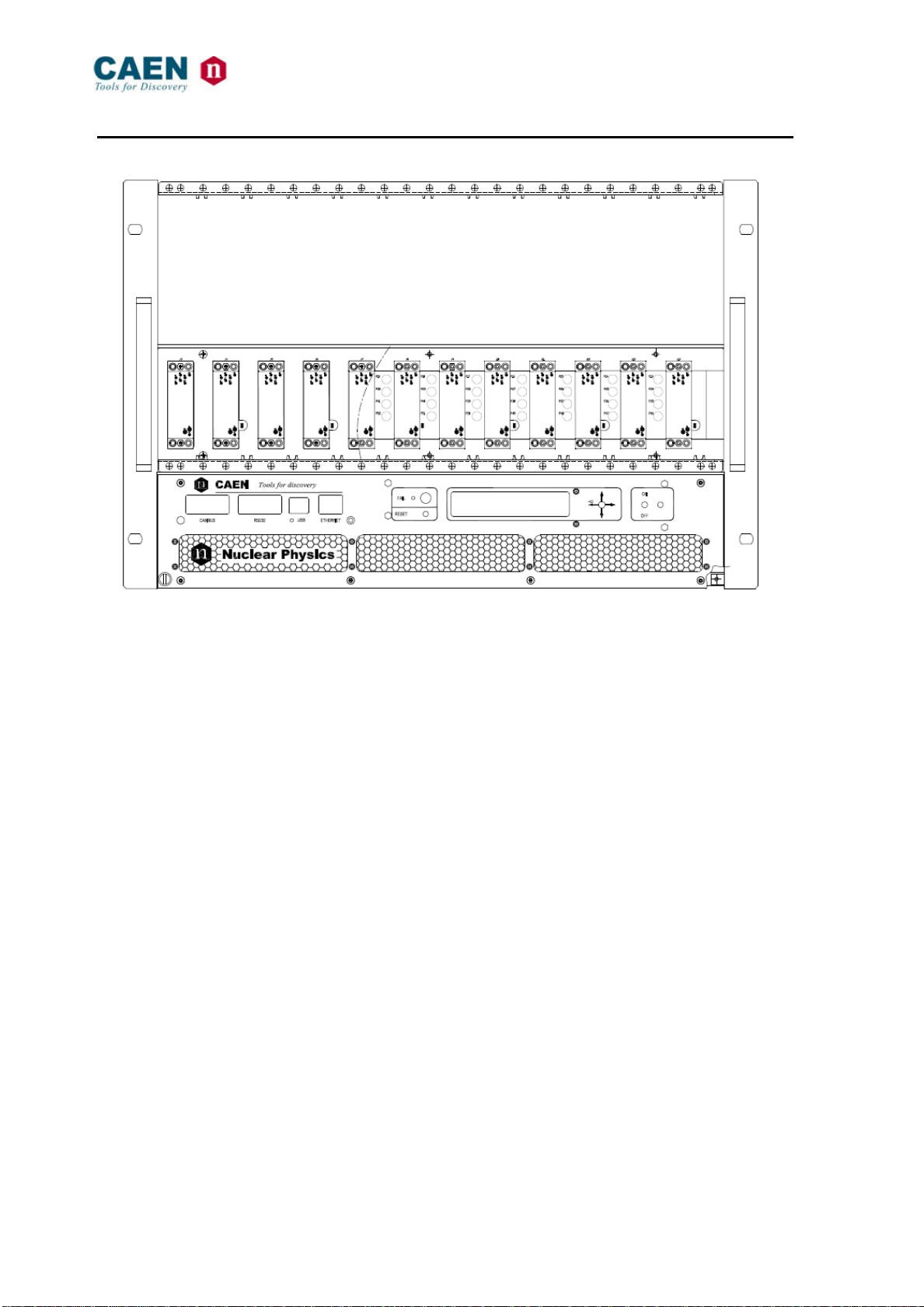
FIG.2.4: MOD.NIM8304 SIDE VIEW (POWER SUPPLY REMOVED)..........................................................13
FIG.2.5: MOD N8304 SMART NIM FAN UNIT FRONT VIEW.....................................................................14
FIG.2.6: MOD N8304 SMART NIM FAN UNIT TOP VIEW.........................................................................14
FIG.2.7: MOD N8304 SMART NIM FAN UNIT TOP VIEW.........................................................................14
FIG.2.8: MOD N8304 SMART NIM FAN UNIT TOP VIEW.........................................................................15
FIG.2.9: BACKPLANE NIM CONNECTOR EXTERNAL VIEW........................................................................15
FIG.2.10: MOD NIM8304 BIN POWER CONNECTORS.............................................................................16
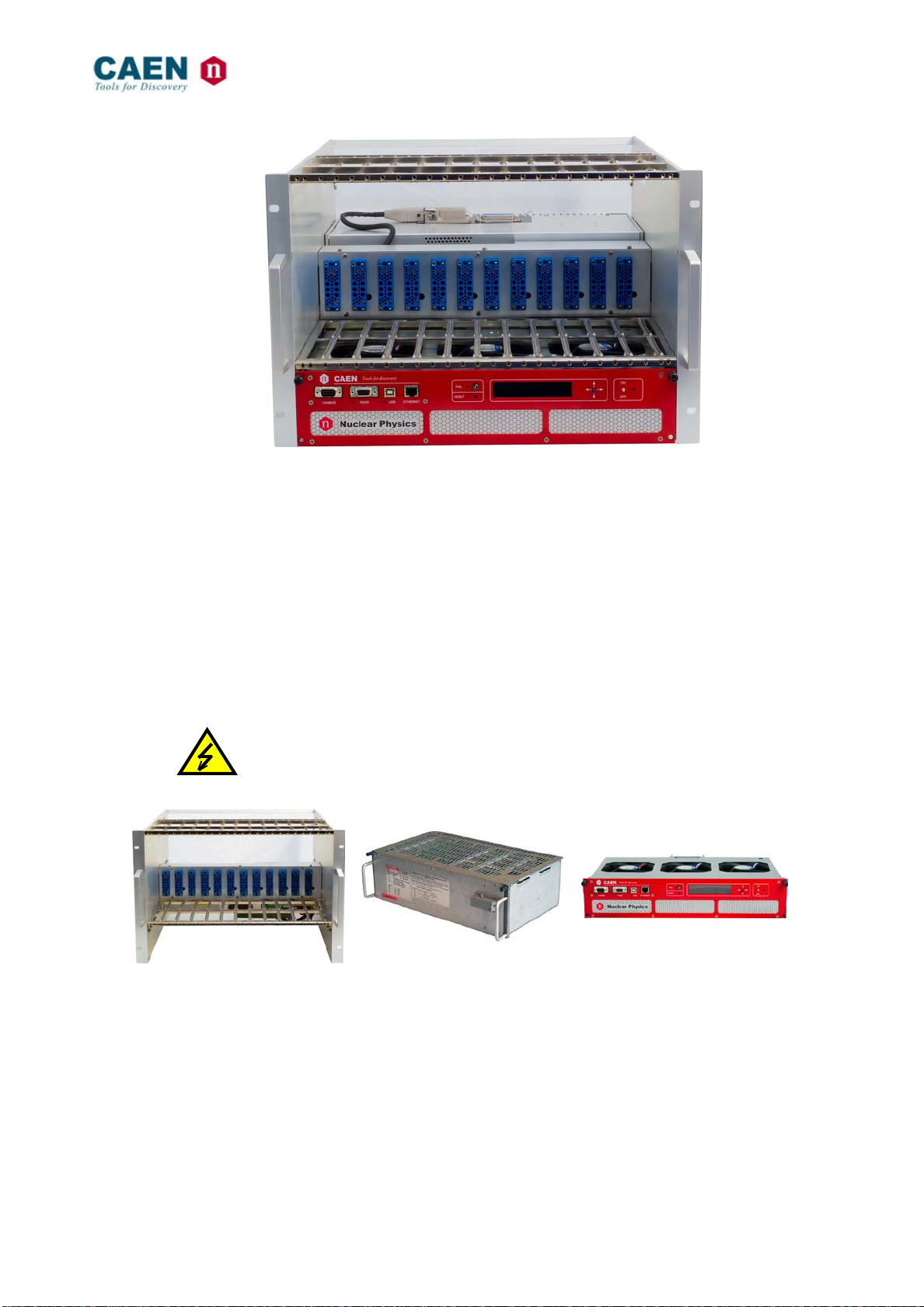
FIG.3.1: MOD.NIM8304 POWER SUPPLIES FRONT AN REAR VIEW .......................................................17
FIG.3.2: MOD.NIM8304 POWER SUPPLIES COMPONENTS....................................................................18
FIG.3.3: POWER CONNECTOR CONFIGURATION ....................................................................................18
FIG.3.4: HIRSCHMANN CONNECTOR .....................................................................................................19
FIG.3.5: POWER MODULE RIPPLE AND NOISE MEASURED AT THE OUTPUT CONNECTOR (@ ±6V, 90A) ....22
FIG.3.6: POWER MODULE RIPPLE AND NOISE MEASURED AT LOAD 0.5 M WIRE (@±6V, 90A) .................22
FIG.3.7: POWER MODULE RIPPLE AND NOISE AT OUTPUT CONNECTOR (@ ±12V, 23A; @±24V, 11A)....23
FIG.3.8: :POWER MODULE RIPPLE AND NOISE AT LOAD 0.5 M WIRE (@ ±12V, 23A; @±24V, 11A)........23
FIG.3.9: FAN TRAY /CONTROL CONNECTOR (9-PIN DSUB FEMALE).....................................................24
FIG.3.10:SENSE /SIGNAL CONNECTOR (37-PIN DSUB FEMALE) .........................................................24
FIG.4.1: MOD.NIM8304 FAN TRAY FRONT VIEW................................................................................25
FIG.4.2: CAN BUS CONNECTOR..........................................................................................................26
FIG.4.3: RS-232 CONNECTOR (CONNECTOR 9-PIN DSUB FEMALE)9-PIN DSUB MALE ..........................26
FIG.4.4: ETHERNET LAN CONNECTOR .................................................................................................27
FIG.4.5: FAIL OUTPUT CIRCUIT ............................................................................................................27
FIG.4.6: FAIL SIGNAL TIMING...............................................................................................................28
FIG.5.1: POWER SUPPLY INSERTION.....................................................................................................31
FIG.6.1: MOD.NIM8304_MANAGER OPEN WINDOW.............................................................................36
FIG.6.2: MOD.NIM8304_MANAGER COONECTION MENU......................................................................36
FIG.6.3: MOD.NIM8304_MANAGER CONNECTION WINDOW .................................................................36
FIG.6.4: MOD.NIM8304_MANAGER STATUS/SET WINDOW (POWER OFF) .............................................37
FIG.6.5: MOD.NIM8304_MANAGER STATUS/SET WINDOW (POWER ON)..............................................37
FIG.6.6: MOD.NIM8304 TERMINAL START UP WINDOW .......................................................................38
FIG.6.7: MOD.NIM8304 TERMINAL MENU WINDOW..............................................................................39
FIG.6.8: MOD.NIM8304 PS &FAN STATUS MENU WINDOW.................................................................39
FIG.6.9: MOD.NIM8304 PS &GENERAL STATUS WINDOW...................................................................40
FIG.6.10: MOD.NIM8304 FIRMWARE UPDATE WINDOW 1 ....................................................................41
FIG.6.11: MOD.NIM8304 FIRMWARE UPDATE WINDOW 2 ....................................................................41
FIG.6.12: MOD.NIM8304 FAN UNIT FIRMWARE UPDATE WINDOW........................................................41
FIG.6.13: MOD.NIM8304 FAN UNIT FIRMWARE UPDATE WINDOW........................................................41

Document type:
Title:
Revision date:
Revision:
User's Manual (MUT)
Mod. NIM8304 12 slot 7U(5+2) Switching NIM Crate
14/04/2014
3
NPO:
Filename:
Number of pages:
Page:
00121/09:N8304.MUTx/03
NIM8304_REV3.DOC
44
6
LIST OF TABLES
TABLE 1.1: MOD.NIM8300 VERSIONS ....................................................................................................7
TABLE 2.1: MOD.NIM8304 TECHNICAL SPECIFICATIONS.........................................................................9
TABLE 3.1: HIRSCHMANN CONNECTOR CABLING.....................................................................................19
TABLE 3.2: POWER FACTOR CORRECTION MODULE SPECIFICATIONS .....................................................19
TABLE 3.3: POWER MODULE (±6V)TECHNICAL SPECIFICATIONS ............................................................20
TABLE 3.4: POWER MODULE (±12V)TECHNICAL SPECIFICATIONS ..........................................................20
TABLE 3.5: POWER MODULE (±24V)TECHNICAL SPECIFICATIONS ..........................................................21
TABLE 5.1: MOD.NIM8304 FAN TRAY MENU.......................................................................................33
TABLE 5.2: MOD.NIM8304 FAN TRAY SUB MENU................................................................................34

Document type:
Title:
Revision date:
Revision:
User's Manual (MUT)
Mod. NIM8304 12 slot 7U(5+2) Switching NIM Crate
14/04/2014
3
NPO:
Filename:
Number of pages:
Page:
00121/09:N8304.MUTx/03
NIM8304_REV3.DOC
44
7
1. General description
1.1 NIM8300 crate series
The NIM8300 crate series consists of a NIM mechanics and a pluggable power supply
(150W, 300W, 600W, 1kW and 2kW available). NIM standard, despite of its age, is still a
great choice for building a small and flexible setup for high resolution measurements with
analogue electronics such as amplifiers, ADCs, timing and logic units and also LV/HV
power supplies.
Table 1.1: Mod. NIM8300 versions
Form factor
Power
Ordering Option
±6V
±12V
±24V
5U 12 slot (10 free)
short size 150 W WNIM8302150W 5 A 3 A 1.5 A
5U 12 slot std size
300 W WNIM8303300W 17 A 3.4 A 3,4 A
600 W
WNIM8303600W 45 A 8 A 8 A
WNIM8303600Y 20 A 15 A 4 A
WNIM8303600Z 45 A 18 A
7U 12 slot std size
300 W WNIM8304300W 17 A 3.4 A 3.4 A
600 W
WNIM8304600W 45 A 8 A 8 A
WNIM8304600Y 20 A 15 A 4 A
WNIM8304600Z 45 A 18 A
1.1kW – 2.2kW switching WNIM8304XAAA 90 A 23 A 11 A
1.2 NIM8304 Overview
The CAEN Mod. NIM8304 is a 7U (5+2) full size NIM crate (19”-12 slot) with switching
1.1kW US and 2.2kW EU power supplies. The units are ventilated by a pluggable 2U fan
unit.
Safety features include: short circuit protection, Over / Under voltage protection, Over
temperature protection. Remote monitoring and control take place through CAN bus,
Ethernet, USB and RS232 interfaces. The crates are also SBC controlled via graphic
OLED Display. User-friendly control software completes the NIM 8304 features. The Unit
is powered by 115 or 230 Vac, 50 ÷ 60 Hz.

Document type:
Title:
Revision date:
Revision:
User's Manual (MUT)
Mod. NIM8304 12 slot 7U(5+2) Switching NIM Crate
14/04/2014
3
NPO:
Filename:
Number of pages:
Page:
00121/09:N8304.MUTx/03
NIM8304_REV3.DOC
44
8
Fig. 1.1: The Mod. NIM8304 12-slot 7U NIM crate
The crate is based on a modularity concept and it has been divided into three detachable
parts
-
The Subrack (
Bin and NIM
connector
): NIM 7U Bin, 12 slot
-
The Power Supply: NIM switching Power supply (±6V 90A, ±12V 23A,
±24V 11A)
-
The ventilation and control unit
(Fan Tray):
N8304F Smart NIM Fan Unit, 3-
fold fan tray,
alphanumeric display with TCP-IP, CANbus, RS232
and USB 2.0
The Unit is powered by 92 ÷264 Vac, 50 ÷ 60 Hz, power factor 0.98% (230VAC).
Fig. 1.2: Modularity of Mod. NIM8304 12-slot 7U NIM crate

Document type:
Title:
Revision date:
Revision:
User's Manual (MUT)
Mod. NIM8304 12 slot 7U(5+2) Switching NIM Crate
14/04/2014
3
NPO:
Filename:
Number of pages:
Page:
00121/09:N8304.MUTx/03
NIM8304_REV3.DOC
44
9
2. Technical specifications
2.1 Technical specification table
Table 2.1: Mod. NIM8304 Technical Specifications
Mechanics
19” x 7U (5+2) bin, 12 slot, 2U space for fan tray
Mains input
92 ÷264 Vac, 50 ÷ 60 Hz, power factor 0.98% (230VAC)
Max. Total Output Power 1100 W @ 100 Vac
2200 W @ 211 Vac
Power requirements
1450 W @ 100 Vac
2850 W @ 211 Vac
Interface
RS 232, USB (2.0), CAN bus, Ethernet
Fuse
External 16 A, type B/C
Output power
EU US
90A @ ±6V
23A @ ±12V
11A @ ±24V
45A @ ±6V
11.5A @ ±12V
5.5A @ ±24V
Isolation
CE acc. to EN 60950
Load Regulation < 10 mV for 0-100% load change @ ± 6V
< 15 mV for 0-100% load change @ ±12 V
< 15 mV for 0-100% load change @ ±24 V
Noise and ripple (full load)
Output
Max
Typical
±6V
< 10 mVpp, <2
mVrms
6.0 mVpp, 1.5
mVrms
±12V
< 15 mVpp, <2
mVrms
10 mVpp, 1.0
mVrms
±24V
< 15 mVpp, <2
mVrms
10 mVpp, 1.0
mVrms
Temperature sensors Power Supply Control: nr. 1
FAN Unit: nr. 1
Backplane: nr. 6 (optional)
Over Voltage Protection
Trip Off when the output voltage > 103% ÷ 120%
(programmable) of set voltage
Under Voltage Protection
Trip Off when the output voltage < 80% ÷ 97%
(programmable) of set voltage
Over Current Protection Trip Off when the current > programmable Iset value
Over Temperature Protection
Trip Off when temperature of a single Power Supply
block > 90° C
Signaled:
-temperature FAN Unit > 50°C
-temperature Power Supply Control > 65° C
Operation 0÷50°C without derating,
Cooling Airflow: 540 m³/h (at maximum fan speed)
Firmware
NIM8304 firmware can be upgraded via Ethernet

Document type:
Title:
Revision date:
Revision:
User's Manual (MUT)
Mod. NIM8304 12 slot 7U(5+2) Switching NIM Crate
14/04/2014
3
NPO:
Filename:
Number of pages:
Page:
00121/09:N8304.MUTx/03
NIM8304_REV3.DOC
44
10
2.2 Technical drawings
Fig. 2.1: Mod. NIM8304 Front view

Document type:
Title:
Revision date:
Revision:
User's Manual (MUT)
Mod. NIM8304 12 slot 7U(5+2) Switching NIM Crate
14/04/2014
3
NPO:
Filename:
Number of pages:
Page:
00121/09:N8304.MUTx/03
NIM8304_REV3.DOC
44
11
Fig. 2.2: Mod. NIM8304 Rear view (Power Supply removed)

Document type:
Title:
Revision date:
Revision:
User's Manual (MUT)
Mod. NIM8304 12 slot 7U(5+2) Switching NIM Crate
14/04/2014
3
NPO:
Filename:
Number of pages:
Page:
00121/09:N8304.MUTx/03
NIM8304_REV3.DOC
44
12
Fig. 2.3: Mod. NIM8304 Top view

Document type:
Title:
Revision date:
Revision:
User's Manual (MUT)
Mod. NIM8304 12 slot 7U(5+2) Switching NIM Crate
14/04/2014
3
NPO:
Filename:
Number of pages:
Page:
00121/09:N8304.MUTx/03
NIM8304_REV3.DOC
44
13
Fig. 2.4: Mod. NIM8304 side view (Power Supply removed)

Document type:
Title:
Revision date:
Revision:
User's Manual (MUT)
Mod. NIM8304 12 slot 7U(5+2) Switching NIM Crate
14/04/2014
3
NPO:
Filename:
Number of pages:
Page:
00121/09:N8304.MUTx/03
NIM8304_REV3.DOC
44
14
Fig. 2.5: Mod N8304 Smart NIM Fan Unit Front view
Fig. 2.6: Mod N8304 Smart NIM Fan Unit Top view
Fig. 2.7: Mod N8304 Smart NIM Fan Unit Top view

Document type:
Title:
Revision date:
Revision:
User's Manual (MUT)
Mod. NIM8304 12 slot 7U(5+2) Switching NIM Crate
14/04/2014
3
NPO:
Filename:
Number of pages:
Page:
00121/09:N8304.MUTx/03
NIM8304_REV3.DOC
44
15
Fig. 2.8: Mod N8304 Smart NIM Fan Unit Top view
2.3 Crate Backplane
The backplane is equipped with 12 high-quality long-life NIM connectors, which are
completely parallel-wired.
Fig. 2.9: Backplane NIM connector external view

Document type:
Title:
Revision date:
Revision:
User's Manual (MUT)
Mod. NIM8304 12 slot 7U(5+2) Switching NIM Crate
14/04/2014
3
NPO:
Filename:
Number of pages:
Page:
00121/09:N8304.MUTx/03
NIM8304_REV3.DOC
44
16
2.4 NIM8304 Bin Power connector
Fig. 2.10: Mod NIM8304 Bin power connectors
Pin Specification
10, 11, 13, 14, 15, 16, 17,18 6mm, 100A max
1,2,4,5 8mm, 230A max

Document type:
Title:
Revision date:
Revision:
User's Manual (MUT)
Mod. NIM8304 12 slot 7U(5+2) Switching NIM Crate
14/04/2014
3
NPO:
Filename:
Number of pages:
Page:
00121/09:N8304.MUTx/03
NIM8304_REV3.DOC
44
17
3. Power Supply section
The CAEN NIM Power Supply is micro-processor controlled switching power supply,
which provides extremely low noise output voltage.
Fig. 3.1: Mod. NIM8304 Power Supplies Front an Rear view
the NIM8304 power supplies are composed of the following modules ( see Fig. 3.2.)
-Power Factor Correction module (PFC)
-Power modules
-Power supply controller
The power modules are readily replaceable. The maximum output power is 1100÷2200W
with 92 ÷ 264 V input voltage.

Document type:
Title:
Revision date:
Revision:
User's Manual (MUT)
Mod. NIM8304 12 slot 7U(5+2) Switching NIM Crate
14/04/2014
3
NPO:
Filename:
Number of pages:
Page:
00121/09:N8304.MUTx/03
NIM8304_REV3.DOC
44
18
Fig. 3.2: Mod. NIM8304 Power Supplies components
3.1 Power Connector section
Fig. 3.3: Power Connector configuration
3.2 Power Factor Correction Module (PFC)
The mains input includes a Power Factor Correction Module (PFC) with main filters, soft
start- circuit and fuses. an external fuse or circuit breaker has to be installed with a
capability of 16A.
The AC input module is permanently powered after connecting the unit to the AC- mains.
Switch ON/OFF activates only the DC on/off function of the power inverter modules.

Document type:
Title:
Revision date:
Revision:
User's Manual (MUT)
Mod. NIM8304 12 slot 7U(5+2) Switching NIM Crate
14/04/2014
3
NPO:
Filename:
Number of pages:
Page:
00121/09:N8304.MUTx/03
NIM8304_REV3.DOC
44
19
Turning on the power supply all voltages reach the nominal values nearly simultaneously
within 50 ms whereby the voltage versus time curve shows a monotonic behavior. The
start-off-time which corresponds to a value of 10% of the nominal voltages is reached
after 50 ms. The turn-on inrush current is limited by a soft start-circuit to a maximum
value of 16 A.
The power modules are readily replaceable. The maximum output power is 1200÷2530W
with 92 ÷ 264 Vac input voltage.
3.3 Mains Voltage and Connection
The Power supplies are equipped with a “World”- mains input, which works properly from
92Vac up to 264Vac and within a frequency range of 50 to 60Hz. Before connecting to the
mains please double-check correspondence. Mains input connection at the power supply
side is done with a 3-pin “Hirschmann” 16 A connector or power terminals.
Fig. 3.4: Hirschmann connector
Table 3.1: Hirschmann connector cabling
Hirschmann pin nr. Signal Description Color of the Wire
Pin 1 L Phase black or brown
Pin 2 N Return, Neutral blue
Pin 3 not connected
Earth PE Protective Earth green/yellow
3.4 Power Supply specifications
3.4.1 Power Factor Correction Module
Table 3.2: Power Factor Correction Module specifications
Input
Voltage Range
92 ÷ 264 Vac Frequency 50 ÷ 60 Hz
Inrush Current
<16 A @ 230 Vac
Fuse
External 16A type B/C
Power Factor
> 0.98 @ Output Power > 1 kW

Document type:
Title:
Revision date:
Revision:
User's Manual (MUT)
Mod. NIM8304 12 slot 7U(5+2) Switching NIM Crate
14/04/2014
3
NPO:
Filename:
Number of pages:
Page:
00121/09:N8304.MUTx/03
NIM8304_REV3.DOC
44
20
Output
Maximum Total Output
Power
1200÷2530W with 92 ÷ 264 Vac input voltage
Turn on Delay
50 ms to 100% of voltage, monotonic rise
Efficiency
75% ÷ 85% @ 230 Vac configuration dependent
Isolation CE EN 60950
Input to Output
3000 Vac
Input to GND
1500 Vac
3.4.2 - Power Modules
The power modules are readily replaceable.
Each module is equipped with temperature sensors for Over Temperature Protection.
Table 3.3: Power Module (±6V) technical specifications
Voltage
±6V
Current
90 A
Rise Time
<50 ms to 100% of voltage, monotonic rise
Ripple
< 10 mVpp(1) Typ: 6.0 mVpp(1) (see Fig. 3.5)
< 5 mVpp
(2)
Typ: 2.5 mVpp
(2)
(see Fig. 3.6)
Noise
<2 mVrms(1) Typ: 1.5 mVrms(1) (see Fig. 3.5)
<1.5 mVrms
(2)
Typ: 0.5 mVrms
(2)
(see Fig. 3.6)
Voltage Accuracy
± 20 mV
Minimum Load
No
Load Regulation
< 10 mV (sense) for 0-100% load change
Transient Response Recovery
< 100 mV @ ±25A current step change
6 ms for recovery to ±1% of set voltage @ 25A to 0A current step change
0.5 ms for recovery to ± 1% of set voltage @ ±25A current step change
0.7 ms for recovery to ± 0.1% of set voltage @ ±25A current step change
Over Voltage Protection
When the output voltage > 103% ÷ 120% (programmable) of set voltage
Under Voltge Protection
When the output voltage < 80% ÷ 97% (programmable) of set voltage
Over Current Protection
When the current > programmable Iset value
Short Circuit Protection
<125 A @ 7 Vout
Over Temperature Protection
When the Power module temperature > 90° C
flicker immunity
< 50 ms
Environment Temperature
0° to 50° Operational
Table 3.4: Power Module (±12V) technical specifications
Voltage
±12V
Current
23 A
Rise Time
<50 ms to 100% of voltage, monotonic rise
Ripple < 15 mVpp
(1)
Typ: 10 mVpp
(1)
(see Fig. 3.7)
< 10 mVpp
(2)
Typ: 5 mVpp
(2)
(see Fig. 3.8)
Noise
< 2 mVrms(1) Typ: 1.0 mVrms(1) (see Fig. 3.7)
< 1.5 mVrms
(2)
Typ: 0.5 mVrms
(2)
(see Fig. 3.8)
Voltage Accuracy
± 20 mV
Minimum Load
No
Table of contents
Other Caen Power Supply manuals
Popular Power Supply manuals by other brands

VOLTCRAFT
VOLTCRAFT FTPS12-27W2.5 operating instructions

ESAB
ESAB EPP-362 instruction manual

Cisco
Cisco 5508 - Wireless Controller - Network Management... datasheet

SLAT
SLAT AES operating instructions

Altronix
Altronix ALTV248220 Series installation guide

Cobalt Digital Inc
Cobalt Digital Inc DCP-SPS12 quick start guide