manuals.online logo
Brands
  1. Home
  2. •
  3. Brands
  4. •
  5. CALECTRO
  6. •
  7. Smoke Alarm
  8. •
  9. CALECTRO UG-7-A6O-120V Manual

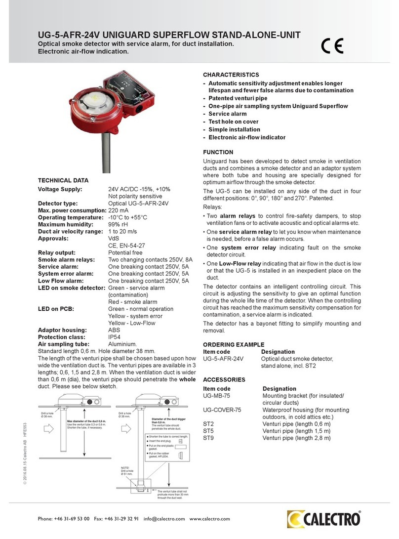
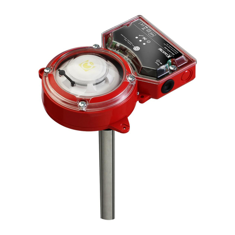
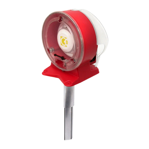
CALECTRO UG-7-A6O-120V Manual

UG-7-A6O Installation manual page 1
HFE716 Version: 14 Date: 2014-03-24
UG-7-A6O-24V and UG-7-A6O-120V Installation and maintenance manual
Box 4113 •426 04 Västra Frölunda •SWEDEN
[email protected] •www.calectro.com
________________________________________________________________________________________
Specifications:
Operating temperature: 32°F (0°C) to 100°F (38°C),
Storage temperature: -22°F (-30°C) to 158°F (70°C)
Humidity: 0% to 95% Relative humidity
Air Velocity: 100 ft/min (0.51 m/sec.) - 4000 ft/min (20.32 m/sec).
Footprint dimensions: L: 10.98 in (279 mm) / W: 6.49 in (165 mm) / D: 3.26 in (83 mm)
Weight: UG-7-A6O-24V: 0,84kg / UG-7-A6O-120V: 1kg
Electrical UG-7-A6O-24V UG-7-A6O-24V UG-7-A6O-120V
Power suppl
y
volta
g
e : 24Vdc (-5 / +20%) 24Vac (±10%) 50-60Hz 110-120Vac 50-60Hz
Reset time (b
y
power down): 1 sec. max.
Power up time: 1 minute
Sensitivit
y
:
N
ominal sensitivit
y
0.96-1.2 %/f
t
Current requirements
Max. standby current (no
external equipment attached):
42mA 82mA 31mA (at 120Vac)
Max. alarm current: 83mA 145mA 42mA (at 120Vac)
Lin
k
curren
t
: 5mA
Total max auxiliary current
output on terminals 2 and 5:
Without linked detectors: 30mA, with linked detectors: 25mA
Contact ratings
Alarm initiation contacts (SPST) 1.0A @ 24VDC (resistive)
1.0A
@
120VAC (resistive)
Supervisory contacts (SPST) 1.0A @ 24VDC (resistive)
1.0A
@
120VAC (resistive)
Alarm auxiliary contacts (DPDT) 10A @ 30VDC (resistive)
10A @ 250VAC (resistive)
½ HP @ 240VAC
¼ HP
@
120VAC
PRIOR TO INSTALLING YOUR DUCT DETECTOR
Read this installation manual which provides information on detector placement, wiring, test and maintenance.
This manual is also available online at www.calectro.com.
Follow the installation instruction in the installation manual, and all applicable local codes including NFPA 72,
NFPA 90A, and NEMA Guide for Proper Use of Smoke Detectors in Duct Applications,
TABLE OF CONTENTS
[1] Limitations of Duct Smoke Detectors
[2] Overview
[3] General Description
[4] Duct Smoke Detector Kit Contents
[5] Installation
[6] Field Wiring Installation Guidelines
[7] Measurement Tests
[8] Detector condition Indication
[9] Confirmation of Operation
[10] Detector replacement and cleaning
UG-7-A6O Installation manual page 2
HFE716 Version: 14 Date: 2014-03-24
[1] LIMITATIONS OF DUCT SMOKE DETECTORS
The National Fire Protection Association has established that DUCT DETECTORS MUST NOT BE USED AS
A SUBSTITUTE FOR OPEN AREA DETECTOR PROTECTION as a means of providing life safety. Nor are
they a substitute for early warning in a building’s regular fire detection system. Calectro AB supports this
position and strongly recommends that the user read NFPA Standards 90A, 72, and 101. UG-7-A6O is listed per
UL 268A. This device will not operate without electrical power supplied to it. Fire situations may cause an
interruption of power. The system safeguards should be discussed with your local fire protection specialist. This
device will not sense smoke unless the ventilation system is operating and the cover is installed. For this detector
to function properly, it MUST be installed according to the instructions in this manual. Furthermore, the detector
MUST be operated within ALL electrical and environmental specifications listed in this manual. Failure to
comply with these requirements may prevent the detector from activating when smoke is present in the air duct.
[2] OVERVIEW OF UG-7-A6O COMPONENTS
Figure 1.
ITEM NO. DESCRIPTION
1 Test hole plu
g
2 4 x Delta PT 60x30
3 Cover
g
aske
t
4 Cover / label area
5 Smoke detecto
r
6 10 x Delta PT 40x8
7 Smoke detector base
8 Electronics PCB
9 Inner cove
r
10 Base pa
r
t
11 Seal
g
aske
t
12 O-rin
g
13 Samplin
g
tube
14 Outer cove
r
15 End plu
g
16 Test/Reset button
g
aske
t
A1 * Diverte
r
* Item A1: Diverter UG-7-DV-T2
for air velocities below 300ft/m.
Assembly: Remove the cover (item
4, Figure 1), place the diverter on
the air inlet part so it covers half the
smoke detector (item 5).
Note: Do not use the diverter for
application that exceeds 300 f/m.
1
3
2
4
6
8
7
9
10
14
11
16
13
5
12
15
A1
UG-7-A6O Installation manual page 3
HFE716 Version: 14 Date: 2014-03-24
[3] GENERAL DESCRIPTION
Smoke entering the duct system will be dispersed throughout the whole building. The UG-7-A6O Duct Detectors
utilizes the photoelectric sensing method and is designed to sense the existence of smoke in the duct. This design
of the housing along with the detector technology is capable of detecting unsafe conditions by sampling the air
through the duct, when the smoke is detected, it will emit a signal that will create the urgency for proper action
to be taken to turn off circulating fans, blowers and any other auxiliary devices that are connected to the system.
The actions taken will enable the management of hazardous smoke through the entire space that is being
protected by the duct detection arrangement.
The UG-7-A6O has two versions that operates with 24 VDC/VAC or 120 VAC. The UG-7-A6O-24V for the 24
VDC/VAC and the Model UG-7-A6O-120V for the 120 VAC versions. Alarm and supervisory relay contacts
are accessible to interface with control panel, HVAC control, and multiple auxiliary functions including turning
off the fan.
[3.1] UG-7-A6O FEATURES:
- High efficient single sampling tube
- Easy to install
__________________________________________________________________________________________
[4] DUCT SMOKE DETECTOR KIT CONTENTS
1. Detector/power board assembly and covers
2. Three metal screws for mounting
3. One sampling tube end plug
4. Installation manual (this document)
NOTE: Cable glands are not included in the kit.
NOTE: A sampling tube must be ordered to complete the installation. The sampling tube should penetrate
approx 90% of the width of the duct. See Table 4.1 to determine the sampling tube required for different duct
widths.
Table 4.1
Samplin
g
tube Len
g
th of samplin
g
tube
ST1 1 ft.
ST2 2 ft.
ST5 5 ft.
ST9 9 ft.
At velocities below 300ft./min the model UG-7-DV-T2 diverter (Figure 1: Item A1, ordered separately) needs
to be installed for normal operation. For velocities above 300ft./min the model UG-7-T2 diverter is not required
for normal operation.
[5] INSTALLATION
Check the air flow direction and velocity. The UG-7-A6O detector is designed to be used in air handling systems
with air velocities of 100 to 4000 feet per minute. Duct widths from 6 inches to 9 feet can be accommodated.
Follow engineering specifications to ensure that the air velocity in the duct falls within these parameters. The air
velocity can be verified by the use of a velocity meter to check the air velocity in the duct.
NOTE: Avoid mounting in places where condensation problems could arise, such as cold attics or outdoors.
[5.1] DETERMINE MOUNTING LOCATION ON THE DUCT
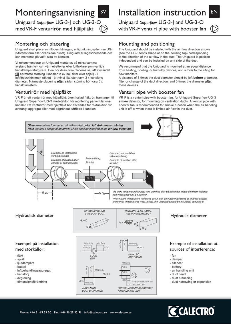
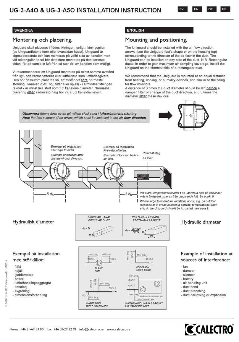
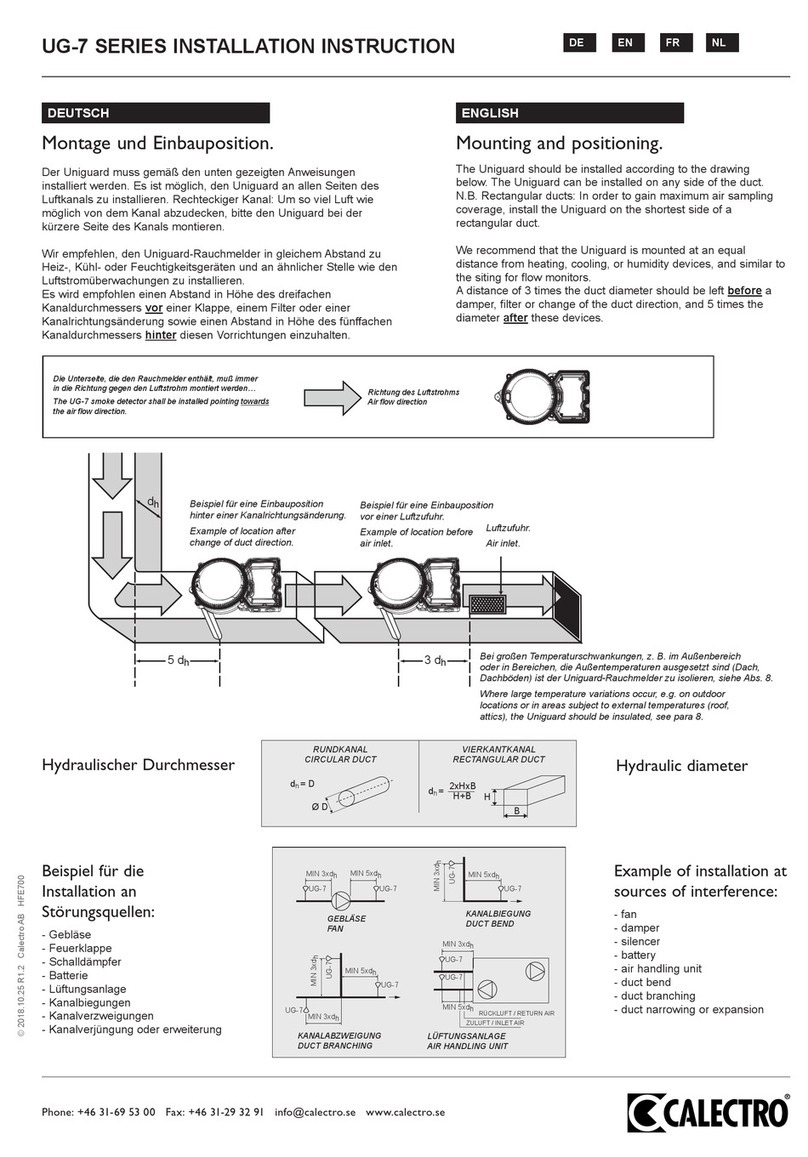
The UG-7-A6O must be installed with the duct air flow direction according to Figure 2.
The UG-7-A6O can be installed on any side of the duct.
UG-7-A6O Installation manual page 4
HFE716 Version: 14 Date: 2014-03-24
Figure 2
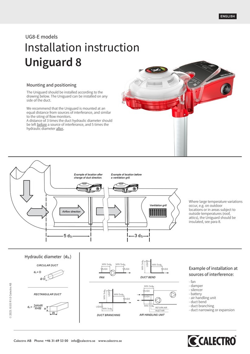
We recommend that the UG-7-A6O is mounted on a distance of approximately 3 times the duct diameter before
an obstruction such as dampers, filters or bends, and approximately 5 times the diameter after these obstructions
as shown in Figure 3.
Figure 3
[5.2] MOUNTING OF DETECTOR ON THE DUCT
 Drill a 1 ½ inch (38 mm) hole where the detector is to be mounted.
 Measure the diameter of the duct.
 The sampling tube should penetrate approximately 90% of the width of the duct. See Section 4 Table
4.1.
 If necessary, shorten the sampling tube and insert the end plug. Figure 5.
NOTE: When installing sampling tubes longer than 2 ft. see Section 5.4
 Insert the sampling tube in the Base Part. Figure 6.
 Secure the sampling tube by fastening the screw. Figure 7.
 Insert the sampling tube in the duct and secure the UG-7-A6O to the duct using the three provided
metal screws (Arrows 1,2 and 3). Figure 8.
Figure 5
Do not cut this en
d
End plu
g
Air flow
direction
Mountin
g
position
Ventilation duct
UG-7-A6O Installation manual page 5
HFE716 Version: 14 Date: 2014-03-24
Figure 6 Figure 7 Figure 8
[5.4] INSTALLATION OF SAMPLING TUBE LONGER THAN 2 FT.
Strong vibrations can arise inside a duct due to the air currents. When the diameter of the duct is larger than 2 ft.
the sampling tube should penetrate the whole duct. Drill a 2 inch hole in the opposite side of the duct. Mount the
rubber gasket HFU204* in the hole. Put on the long plastic end plug HFU640* on the sampling tube. The
sampling tube should not protrude more than 1 inch through the duct wall in order to avoid air leakage. Figure
12.
* Delivered together with sampling tubes of 5 and 9 ft.
Figure 12
[6] FIELD WIRING INSTALLATION GUIDELINES
All wiring must be installed in compliance with the National Electrical Code and the local codes having
jurisdiction. Appropriate wire gauges should be used. Color-Code the conductors used to connect smoke
detectors to control panels and accessory devices to avoid wiring problems. Improper connections can prevent a
system from operating and responding properly in the event of a fire condition. A minimum 18 gauge wire must
be used for signal wiring (when interconnecting detectors or between detectors and auxiliary devices)
[6.1] CONDUIT ENTRIES AND WIRING
The UG-7-A6O is factory prepared with one conduit opening. In case more than one opening is needed, carefully
remove the round plastic wall in the selected entry and insert a conduit connector. If the factory prepared
opening is not used, it must be properly sealed. Figure 14a.
Remove the four screws and lift of the cover according to Figure 14b in order to be able to make the wiring.
Place the cover back on the housing, and tighten the four screws – for proper mounting, please use torque: 1.8-
1.9 Nm.
[6.2] DETECTOR LINKING
UG-7-A6O has linking function that allows interconnection between maximum 100 units. All linked detectors
operate independently from each other. The linking function is to be seen as an extra prevention feature that
could close dampers or stop fans further away in the ventilation system, before the smoke has reached the places
were the linked detectors are installed. Maximum 200 yards cable length between each detector. The detector
link circuit must be a loop. This means that the last linked detector must be connected with the first detector.
Linking function: When one of the linked UG-7-A6O goes into smoke alarm, all other detectors AUX relays are
activated. The smoke alarm can only be reset on the UG-7-A6O that initiated the smoke alarm. This also resets
the AUX relays on all linked detectors in the loop. To test the linking function: press and hold the Test/Reset
button (or short circuit between terminals 6 and 1) for more than 10 seconds on one of the linked detectors.
For wiring information, see Figure 16.
NOTE: Disconnect the power when installing the detector linking function.
Consult Figure 16 and Table 8.1 for more information
1
2
3
HFU204
HFU640
>2 ft.
UG-7-A6O Installation manual page 6
HFE716 Version: 14 Date: 2014-03-24
Figure 14a Figure 14b
Figure 15
Table 6.1
1 GND / Detector Link ou
t
- Common
g
round for detector link out, +18V AUX and Test/Rese
t
2 Detector link out + 18Vdc at
smoke alarm, max load: 25-
30mA
Detector link out: 18Vdc out for AUX relay triggering of linked UG-7-
A6O detectors, and/or smoke alarm indication to external accessories.
Max load: without linked detectors: 30mA, with linked detectors: 25mA.
3 Detector link in -
Detector link in -
4 Detector link in + Detector link in +
5 + 18V AUX, max load:
25-30mA
18Vdc output: operation indication. Without linked detectors: 30mA,
with linked detectors: 25mA max load.
6 External Rese
t
/Tes
t
inpu
t
Shor
t
circuit to terminal 1 (GND) Test/Reset alar
m
.
7 Supervisor
y
rela
y
(NC) Indicates contaminated detector, removed detector or power failure.
8 Supervisor
y
rela
y
(Common) Indicates contaminated detector, removed de
t
ector or power failure.
9 Alarm rela
y
(NO) Smoke alarm rela
y
.
10 Alarm rela
y
(Common) Smoke alarm rela
y
.
11 Auxiliary relay 1 (NO) Auxiliary relay 1: smoke alarm, power failure, Test/Reset and linked
detectors.
12 Auxiliary relay 1 (Common) Auxiliary relay 1: smoke alarm, power failure, Test/Reset and linked
detectors.
13 Auxiliar
y
rela
y
1 (NC) Auxiliar
y
rela
y
1: smoke alarm, power failure, Test/Reset and linked
Factory prepared entry
for conduit connector.
* Extra conduit entries.
*
* *
Test/Reset butto
n
Detecto
r
LED
Power board LED
1: Green
2: Yellow
3: Yellow
4: Re
d
Test/Reset butto
n
Power suppl
y
UG-7-A6O Installation manual page 7
HFE716 Version: 14 Date: 2014-03-24
detectors.
14 Auxiliary relay 2 (NO) Auxiliary relay 2: smoke alarm, power failure, Test/Reset and linked
detectors.
15 Auxiliary relay 2 (Common) Auxiliary relay 2: smoke alarm, power failure, Test/Reset and linked
detectors.
16 Auxiliary relay 2 (NC) Auxiliary relay 2: smoke alarm, power failure, Test/Reset and linked
detectors.
17 Power supply 24Vac/dc for UG-7-A6O-24V version.
120Vac for UG-7-A6O-120V version
18 Power supply 24Vac/dc for UG-7-A6O-24V version.
120Vac for UG-7-A6O-120V version
Figure 16
NOTE 1: 24V Power Inputs accept a non-polarized 24VDC or 24VAC 50-60Hz (UG-7-A6O-24V version).
Connect power source to appropriate terminals of each detector. Power supply must not be connected to GND
(terminal 1).
NOTE 2: 120VAC Power Inputs accept 110-120VAC 50-60Hz (UG-7-A6O-120V). Connect power source to
appropriate terminals of each detector. See specifications for additional power supply information.
NOTE 3: Auxiliary contacts shown in standby position. Contacts switch during alarm as indicated by arrows.
Auxiliary contacts are not to be used for connection to the control panel. See specifications for contact ratings.
Fire control
panel
+
-
Alarm
initiation
loop
End-of-line
resistor
specified by
panel
manufacture
r
Alarm
initiation
contact in
standby
p
osition
9. N.O.
10. C.
7. 8.
C. N.C.
Supervisory and service alarm
contact
(contaminated or removed
smoke detector and power
failure)
Auxiliary contact
(fan shutdown, closing
of damper etc.)
First UG-7
detector in loop
17. 18.
Power input
UG-7-A6O-24V: 24Vac/dc
UG-7-A6O-120V: 120Vac
11. N.O.
13. N.C.
12. C.
14. N.O.
16. N.C.
15. C.
Alarm
initiation
contact in
standby
p
osition
9. N.O.
10. C.
7. 8.
C. N.C.
Supervisory and service alarm
contact
(contaminated or removed
smoke detector and power
failure)
Auxiliary contact
(fan shutdown, closing
of damper etc.)
Last UG-7
detector in loop
17. 18.
Power input
UG-7-A6O-24V: 24Vac/dc
UG-7-A6O-120V: 120Vac
11. N.O.
13. N.C.
12. C.
14. N.O.
16. N.C.
15. C.
1. GND / Detector
Link out -
2. Link out +
3. Link in -
4. Link in +
2. Link out +
3. Link in -
4. Link in +
1. GND / Detector
Link out -
UG-7-A6O Installation manual page 8
HFE716 Version: 14 Date: 2014-03-24
NOTE 4: Supervisory contacts indicates: removed, contaminated or power failure. Contacts shown in standby
position. Open contacts indicate a trouble condition. See specifications for contact ratings.
NOTE 5: Alarm Initiation contacts shown in standby position. Closed contacts indicate an alarm condition. See
specifications for contact rating.
NOTE 6: The detector link circuit must be a loop. This means that the last linked detector must be connected
with the first detector. Maximum 100 detectors in a link. Maximum cable length: 200 yards between each
detector. Disconnect the power when installing the detector linking function. Polarity must be maintained
between all linked detectors to obtain normal operation of the linking function.
[7] MEASUREMENT TESTS
[7.1] METHOD 1: AEROSOL SPRAY FOR AIR FLOW SPEED: 100-275 FPM
This test is aimed toward a system that operates between 100-275 FPM. Additional modifications will be
required for a system that operates at higher air velocities that exceeds 275 FPM. This will require drilling an
approximately ¼ inch (6.35mm) hole about 3 feet (0.914m) upstream from the duct detector. Measure the air
movement through the hole with a velocity meter while the air handler is on, the air velocity should be a
minimum of 100 FPM Introduce aerosol smoke into the duct through the ¼ inch (6.35mm) hole by following the
instruction on the smoke detector tester and wait approximately 2-3 minutes for the detector to alarm. The
detector alarm indicates that air is moving into the detector.
With the air handler on, push the Reset Button (repeatedly if necessary) until the UG-7-A6O remains in Standby
condition. This also indicates that the aerosol smoke is ventilated from the detector chamber. Once this operation
is completed, the ¼ inch (6.35mm) hole must be sealed off by applying duct tape.
NOTE: Aerosol smoke can be purchased from Home Safeguard Industries at homesafeguard.com, model HO-
25S Smoke Detector Tester. Proper use of the canned smoke agent will place the smoke detector in alarm mode.
Refer to the manufacture’s details and instructions for the proper use of the canned smoke agent.
[7.2] METHOD 2: LOW VELOCITY 100-500 FPM:
This test is intended for low-flow systems (100-500 FPM).
With the air handler on, measure the air velocity with an anemometer. The air speed must be100 FPM or
greater. Then use the Dwyer Transmitter (series 607) by following the details provided in figure 16B. The
pressure differential across the inlet port and outlet ports of the sampling tube shall be verified to be more than
0.01 inches of water. Measure the pressure difference between the inlet port and outlet ports on the sampling
tube with a Dwyer Series 607 Differential Pressure Transmitter. To verify sufficient sampling of ducted air, turn
the air handler on. Connect the leads of the meter to either side of the 1KΩ resistor. Allow unit to warm up for
15 seconds. With both HIGH and LOW pressure ports open to ambient air, measure and record the voltage drop
across the 1KΩ resistor (measurement A), typical reading is approximately 4V. Use flexible tubing to connect
the HIGH side of the transmitter to the inlet port of the sampling tube and the LOW side of the transmitter to the
outlet ports of the sampling tube. Measure and record the voltage drop across the 1KΩ resistor (measurement
B). Subtract the voltage recorded in measurement A from the voltage recorded in measurement B. The results
should be greater than 0.15 volts, and then this indicates that there is enough air flow through the duct smoke
detector for proper operation.
UG-7-A6O Installation manual page 9
HFE716 Version: 14 Date: 2014-03-24
Figure 16B
[7.3] METHOD 3 : AIR VELOCITY GREATER THAN 500 FPM:
First, verify the air speed is greater than 500 feet per minute by using the measurement method described in
method 1 above. With the air handler turned on, use a manometer to measure the differential pressure across the
inlet port and outlet ports of the sampling tube, this measurement shall be verified to be between 0.0028 to 1.49
inches of water. Please ensure that the end of the tube is completely sealed by use of a plug, or a duct tape in
order to obtain proper measurements.
[8] DETECTOR CONDITION INDICATION
Detector condition is indicated by the detector LED, and the corresponding LEDs on the power board. The
power board has four separate LEDs to indicate the status of the detector. Refer to Table 8.1 for more details.
Table 8.1
Status Description Detector
LED: red
Power board LED
number
Status of relays
1
Green 2
Yellow 3
Yellow 4
Red Terminals
open
Terminals
closed
Standby Detector in normal
operation
9-10
11-12
14-15
7-8
12-13
15-16
Maintenance Fixed LED 3: detector is
removed
Flashing LED 3:
detector is contaminated
7-8
9-10
11-12
14-15
12-13
15-16
Alarm Detector detects smoke 12-13
15-16
7-8
9-10
11-12
14-15
Trouble Power failure Off Off Off Off 7-8
9-10
12-13
15-16
11-12
14-15
Linked alarm
from other
UG-7-A6O
AUX relays are in alarm
mode due to smoke
alarm from linked UG-7-
A6O
9-10
12-13
15-16
7-8
11-12
14-15
UG-7-A6O Installation manual page 10
HFE716 Version: 14 Date: 2014-03-24
[9] CONFIRMATION OF OPERATION
[9.1] POWERING THE UNIT
Apply power to terminals 17 and 18:
24 VAC/DC for UG-7-A6O-24V version.
120 VAC for UG-7-A6O-120V version.
[9.2] PERFORM DETECTOR CHECK
Verify that the UG-7-A6O is installed according to this manual and that it is in Standby Status according to
Table 8.1.
[9.3] SENSITIVITY VERIFICATION
The UG-7-A6O indicates that the smoke detector is contaminated and should be replaced. The indications are:
Flashing the amber LED number 3 and opening of the relay contact terminals 7 and 8.
[9.4] DETECTOR CLEANING PROCEDURES
Notify the local and responsible authorities that maintenance is being conducted on the smoke detector system,
and that the system will be out of service until maintenance is completed. Disable the zone or system that is
under maintenance to avoid unwanted alarms and/or the possibility fire department unnecessary dispatch.
[9.4.1] RELAY TEST – EXCEPT SMOKE ALARM RELAY
Reset/Test Button - Press and hold the test button located on the side of the power board cover. This will
deactivate all relays except the Smoke Alarm Relay. Consult Table 9.1 for more information.
External Reset/Test input shorted (Terminals 1 and 6). This will deactivate all relays except the Smoke Alarm
Relay. Consult Table 9.1 for more information.
Verify the execution of all intended auxiliary functions (i.e. fan shutdown, damper control, etc.).
Table 9.1
Action Description Detector
LED
Power board LED
numbe
r
Status of relays
1
Green 2
Yellow 3
Yellow 4
Red Terminals
open
Terminals
close
d
Pressed Reset/Test
Button or short
Terminals 1 and 6
Test of all LED/relays
except Smoke Alarm
LED/relay
7-8
9-10
12-13
15-16
11-12
14-15
[9.4.2] SMOKE RESPONSE AND ALARM RELAY TEST
To test the Smoke Alarm Relay and LEDs, open the test hole by lifting the test hole plug. Figure 19. Spray
aerosol smoke* through the test hole. Wait approximately 20 seconds for the detector to alarm. If the air speed in
the duct is high, it may be required to repeat the test due to high dilution of the aerosol smoke.
NOTE: Verify that the Test Hole Plug is replaced after the test.
Consult Table 8.1 (Alarm status) for more details.
* Aerosol smoke can be purchased from Home Safeguard Industries at homesafeguard.com, model HO-25S
Smoke Detector Tester. Proper use of the canned smoke agent will place the smoke detector in alarm mode.
Refer to the manufacture’s details and instructions for the proper use of the canned smoke agent.
Figure 19
Test hole plu
g
UG-7-A6O Installation manual page 11
HFE716 Version: 14 Date: 2014-03-24
Warning:
Use aerosol smoke detector tester with care and by following the manufacturer’s recommendations, the aerosol
ingredients vary from one manufacturer to another. If the spray is misapplied or excessively applied, it may
affect the operation of the duct smoke detector.
[9.4.3] SENSITIVITY TEST
Please use the following test set method to ensure that the detector’s sensitivity is within the limits specified
below:
1. Notify the local and responsible authorities that maintenance is being conducted on the smoke detector
system, and that the system will be out of service until maintenance is completed. Disable the zone or
system that is under maintenance to avoid unwanted alarms and/or the possibility fire department
unnecessary dispatch.
2. Use the Truetester portable smoke detector sensitivity measuring device (model number: Truetest 801).
This tester is available at: System Distributors LLC, 1345 Campus Parkway, Monmouth Shores Corp
Park, Neptune, New Jersey, NJ 07753-6815, Tel: 00 1 7327 519266
3. Disconnect the power.
4. Remove the four screws and the cover as described in Section 6.1 Figure 14b.
5. *) Remove the detector head by turning it counter clockwise and lift the detector head.
6. Use the UB-6 smoke detector base. This can be ordered from Calectro AB. Please see contact
information in this Installation manual.
7. Install two 9V batteries in the UB-6 base according to Figure 20.
8. Mount the detector head in the UB-6 base
9. Perform the “Fast ramp” sensitivity test with the Trutest device according to the Trutester User Manual.
10. The sensitivity range is 3.36 to 4.42%/ft
11. Replace the detector head in the UG-7-A6O by rotating it clockwise into place.
*12) Replace the Detector Cover
12. Replace the four screws by using torque of 1.8-1.9 Nm.
13. Restore system power.
14. Verify smoke detector functions according to Section 9.
15. Notify the local and responsible authorities testing has been completed and the smoke detector system is
back in operation.
*) Remove the diverter if installed. *2) Replace the diverter if installed. See Figure 1.1
Figure 20
Sensitivity range is 3.36%/ft to 4.42 %/ft.
________________________________________________________________________________________
[10] DETECTOR REPLACEMENT/CLEANING
IMPORTANT: Test and Maintain this detector frequently (minimum once a year) by following NFPA72
Requirements and guidelines
[10.1] DETECTOR CLEANING PROCEDURES
Notify the local and responsible authorities that maintenance is being conducted on the smoke detector system,
and that the system will be out of service until maintenance is completed. Disable the zone or system that is
under maintenance to avoid unwanted alarms and/or the possibility fire department unnecessary dispatch.
UG-7-A6O Installation manual page 12
HFE716 Version: 14 Date: 2014-03-24
[10.2] DETECTOR CLEANING
If the detector needs to be cleaned do the following:
1. Disconnect the power.
2. Remove the four screws and the cover as described in Section 6.1 Figure 14b.
3. *) Remove the detector head by turning it counter clockwise and lift the detector head.
4. Vacuum the detector head. If necessary use compressed air to remove dust.
5. Replace the detector head by rotating it clockwise into place.
6. *2) Replace the Detector Cover.
7. Replace the four screws by using torque of 1.8-1.9 Nm.
8. Restore system power.
9. Verify smoke detector functions according to Section 9.
10. Notify the local and responsible authorities testing has been completed and the smoke detector system is
back in operation.
*) Remove the diverter if installed. *2) Replace the diverter if installed. See Figure 1.1
[10.3] DETECTOR REPLACEMENT
If the detector needs to be replaced do the following:
1. Disconnect the power.
2. Remove the four screws and the cover as described in Section 6.1 Figure 14b.
3. *) Remove the detector head by turning it counter clockwise and lift the detector head.
4. Install a new detector head by rotating it clockwise into place.
5. *2) Replace the Detector Cover.
6. Replace the four screws .
7. Restore system power. by using torque of 1.8-1.9 Nm.
8. Verify smoke detector functions according to Section 9.
9. Notify the local and responsible authorities testing has been completed and the smoke detector system is
back in operation.
*) Remove the diverter if installed. *2) Replace the diverter if installed. See Figure 1.1

This manual suits for next models

1

Other CALECTRO Smoke Alarm manuals

CALECTRO UNIGUARD SUPERFLOW UG-3-NS-AOS User manual

CALECTRO

CALECTRO UNIGUARD SUPERFLOW UG-3-NS-AOS User manual

CALECTRO UNIGUARD UG-2-A2 User manual

CALECTRO

CALECTRO UNIGUARD UG-2-A2 User manual

CALECTRO Uniguard Superflow UG-3-J User manual

CALECTRO

CALECTRO Uniguard Superflow UG-3-J User manual

CALECTRO Uniguard Superflow UG-5-AFR Series User manual

CALECTRO

CALECTRO Uniguard Superflow UG-5-AFR Series User manual

CALECTRO UG-3-A4O User manual

CALECTRO

CALECTRO UG-3-A4O User manual

CALECTRO UG-3-A4O UNIGUARD SUPERFLOW User manual

CALECTRO

CALECTRO UG-3-A4O UNIGUARD SUPERFLOW User manual

CALECTRO UG-5-AFR-230V User manual

CALECTRO

CALECTRO UG-5-AFR-230V User manual

CALECTRO Uniguard 8 User manual

CALECTRO

CALECTRO Uniguard 8 User manual

CALECTRO UG-5-AFR-24V UNIGUARD SUPERFLOW User manual

CALECTRO

CALECTRO UG-5-AFR-24V UNIGUARD SUPERFLOW User manual

CALECTRO Uniguard Superflow UG-3-O User manual

CALECTRO

CALECTRO Uniguard Superflow UG-3-O User manual

CALECTRO Superflow UG-5-AFR-230V-MB User manual

CALECTRO

CALECTRO Superflow UG-5-AFR-230V-MB User manual

CALECTRO UG-7 Series User manual

CALECTRO

CALECTRO UG-7 Series User manual

CALECTRO Uniguard Superflow UG-3-J User manual

CALECTRO

CALECTRO Uniguard Superflow UG-3-J User manual

Popular Smoke Alarm manuals by other brands

Kidde FIRE SENTRY i9040 Specifications

Kidde

Kidde FIRE SENTRY i9040 Specifications

Sealey Auto Service Series instructions

Sealey

Sealey Auto Service Series instructions

Silent Call Communications SD4-SS Installation and operation manual

Silent Call Communications

Silent Call Communications SD4-SS Installation and operation manual

System Sensor DH200RPL Installation and maintenance instructions

System Sensor

System Sensor DH200RPL Installation and maintenance instructions

SEBSON GS536GC manual

SEBSON

SEBSON GS536GC manual

Redbusbar SmokeSight SS10MAMA Installation and operation manual

Redbusbar

Redbusbar SmokeSight SS10MAMA Installation and operation manual

System Sensor B210LP Installation and maintenance instructions

System Sensor

System Sensor B210LP Installation and maintenance instructions

Universal Security Instruments USI-5204 instructions

Universal Security Instruments

Universal Security Instruments USI-5204 instructions

DSC FSB-210 Series Installation and operation instructions

DSC

DSC FSB-210 Series Installation and operation instructions

Lexing LX928-N Instruction

Lexing

Lexing LX928-N Instruction

Fire-Lite Alarms OSI-RI-FL installation guide

Fire-Lite Alarms

Fire-Lite Alarms OSI-RI-FL installation guide

Kidde KN-SMFM-i Specifications

Kidde

Kidde KN-SMFM-i Specifications

Schako RMS manual

Schako

Schako RMS manual

UniPOS FD 7130 instruction manual

UniPOS

UniPOS FD 7130 instruction manual

Bosch FERION 5000 OW manual

Bosch

Bosch FERION 5000 OW manual

Kidde i12020A user guide

Kidde

Kidde i12020A user guide

Edwards Signaling 517TH Series installation instructions

Edwards Signaling

Edwards Signaling 517TH Series installation instructions

System Sensor 1400 Installation and maintenance instructions

System Sensor

System Sensor 1400 Installation and maintenance instructions

manuals.online logo
manuals.online logoBrands
  • About & Mission
  • Contact us
  • Privacy Policy
  • Terms and Conditions

Copyright 2025 Manuals.Online. All Rights Reserved.