CAMDEN CV-603 User manual

Page 1 of 20
Door Activation Devices
1. DESCRIPTION
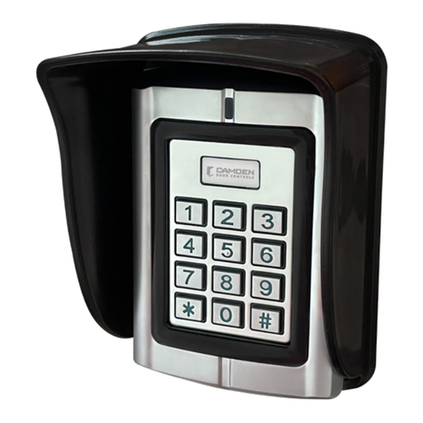
The CV-603PS-K1 is a kit that includes all the central
components for the MProxBLE controller. The CV-603
MProxBLE is a stand alone controller housed in a plastic
enclosure that can be DIN mounted.To congure the controller,
the CV-603 application is available on the Appstore for iPhone®
users and on the Google Play for Android® users.
2. SPECIFICATIONS
Power supply 12VDC
Average consumption < 100 mA
Receiver Frequency 433Mhz
Number of users 2000
Number of events 3000
Number of reader inputs 2
Types of reader input Wiegand 26, 30, 34, 37 bit
Number of relay outputs 2
Types of relay outputs Timed 1-180 seconds
Momentary, bi-stable/latch
Contact rating 30VDC @ 1 Amp
Operating Temperature -4°F to 131°F (-20°Cto +55°C)
DIN rail mount Yes
IP ratings IP 20
Weight 7 oz. (200 g)
Size of controller housing.
(For metal cabinet, refer to
last page.)
4-1/2" H x 3-1/2" W x 1-3/4" D
(115mm x 90mm x 44mm)
ID reading
STATE LED 2: RED
Denied ID
2 Flashes
Authorized
ID
On 1s
4. VISUAL INDICATOR LED ON MPROXBLE
CONTROLLER
Smartphone
connection
STATE LED 1: BLUE
Waiting for
smartphone
connection
Power
1 Flash every 5s
Smartphone
connected
Power
ON
3. PROGRAMMING
TheMProxBLE application is available on iPhone® (Appstore)
and Android® (Google Play).
Power
Power
CV-603 MProxBLE Controller /
CV-603PS-K1 MProxBLE Controller Cabinet Kit
INSTALLATION INSTRUCTIONS
CV-603-BLE CV-603PS-K1

Page 2 of 20
CV-603 MPROXBLE CONTROLLER / CV-603PS-K1 MPROXBLE CONTROLLER CABINET KIT
INSTALLATION INSTRUCTIONS
5. WIRING
Vin-
C1
NO1
NC1
C2
NO2
NC2
Vin+
I1
I2
I3
GND
T1
T2
Shield
5-16 VDC
Ground
Data 0
Data 1
Blue
Green
Red
Black
+12V
GND
RS485-
RS485+
12V
GND
DO0
DO1
BP1
GND
VAL1
GND
ANT
NC 1
COM1
NO 1
NC 2
COM2
NO 2
VAL2
GND
BP2
D11
D10
GND
12V
Alarm Annunciator
CV-603 Door Controller
Transformer
16VAC, 40 VA
Card Reader
AC to DC Power Supply
Door Posion Switch
Request to Exit PIR REX Detector
Door Strike 12 VDC
Wire Antenna
AC AC - +
TransformerDC Output
AC DC
12V 6V
BATT +
BATT -
Baery
Leads
(-ve)
(+ve)
Connect posive
wire to colored wire
represenng the
preferred color of
the dome light.
(+)
(-)
(Can be replaced with an Exit Switch)
=
Vin-
C1
NO1
NC1
C2
NO2
NC2
Vin+
I1
I2
I3
GND
T1
T2
Cathode mark
Diode
(Can be replaced with a MOV)
D1
Camden Model: CM-AF142SO
Camden Model: CM-RQE70 PIR Rex or CM-30E Exit Switch
Camden Model: CV-7400
Camden Model: CX-TRP-4016
Camden Model: CX-ED1079EL
Camden Model: 60-69B002
Doed line represents metal cabinet of CV-603PS-K1 version
SINGLE DOOR with Alarm annunciaon
SINGLE DOOR With ALARM ANNUNCIATOR

Page 3 of 20
CV-603 MPROXBLE CONTROLLER / CV-603PS-K1 MPROXBLE CONTROLLER CABINET KIT
INSTALLATION INSTRUCTIONS
Bill of material:
Camden Model# Camden Model#
Item Description Quantity CV-603PS-K1 CV-603
1 Controller 1 CV-603 provided in kit CV-603
2DC Power Supply 160-69B002 - provided in kit PS-13
3 Transformer 1 CX-TRP-4016 provided in kit CX-TRP-4016
4 Alarm Annunciator 1 CM-AF142SO CM-AF142SO
5 Door Strike, 12 VDC 1CX-ED1079 CX-ED1079
6Door Position Switch, a door latch monitor switch can be
used, add sux "L" to CX-ED1079 1CX-MDA surface or CX-MDH
recessed.
CX-MDA surface or CX-MDH
recessed.
7Proximity Card Reader, 125 KHz. Not required if
transmitters are used. 1CV-7400 CV-7400
8Request to Exit Device 1CM-RQE70 PIR sensor or
CM-30E Push button.
CM-RQE70 PIR sensor or CM-
30E Push button.
System Operation:
a) The door is normally locked and closed. The door position switch conrms when the door is closed.
b) A user presents a card credential in front of the card reader. The card reader’s red LED indicates it is powered. When the credential is
within 2 inches, the reader will beep, and the controller red LED will pulse on 1 second to conrm the credential data was received. If
the controller red LED blinks twice, the credential is being denied by the controller.
c) If the credential is approved by the controller, the door strike will energize for the pre-set period duration. The door strike will energize
for the full duration of the period until the door is opened and the door position changes state. As soon as the door is opened, the door
strike shall turn o securing the door as soon as it closes.
d) Users exiting the door, must be detected by the request to exit device; manually by a push switch or automatically using a PIR detector.
Opening the door without a request to exit switch shall cause the controller to generate a door forced open alarm.
e) An alarm annunciator shall be triggered for the following selected alarm conditions. Relay 2 must be congured for ALARM and Relay 1
conguration must have door contact ON to activate these alarm conditions.
a. Intrusion
b. Door not opened after an approved credential read.
c. Door not closed after access. Alerts managers when the door is being left open.
d. Anti-passback
e. Access denied by location – Attempts made by credentials not approved by either reader 1, channel 1, reader 2 or channel 2.
f. Access denied by schedule.
g. Unknown user – a credential not enrolled into the controller user data base.
f) Administrators shall use the app to control and congure the CV-603 controller using wireless Bluetooth. A steady on blue LED on the
controller will conrm the connection.

Page 4 of 20
CV-603 MPROXBLE CONTROLLER / CV-603PS-K1 MPROXBLE CONTROLLER CABINET KIT
INSTALLATION INSTRUCTIONS
Shield
5-16 VDC
Ground
Data 0
Data 1
+12V
GND
RS485-
RS485+
12V
GND
DO0
DO1
BP1
GND
VAL1
GND
ANT
NC 1
COM1
NO 1
NC 2
COM2
NO 2
VAL2
GND
BP2
D11
D10
GND
12V
Door Controller CV-603
Transformer
16VAC, 40 VA
Card Reader
AC to DC Power Supply
Wire Antenna
AC AC - +
TransformerDC Output
AC DC
12V 6V
BATT +
BATT -
Baery
Leads
=
Cathode mark
Diode
(Can be replaced with a MOV)
(+)
(-)
D1
(grey)
(orange)
Door Status
Sensor
Push to Exit
(+)
(-)
Door Status
Sensor
Data 1
Data 0
Ground
5-16 VDC
Shield
Push to Exit
Card Reader
D1
(grey)
(orange)
DC Door Ske
CX-ED1079DL
DC Door Ske
CX-ED1079DL
CX-TRP-4016
CM-30
CV-7400
CV-7400
CM-30
Two Door Access Configuration
Camden Model: 60-69B002
TWO DOORS: No Alarm Annunciator

Page 5 of 20
CV-603 MPROXBLE CONTROLLER / CV-603PS-K1 MPROXBLE CONTROLLER CABINET KIT
INSTALLATION INSTRUCTIONS
Bill of material:
Camden Model# Camden Model#
Item Description Quantity CV-603PS-K1 CV-603
1 Controller 1 CV-603 provided in kit CV-603
2 DC Power Supply 1 60-69B002 - provided in kit PS-13
3 Transformer 1 CX-TRP-4016 provided in kit CX-TRP-4016
4 Door Strike, 12 VDC 2 CX-ED1079 CX-ED1079
5
Door Position Switch, a door latch
monitor switch can be used, add
sux "L" to CX-ED1079
2 CX-MDA surface or CX-MDH recessed. CX-MDA surface or CX-MDH recessed.
6
Proximity Card Reader, 125 KHz.
Not required if transmitters are
used.
2 CV-7400 CV-7400
7Request to Exit Device 1CM-RQE70 PIR sensor or CM-30E Push
button.
CM-RQE70 PIR sensor or CM-30E Push
button.
System Operation:
a) The doors are normally locked and closed. The door position switch conrms when the doors are closed.
b) A user presents a card credential in front of the card reader. The card reader’s red LED indicates it is powered. When the credential is
within 2 inches, the reader will beep, and the controller red LED will pulse on 1 second to conrm the credential data was received. If the
controller red LED blinks twice, the credential is being denied by the controller.
c) If the credential is approved by the controller, the door strike will energize for the pre-set period duration. The door strike will energize
for the full duration of the period until the door is opened and the door position changes state. As soon as the door is opened, the door
strike shall turn o securing the door as soon as it closes.
d) Users exiting the door, must be detected by the request to exit device; manually by a push switch or automatically using a PIR detector.
Opening the door without a request to exit switch shall cause the controller to generate a door forced open alarm.
e) Administrators shall use the app to control and congure the CV-603 controller using wireless Bluetooth. A steady on blue LED on the
controller will conrm the connection.

Page 6 of 20
CV-603 MPROXBLE CONTROLLER / CV-603PS-K1 MPROXBLE CONTROLLER CABINET KIT
INSTALLATION INSTRUCTIONS
Vin-
C1
NO1
NC1
C2
NO2
NC2
Vin+
I1
I2
I3
GND
T1
T2
Request to Exit Detector
Relay 1
Relay 2
Data1
Data 0
Ground
5-16 VDC
Shield
+12V
GND
RS485-
RS485+
12V
GND
DO0
DO1
BP1
GND
VAL1
GND
ANT
NC 1
COM1
NO 1
NC 2
COM2
NO 2
VAL2
GND
BP2
D11
D10
GND
12V
Door Controller
CV-603
Transformer
16VAC, 40 VA
Card Reader
AC to DC
Power Supply
Door Strike 12 VDC
Wire Antenna
AC AC - +
TransformerDC Output
AC DC
12V 6V
BATT +
BATT - Baery
Leads
1
2
3
4
5
6
7
8
9
10
11
12
13
14
15
16
PWR
PWR
NO
COM
NC
NO
COM
NC
WET 1
DRY 1
WET 2
DRY 2
Door Operator
Door Relay
Vin-
C1
NO1
NC1
C2
NO2
NC2
Vin+
I1
I2
I3
GND
T1
T2
Blue
Green
Red
Black
Alarm Annunciator
CM-AF142SO
Connect the
colored wire for
the desired light
color.
CX-TRP-4016
CX-12PLUS
CM-RQE70
CV-7400
Application: 1R1DS-1A-1PIRREX-1DO
CX-ED1079DL
SINGLE DOOR Frictionless Access Control Solution

Page 7 of 20
CV-603 MPROXBLE CONTROLLER / CV-603PS-K1 MPROXBLE CONTROLLER CABINET KIT
INSTALLATION INSTRUCTIONS
Bill of material:
Camden Model# Camden Model#
Item Description Quantity CV-603PS-K1 CV-603
1 Controller 1 CV-603 provided in kit CV-603
2DC Power Supply 160-69B002 - provided in kit PS-13
3 Transformer 1 CX-TRP-4016 provided in kit CX-TRP-4016
4Door Strike, 12 VDC 1CX-ED1079 CX-ED1079
5 Door Relay 1 CX-12PLUS CX-12PLUS
6
Door Position Switch, a door latch
monitor switch can be used, add
sux "L" to CX-ED1079
1CX-MDA surface or CX-MDH recessed. CX-MDA surface or CX-MDH re-
cessed.
7
Proximity Card Reader, 125 KHz.
Not required if transmitters are
used.
1CV-7400 CV-7400
8Request to Exit Device 1CM-RQE70 PIR sensor or CM-30E Push
button.
CM-RQE70 PIR sensor or CM-30E
Push button.
9Alarm Annunciator 1 CM-AF142SO CM-AF142SO
System Operation:
a) The system operation is identical to the single door operation (a) and (b).
b) If the credential is approved by the controller, the door strike will energize for the pre-set period duration on the Cx-12 PLUS module.
The door operator will trigger to operate after the door strike has been energized. Once the pre-set periods have expired, the door ope-
rator and strike shall de-energize from the Cx-12PLUS module.
c) Users exiting the door, must be detected by the request to exit device; manually by a push switch or auto matically using a PIR detector.
Opening the door without a request to exit switch shall cause the controller to generate a door forced open alarm
d) An alarm annunciator shall be triggered for the following selected alarm conditions. Relay 2 must be cong ured for ALARM and Relay 1
conguration must have door contact ON to activate these alarm conditions.
a. Intrusion
b. Door not opened after an approved credential read.
c. Door not closed after access. Alerts managers when the door is being left open.
d. Anti-passback
e. Access denied by location – Attempts made by credentials not approved by either reader 1, channel 1, reader 2 or channel 2.
f. Access denied by schedule.
g. Unknown user – a credential not enrolled into the controller user data base.
e) Administrators shall use the app to control and congure the CV-603 controller using wireless Bluetooth. A steady on blue LED on the
CV-603 controller will conrm the connection.

Page 8 of 20
CV-603 MPROXBLE CONTROLLER / CV-603PS-K1 MPROXBLE CONTROLLER CABINET KIT
INSTALLATION INSTRUCTIONS
+
-
Gate
Operator
Card
Reader
Loop
Detector
Loop
Detector
Card
Reader
Gate
Operator
Power Supply,
12 VDC
GATE 1
GATE 2
TWO VEHICLE GATES: ANTI-PASSBACK
Antenna
12 V
GND
Data 0
Data 1
Data 1
Data 0
GND
12 V
Automac
Exit
Detector
Automac
Exit
Detector
TWO VEHICLE GATES: ANTI-PASSBACK

Page 9 of 20
CV-603 MPROXBLE CONTROLLER / CV-603PS-K1 MPROXBLE CONTROLLER CABINET KIT
INSTALLATION INSTRUCTIONS
Bill of material:
Item Description Quantity Camden Model #
1 MproxBLE Controller 1 CV-603
212 VDC Power supply, usually accessible from gate controller. 1
3 Gate Operator 2
4 Loop or beam detector 2
5Automatic exit switch or sensor 2
6Proximity Card Reader, 125 KHz 2CV-7400
7 Request to Exit device 2
System Operation:
a) The gates are normally closed.
b) A vehicle approaches and stops in front of gate. A sensor or loop detector will validate the position of the vehicle and enable both the
card reader and receiver. If the device wired to the VAL1 or VAL2 terminals do not detect the proper position of the vehicle, the reader
and receiver will prevent the user to trigger the gate to open.
c) Identical system operation for single door application (b).
d) If an automatic exit sensor is connected to the controller, vehicles exiting will be detected by the exit device triggering the gate to open.
e) Administrators shall use the app to control and congure the CV-603 controller using wireless Bluetooth. A steady on blue LED on the
CV-603 controller will conrm the connection.

Page 10 of 20
CV-603 MPROXBLE CONTROLLER / CV-603PS-K1 MPROXBLE CONTROLLER CABINET KIT
INSTALLATION INSTRUCTIONS
MProxBLE ASSEMBLY AND
DINRAIL ASSEMBLY
1. Take the top of the
MProxBLE base and hook it
onto the top of the DIN rail.
Then take the bottom part with
the red clip and push it onto
the rail until it snaps into place.
2. Slide the component along
the rail to desired location/
spacing from component A.
Power Supply ASSEMBLY
1. Take the Snap track, align
the 2 square holes with
the mounting holes on the
cabine base.
2. Take the 2 screws and
place them through the
holes from the back of the
cabinet. Place the washer
over the snaptrack and over
the screws. Screw the nuts
onto the screw, securing the
snaptrack is in place.
3. Push the power supply
onto the top of the
snaptrack, into the grooves
allowing the snaptrack to
hook onto the power supply.
6. CV-603PS-K1 CABINET ASSEMBL
Power supply ASSEMBLY
1. Take the Snap track, align the 2 square holes
with the mounting holes on the cabine base.
2. Take the 2 screws and place them through the
holes from the back of the cabinet. Place the washer
over the snaptrack and over the screws. Screw the
nuts onto the screw, securing the snaptrack is in
place.
3. Push the power supply onto the top of the
snaptrack, into the grooves allowing the snaptrack to
hook onto the power supply.
BLE Base and Dinrail ASSEMBLY
1. Take the bottom of the BLE base
and hook it onto the bottom of the DIN
rail. Then take the top part with the red
clip and push it onto the rail until it snaps
into place.
2.
to desired location/spacing from
Component A
Snaptrack
Power Supply
BLE Base
DIN Rail
Battery
Optional 12 volt, 4AH battery
provided by others.
Controller

Page 11 of 20
CV-603 MPROXBLE CONTROLLER / CV-603PS-K1 MPROXBLE CONTROLLER CABINET KIT
INSTALLATION INSTRUCTIONS
41
8''
[105mm]
23
4''
[70mm]
1
4''
[5mm]
Drill 1/4'' for screw
4 places
7. CV-603 BLE TEMPLATE


Page 13 of 20
CV-603 MPROXBLE CONTROLLER / CV-603PS-K1 MPROXBLE CONTROLLER CABINET KIT
INSTALLATION INSTRUCTIONS
8. SAFETY WARNINGS
These warnings are an integral and essential part of the product,
and must be delivered to the user. Read them carefully: they provide
important installation, operating, and maintenance instructions. Keep
this form and give it to any persons who may use the system in the
future. Incorrect installation or improper use of the product may cause
serious danger.
9. INSTALLATION INSTRUCTIONS
• Installation must be performed by a qualied professional and
must observe all local, state, national and European regulations.
• Before starting installation, make sure that the product is in perfect
condition.
• Laying, electrical connections, and adjustments must be done to
“Industry Standards”. The product must be installed in a box not
accessible to the operator.
• Do not install the product in an explosive environment or in an area
disturbed by electromagnetic elds.
• The presence of gas or inammable fumes is a serious safety
hazard.
• Provide an overvoltage protection, mains/knife switch and/or
dierential on the power network that is suitable for the product
and conforming to current standards. The manufacturer declines
any and all liability if any incompatible devices and/or components
are installed that compromise the integrity, safety, and operation of
the product.
• Only original spares must be used for repair or replacement of
parts. The installer must supply all information regarding the
operation, maintenance, and use of individual components and of
the system as a whole
10. MAINTENANCE
To guarantee the eciency of the product, it is essential that qualied
professionals perform maintenance at the times and intervals required
by the installer, by the manufacturer, and by current law. All installation,
maintenance, repair and cleaning operations must be documented.
The user must store all such documentation and make it available to
competent personnel.
FCC: This device complies with part 15 of the FCC Rules. Operation is
subject to the following two conditions: (1) This device may not cause
harmful interference, and (2) this device must accept any interference
received, including interference that may cause undesired operation.
This equipment has been tested and found to comply with the limits
for a Class B digital device, pursuant to part 15 of the FCC Rules. These
limits are designed to provide reasonable protection against harmful
interference in a residential installation. This equipment generates, uses
and can radiate radio frequency energy and, if not installed and used
in accordance with the instructions, may cause harmful interference to
radio communications. However, there is no guarantee that interference
will not occur in a particular installation. If this equipment does cause
harmful interference to radio or television reception, which can be
determined by turning the equipment o and on, the user is encouraged
to try to correct the interference by one or more of the following
measures:
• Reorient or relocate the receiving antenna.
• Increase the separation between the equipment and receiver.
• Connect the equipment into an outlet on a circuit dierent from
that to which the receiver is connected.
• Consult the dealer or an experienced radio/TV technician for help.
Changes or modications made to this equipment not expressly
approved by Camden Door Control could void the user’s authority to
operate the equipment.
TERMS AND LIMITS OF WARRANTY
Refer to Camden’s warranty online for details.
https://www.camdencontrols.com/about/product_warranty

Page 14 of 20
CV-603 MPROXBLE CONTROLLER / CV-603PS-K1 MPROXBLE CONTROLLER CABINET KIT
INSTALLATION INSTRUCTIONS
CV-603 Quick Start up Guide for User App
1. REQUIREMENTS:
1. CV-603 Controller
2. Smartphone with Bluetooth 5
3. The CV-603 app. (Supports both iOS and Android 5.0 and later).
4. Credentials; a proximity card, a key tag or 2 button transmitter,
either or both.
5. Card Reader optional if no transmitters are used
11 STEPS TO GET THE MPROXBLE CONTROLLER
CONFIGURED.
1. Download and install the app from Google Play or
the App Store.
a. Allow the app to access your internal storage.
b. Bluetooth must be enabled on your phone and you
must be within range of the MProxBLE controller for the
app to respond. (under 60 feet, (20 m) is recommended.)
Logo used for app
2. Open the app and click
on UPDATE LIST icon.
a. A default name for your
controller will appear. The
title will state uninitialized.
3. Tap on the default
name and the home page
will appear.
a. Conrm you are
connected to the controller
by the ‘connection to the
central: (name)’ message.
b. The default login and
password will appear
(ADMIN).
4. Click on the CONNECT icon to connect to the
controller.
a. A progress line will scroll from left to right of the screen
during this process.
b. The General
Conguration screen
will appear after
connecting.
c. It is recommended
to replace the default
equipment name that
will be relatable to you.
Example: 260 Main
Street, Utility closet B2,
etc.
NOTE: If the process line stops at the beginning, close
the app and re-open the app to update list before
attempting to connect again.
User friendly Bluetooth app provides quick and easy set-up and management for
property and security managers.

CV-603 MPROXBLE CONTROLLER / CV-603PS-K1 MPROXBLE CONTROLLER CABINET KIT
INSTALLATION INSTRUCTIONS INSTALLATION INSTRUCTIONS
5. Adjust the 5 slide switches for the requirements
of your site.
Default recommendations have been selected to expedite the
process.
a. Anti-passback: Leave o if you do not intend to restrict
users from sharing their card credentials with other people
to gain entry.
b. Only encrypted remote controls: Turn on to get the
best performance of 2 button transmitters, if used.
c. Summer/Winter Europe or Summer/Winter USA/
Canada: Turn on only if your area is using daylight savings
time.
d. Facility code Management: Turn on if you will be
monitoring regularly the event reports.
i. If you turn on this feature, you must enter a value
for the facility code that is being used on your card
credentials. (1 to 255 if using 26-bit Wiegand cards.)
6. Scheduling:
A pop up message will appear, “Do you want to congure a
schedule now?” Click Yes to proceed to the Time table
a. You can rename the default name ‘STANDARD’ to M-F
as an example or something relatable to your facility
conguration.
b. Click on the ALL label underlined in red to select one
of the three views; ALL, Monday to Sunday or Monday to
Friday/Weekend.
c. Click on the time to alter the time slots T1 to T4 per
period.
d. To save your settings,
click on VALIDATE icon
at the bottom. (Android
app). Click on DONE icon
(iOS app).
On iOS Devices
Tap the time you wish to adjust and the time will appear on
the bottom of the screen. Scroll the hours and minutes for the
time preferred. To save the new values, tap on the DONE icon.
7. Relay Conguration:
There are three standard modes for the relays;
(i) Momentary, 2 seconds on then o
(ii) Timed, a period dened in hours, minutes, and
seconds.
(iii) Bistable or latched, the relay toggles on or o.
Depending on the type of mode, secondary selections
will appear.
Page 15 of 20

Page 16 of 20
CV-603 MPROXBLE CONTROLLER / CV-603PS-K1 MPROXBLE CONTROLLER CABINET KIT
INSTALLATION INSTRUCTIONS
Momentary Timed Bistable or
latching
Alarm
ONLY Available
for Relay 2
Description
Conditional
Input ON or OFF ON or OFF Not Available Not Available
This selection will prevent the respective
relay to activate unless the controller
validation terminals VAL1 or VAL2 are
normally closed while a credential is being
presented. To prevent vehicle tailgating this
feature is turned on.
Door
Contact ON or OFF
ON or OFF
{If ALARM features
including intrusion,
door not opened or
door ajar are to be
activated, this must
be on.}
Not Available Not Available
This will monitor the validation terminals
VAL1 and VAL2 wired to a normally closed,
door position switch. When active, the
relay energized period will immediately
turn o as soon as the door is opened
to immediately relock the door as soon
as it closes. Use this feature to prevent
unauthorized entry by individuals
reopening the door during the door release
period.
Schedule
reading ID
Select
one of the
predened
schedules.
Select one of
the predened
schedules.
Select one of
the predened
schedules.
Not Available
Select the schedule you wish for the selected
mode to function. The default schedules;
NEVER and ALWAYS will be available. If you
added more schedules, you can select the
schedule previously dened.
Lock and
unlock
Schedule
Select
one of the
predened
schedules.
Select one of
the predened
schedules.
Select one of
the predened
schedules.
Not Available The relay will automatically activate to the
schedule selected.
First Person
In Delay ON or OFF ON or OFF ON or OFF Not Available
The relay will not automatically activate
(open) until an authorized credential
is used. This is to prevent a relay to be
energized unless an employee has entered
the facility. Schedule forced opening must
not be set to NEVER for this to appear.
Unlock Time Not Available In 00h: 00m: 00s: Not Available Not Available Enter the time in hours, minutes, and
seconds.
Door Ajar
Limit Not Available In 00h: 00m: 00s: Not Available In 00h: 00m: 00s:
This feature is ideal for limiting the time
the door can remain open to prevent
unauthorized entry. The eld appears only
when the Door Contact is switched on.
Alarm
Shut-O
Period
Not Available Not Available Not Available In 00h: 00m: 00s:
Enter the maximum time in hours, minutes
and seconds before the relay automatically
de-energizes.
On Relay 2 ONLY
For applications requiring a common alarm annunciation, relay 2 can be wired to an audible-visual device to alert security
personnel to an alarm condition.
Click on Relay 2 mode eld, to pop open relay operating mode choices. You will notice ‘Alarm’ as an additional selection. Click on
‘Alarm’ to open alarm selections below.
FEATURE RESTRICTIONS AND LIMITATIONS

Page 17 of 20
CV-603 MPROXBLE CONTROLLER / CV-603PS-K1 MPROXBLE CONTROLLER CABINET KIT
INSTALLATION INSTRUCTIONS
ALARM Conditions Requirements Description
Alarm, Intrusion Relay 1 Door Contact must be ON If the door is opened without a valid credential,
an alarm condition will occur.
Alarm, door not open Relay 1 Door Contact must be ON If the door is not opened after a valid
credential, an alarm condition will occur.
Alarm, door not closed Relay 1 Door Contact must be ON If the door is left open past the relay unlock
time, an alarm condition will occur.
Alarm, user anti-pass back ON or OFF If a user violates the anti-pass back condition,
an alarm condition will occur.
Alarm, access denied by location ON or OFF If a credential is used on unapproved reader,
an alarm condition will occur.
Alarm, access denied by time schedule ON or OFF If a credential is used outside the time period
selected, an alarm condition will occur.
Alarm, access denied by date schedule ON or OFF If a credential is used outside the dates
selected, an alarm condition will occur.
Alarm, Unknown User ON or OFF If an unknown credential is used, an alarm
condition will occur.
Once you have made the selections, click on the VALIDATE icon. A pop-up alert message will appear to conrm your settings have been
saved. Click ok to close.
Alarm Output: RELAY2 is used for common alarm notications when selected. RELAY 1 must be set to ‘TIMED’ mode.
9. Group Conguration:
Every user must be assigned to a group. You can select to
turn any group on or o from this screen.
a. [Name] You can change the default group STANDARD
or add a new name up to 17 characters.
b. [Type] Tap on the default setting Badge/Transmitter
and a pop-up selection will appear. Select the type of
credential that will be accepted for this group.
i. Badge = Only cards or tags that are read inches
away from a proximity card reader wired to the
controller Reader 1 or Reader 2 terminals.
ii. Transmitter = Only battery powered, two button
transmitters that can be read over 100 feet from the
MProxBLE Controller.
iii. Badge/Transmitter = Both types of credentials will
be accepted.
c. [Schedule] Tap on the eld right of the label to see one
of the three default schedules for the group. Additional
schedules can be added from the main menu selection
under schedules.
i. Always – The group will always be active.
ii. Never – The group will never be active
iii. Standard – The active time and dates are dened
in schedules.

Page 18 of 20
CV-603 MPROXBLE CONTROLLER / CV-603PS-K1 MPROXBLE CONTROLLER CABINET KIT
INSTALLATION INSTRUCTIONS
d. [Relay 1 and Relay 2] Tap on the greyed out
numbered letters B and/or C to open the list of actions
that can trigger the relay.
i. C represents the channel; Channel 1 to 4 refers
to a transmitter’s button 1 to 4. Pressing the
corresponding button for the active ON channel
will trigger the relay. In most cases, only 2 buttons
are used
ii. B represents the badge; Selecting Reader 1
and/or Reader 2 to determine which reader(s) can
trigger the relay for the presented badge/card
credential.
e. [Bypass Conditional entry] Turning on this feature by
sliding the icon to the right will turn o the monitoring
of the VAL terminals.
f. [Bypass Anti-pass back] Turning on this feature will
ignore the pass back state of the user.
Once you have made the selections, click on the VALIDATE
icon. A pop-up alert message will appear to conrm your
settings have been saved. Click ok to close.
10. User Management:
This will bring you to the User Management screen where you
can add, search, and reset the anti-pass back state.
All references to credentials could be either a two button
transmitter or a proximity card/tag.
Transmitter versus proximity credentials:
Two button transmitter – The button #1 and #2 are
preassigned to RELAY1 and RELAY2 for entry and exit.
Proximity credentials – You can use RELAY1 for access
control and RELAY2 for alarm.
a. ADD USER: Click on ADD USER icon to open the screen to
add user credentials. You can manually enter each Wiegand
card number manually or auto-enroll the ID number using
the ID READ icon.
NOTE: It is recommended that you use card credentials
with the same facility code number you entered on
Central Setting page. If you use cards that have a
dierent facility code, you will be denied access due to
a mismatch of facility codes. All credentials provided
by Camden Controls will have identical facility codes to
ensure ease of use.
i. BULK ADD: To bulk add a sequence of credentials,
simply enter the start ID number into the User ID eld.
ii. Users Number: Enter the number of credentials to
be added or click on the + icon to increase the number
of credentials to be added.
Click on ADD icon to complete. A conrmation pop
up message will state “The user has been successfully
added”. Press OK to close.
b. SEARCH BY ID: To add the family and users name to
the bulk credentials you added, click on the Search by ID,
enter the rst ID number you entered then click on the
search icon. The User page for the assign ID will appear for
you to complete the entry by adding the family and users
name. When the name elds have been edited, click on
the Validate icon to save it. Repeat this sequence for the
remaining ID numbers that require the name elds to be
lled.
i. To add only one card, simply enter the card ID
number into the Users ID eld or
ii. press ID READ icon to auto enroll the card ID
by presenting the card in front of the card reader.
Pressing the ID Read icon shall activate the unit to
read the credential presented to the card reader to
automatically place the credential code it read into the
User ID eld.
NOTE: The Reset Anti-pass back icon only appears if anti-pass
back is selected on Central Settings from the main menu.

Call: 1.877.226.3369 / 905.366.3377
Visit: www.camdencontrols.com
Opening New Doors to
Innovation, Quality and Support!
CV-603PS-K1 MPROXBLE
INSTALLATION INSTRUCTIONS
File: CV-603-BLE&CV-603PS-K1_
Installation&QuickSetUpApp_Manual.indd
Rev. May 3rdth 2021
Part No.: 40-82B262
Simply enter the remaining data elds for family
name, username, users group.
iii. Press ADD icon to add it to memory.
c. A conrmation pop up message ‘The user has been
successfully added’ will appear. Press OK to close
Adding Transmitters:
Follow the same procedure above for adding one or
many transmitters but press one of the push buttons to
transmit the ID code to the controller.
11. Administrator Levels:
Select Session Management from the main menu to dene
the 5 administrative levels. If you have numerous managers
responsible for administrating this controller, you may wish to
restrict specic capabilities to protect the original conguration
or unclutter the screen to tasks the user is responsible for.
a. User: You can
change the default
entry of USER_1 by
simply overwriting the
eld.
b. Password: You can
change the default
entry of USER_1 by
simply overwriting the
eld.
c. User Management: Enables the person to; add user IDs,
search by ID, search by family name and reset the anti-pass
back.
d. Backup: Enables
the person to export or
import data.
e. History: Enables the
person to see past events
by pressing the EVENTS
icon.
f. Relay Commands:
Enables the user to see
the status of the validation
inputs (VAL1/VAL2), the
request to exit input
(BP1/BP2) and Alarm
status. They can manually
activate Relay 1 and Relay
g. Schedule: The person can alter schedules, holidays and
special days.
h. User Group Settings: The person can alter the group
settings.
For site managers, they may only need the rst three
selections turned on; User management, Backup and
History to perform their daily tasks.
To manually reset alarms, relay commands will need to
be selected.
ANTI-PASS BACK FEATURE: MProxBLE uses hard anti-pass
back. Users will be restricted from passing their credential,
‘pass back’, to another person to gain entry because once
they have entered, the system knows that they are inside and
won’t let them re-enter unless they rst exit. Hard anti-pass
back maintains a high level of security but may inconvenience
users who forget to use their card to enter or exit (by
following someone else in). The system will have their status
confused in the system if they do not badge in AND out, it will
think that they are outside when they are inside, and so will
not let them leave. Administrators can ‘reset’ the state of anti-
pass back using the MProxBLE app.
Reader 1 is designated as ‘entry’ and Reader 2 is designated
as ‘exiting’ under User Management anti-pass back eld.
When you create a badge: its Anti-pass back status is
«unknown» : it can be accepted indiscriminately the rst time
on an incoming or outgoing reader. As soon as it is accepted
on a reader it loses its “unknown” state and enters the cycle of
anti-pass back.
When the badge is accepted on an “entering” reader (reader 1),
its state of Antipass-back is “exiting”, means that it can only be
accepted on an “exiting” reader
When the badge is accepted on an “exiting” reader (reader 2),
its state Anti-passback is “entering” state means that it can only
be accepted on an “entering” reader
When powering up the MProxBLE, all users systematically
switch to an "unknown" state of anti-passback.
Feature Table
Anti-
Passback Alarm One Door Two
Doors
Request
to Exit
Anti-
Passback Yes Yes Yes Yes
Alarm Yes Yes No Yes
One
Door Yes Yes Not
Applicable Yes
Two
Doors Yes No Not
Applicable Yes
Request
to Exit Yes Yes Yes Yes
Page 19 of 20
NOTE: If you forget your password, you will need to do a
factory reset deleting all previous settings and user IDs.

6" [152.7mm]
95
8" [243.9mm]
77
8" [200.2mm]
111
8" [281.4mm]
CV-603 MPROXBLE CONTROLLER / CV-603PS-K1 MPROXBLE CONTROLLER CABINET KIT
INSTALLATION INSTRUCTIONS
This manual suits for next models
1
Table of contents
Other CAMDEN Controllers manuals