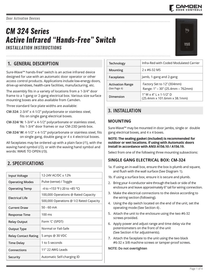
CM-324 Active Infrared “Hands-Free” Switch Installation Instructions
2-GANG (or 4x4) ELECTRICAL BOX: CM-324W
1a – If using an in-wall box ensure the box is plumb and
square, and ush with the wall surface. (See Diagram 1)
1b – If using a surface box, ensure it is secure & plumb.
1c – If using a 4 x 4 box, ensure the box is plumb and
square, and ush with the wall surface, then attach the
metal adaptor plate (included in the CM-324W package)
to the box using appropriate fasteners.
2 – Bring your 4-conductor wire through the back or side
of the enclosure and leave approximately 6” tail for wiring
connection.
3 – Make the electrical connections to the device
according to the wiring section (following).
4 – Using the dip switch located on the end of the unit,
set the operating mode. (See Section 4)
5 – Attach the unit to the enclosure using the two #6-32
screws provided.
6 – Apply power and adjust range and time delay via the
potentiometers on the front of the unit. (See Section 4 for
adjustments)
7 – Attach the faceplate to the unit using the two black
#6-32 x 3/8 machine screws or tamperproof screws.
Do not overtighten!!
DOOR FRAME: CM-324N
1a – If mounting directly in a 1¾” wide aluminum jamb,
make a cutout in the door frame at the intended location
as per Diagram 2. (See Diagram 2 on page 4)
Drill and tap two mounting holes as shown.
1b – If mounting the unit in our CM-23d deep jamb box,
rst mount the jamb box according to the instructions
packaged with the enclosure. Using the CM-23D as a
guide, drill a wire access hole through the jamb to sh the
wiring through.
2 – Bring your 4-conductor wire through the back or side
of the enclosure (or Jamb) and leave approximately 6” tail
for wiring connection.
3 – Make the electrical connections to the device
according to the wiring section (following).
4 – Using the dip switch located on the end of the unit, set
the operating mode. (See Section 4)
5 – Attach the unit to the enclosure or jamb using the two
#6-32 screws provided.
6 – Apply power and adjust range and time delay via the
potentiometers on the front of the unit. (See Section 4 for
adjustments)
7 – Attach the faceplate to the unit using the two black
#6-32 x 3/8 machine screws or tamperproof screws.
Do not overtighten!!
Wiring
CAUTION: Do not apply power to the unit until all second-
ary wiring is complete, and dip-switches have
been set.
The CM-324 can be powered from 12 or 24 volts, AC or
DC. Connect the two Red wires, (which are non-polarity
sensitive) to the power source.
The output is a form C relay. N.O is Blue, N.C. is Violet,
and Common is Green. Selecting the correct output is also
dependant on the operating mode chosen. (See Section
4) Most applications will utilize the N.O. and Common
terminals.
Section 3:
Applications & Set-up Applications
See Diagram 3 for the location of the Dip switches.
Switch 1 – Normal Mode/Fail-Safe Mode
Choose Normal Mode if you wish the N.O. contact to remain
open if the power were to fail. This is the factory setting.
Choose Fail-safe Mode if you wish the contacts to close
upon power fail. Move the Dip switch to OFF position, and
wire your device to the Common and N.C. wires.
Switch 2 – Time Delay Mode/Toggle Mode
Factory setting is Time Delay (Sense) mode, whereby the
contact closure will be adjustable from 1 – 5 seconds
using the Time Delay Potentiometer.
In Toggle (or Switch) mode, when the CM-324 is activated
once, the relay will stay energized until it is activated once
again. (The adjustable timer is inactive in this mode)
Photo Eye
Red LED
Time Delay
Adjustment
Dip Switch
Red
Red
Blue
Green
Violet
12-24V
Power
N.O.
COM
N.C.
Range
Adjustment Wiring Pigtail
CM-324
Diagram 3 - Location of Adjustments
Page 2 to 4
