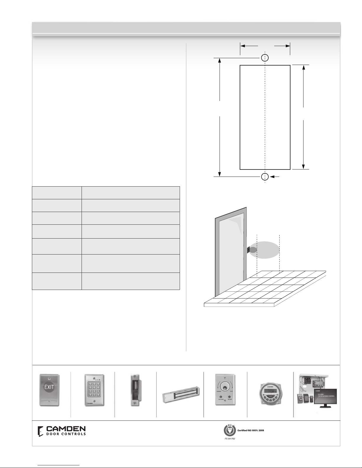
CM-330 Battery Operated Active Infra-red “Hands-Free” Switches Installation Instructions
2- GANG (or 4x4) ELECTRICAL BOX: CM-330W
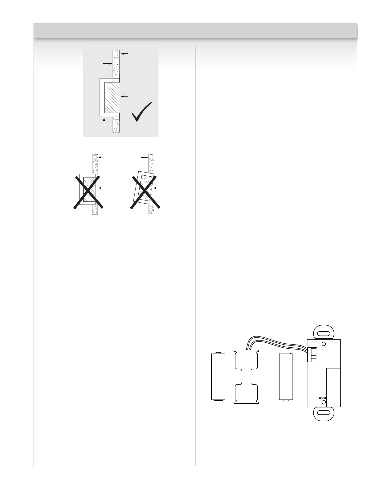
1a – If using an in-wall box ensure the box is plumb and
square, and ush with the wall surface. (See Diagram 1)
1b – If using a surface box, ensure it is secure & plumb.
1c – If using a 4 x 4 box, ensure the box is plumb and
square, and ush with the wall surface, then attach
the metal adaptor plate (included in the CM-330W
package) to the box using appropriate fasteners.
2 – Attach the unit to the enclosure using the two #6-32
screws provided.
3 – Attach the faceplate to the unit using the two black
#6-32 x 3/8 machine screws or tamperproof screws.
Do not overtighten!!
DOOR FRAME: CM-324N
1a – If mounting directly in a 1¾” wide aluminum jamb,
make a cutout in the door frame at the intended location
as per Diagram 3. (See Diagram 3 on page 3)
Drill and tap two mounting holes as shown.
1b – If mounting the unit in our CM-23D deep jamb box,
rst mount the jamb box according to the instructions
packaged with the enclosure. Using the CM-23D as a
guide, drill a wire access hole through the jamb to sh
the wiring through.
2 – Using the dip switch located on the end of the unit,
set the operating mode. (See Section 4)
3 – Attach the unit to the enclosure or jamb using the
two #6-32 screws provided.
4 – Attach the faceplate to the unit using the two black
#6-32 x 3/8 machine screws or tamperproof screws.
Do not overtighten!!
Pairing the CM-330
CM-330 battery operated wireless SureWave™ utilizes
our Lazerpoint RF technology and is for use with Camden
CM-RX91 or CM-RX92 Lazerpoint receivers.
To pair the CM-330 transmitter to a receiver, press the
PB1 (or PB2) button on the Receiver using a small blunt
object such as a small blade screwdriver or similar. Within
10 seconds, wave your hand in front of the CM-330 to
activate it. The Green LED Array on the receiver will ash
once to conrm enrollment. Repeat with any additional
CM-330 wireless Sure-wave™ switches. Activating the
paired CM-330 again will signal the receiver that you are
nished programming and LED’s 1 & 2 will ash, in an
alternating sequence. Activating the CM-330 a third time
will activate the receiver’s relay and corresponding LED,
and also the device connected to the relay contacts.
If you wait longer than the 10 second period, the receiver
will time out of Pairing Mode and revert back to standby.
The LED will then ash to indicate the number of
transmitters learned into the receiver.
Wiring
CAUTION: Do not apply power to the unit until all wiring is
complete, and dip-switches have been set.
The CM-330 is powered from 2 AA batteries (supplied). The
battery holder has been pre-installed. Insert the batteries
into the battery holder. Please be careful that the polarity
of the batteries is correct.
Diagram 1 - Proper Box Installation
Rough Wall
Finish
Recessed
Box
Unaligned
Box
Wall
Wall Box
Flush
Smooth
Wall Finish
CAMDEN
Request To
Exit Input
Power In -
Power In +
Diagram 2
Page 2 of 4