CAMION ICE MASTER T Series User manual

Version 1.4 Copyright © Enduraplas. All Rights Reserved.
Product Codes:
IMS250T160, IMS250T160E, IMS300T160, IMS300T160E,
IMS500T160, IMS500T160E, IMS500T160SS, IMS800T160,
IMS800T160E, IMS800T160SS, IMS1200T160, IMS1200T160E,
IMS1200T160SS, IMS1600T160, IMS1600T160E, IMS1600T160SS,
IMS1900T160, IMS2500T160, IMS2500T160E, IMS2500T160SS,
IMS3000T160, IMS3000T160E, IMS3000T160SS
OWNER’S MANUAL
ICE MASTER T-SERIES
®

3Version 1.4
English
2Ice Master®T-Series
English
CONTENTS INTRODUCTION
Congratulations! You now own an Camion™ sprayer.
Durable design and construction assure you a lifetime of
extreme performance. No sprayer is tougher. No sprayer will
last longer.
Take a look through this owner’s manual to learn how the
pros use their Camion™ sprayer.
INTRODUCTION 3
WARNINGS 4 & 5
GETTING STARTED 6 - 17
CALIBRATING 18 & 19
MAINTAINING 20 & 21
TROUBLESHOOTING 22 & 23
WARRANTY 24 - 27
PARTS BREAKDOWNS - ICE MASTER®
T-SERIES 28 - 47
!
Discover More Helpful Tips:
www.IceControlTraining.com
Watch Instruction Videos:
www.youtube.com

5Version 1.4
English
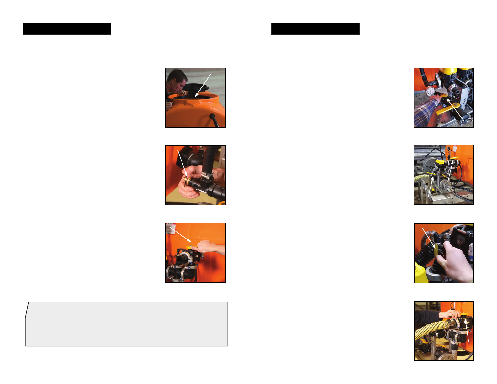
4Ice Master®T-Series
English
WARNINGS
1. Do not exceed vehicle manufacturers loading, towing or
lifting specications and regulations.
2. Ensure tank is rmly secured in an appropriate manner.
3. Use caution at all times, particularly when driving on
rough terrain.
4. Comply with chemical manufacturers safety requirements
and all relevant legislations.
5. ALWAYS keep tank tightly covered, to prevent children or
animals from entering tank.
6. Tank is not re resistant. NEVER expose it to open ame
or heat.
7. Keep sharp objects from tank. Tank could be punctured
and contents could escape and cause injury to persons
or property.
8. This tank can be used only with polyethylene compatible
liquids. If you are uncertain, ask chemical supplier if
material can safely be stored in a polyethylene tank.
USE OF TANK WITH ANY OTHER MATERIAL COULD
CAUSE TANK TO FAIL, RESULTING IN INJURY OR
PROPERTY DAMAGE.
9. DO NOT MIX CHEMICALS. THIS CAN RESULT IN
DAMAGE TO THE TANK OR NEARBY PERSONS OR
PROPERTY.
10.Clean out tank before changing chemicals OTHERWISE
A DANGEROUS MIXTURE OF CHEMICALS
COULD CAUSE DAMAGE TO PERSONS, TANK OR
PROPERTY.
11. Regular service and maintenance is the Owner’s
responsibility and is a condition of your warranty.
12.FAILURE TO COMPLY WITH ALL WARNINGS
AND INSTALLATION INSTRUCTIONS WILL VOID
WARRANTY.
!
Discover More Helpful Tips:
www.IceControlTraining.com
Calcium Chloride Brine, Salt Brine and Premium Branded
Liquids.
Caution: Brine that contain tacky substances or solid
particles may clog pumps and nozzles. These are not
recommended.
Warning: DO NOT USE any products that contain
petroleum or petroleum by-products of any kind. These
destroy seals and will void warranty.
COMPATIBLE LIQUIDS
!
!
13.No modications and/or alterations may be made to this
sprayer. Any such modications not only void the sprayer
warranty but can make the unit dangerous to anyone
operating the pump.
14.Always inspect hoses and piping to avoid burst injuries.
15.DO NOT turn suction valve o while pump is running.
NEVER RUN PUMP DRY.

7Version 1.4
English
6Ice Master®T-Series
English
1) If you ordered the hose reel option,
screw the hose reel handle into place.
Setting-up the Sprayer
GETTING STARTED GETTING STARTED
5) Next you will need to connect the
solenoid controller. Make sure to
connect the matching left, right, center
cables to the corresponding plugs as
shown in the image.
6) If you ordered a light with your unit,
plug it into the wire harness. If you did
not order a light, then disregard the light
plug.
3) If you wish to mount a boom, add
the bolts and plastic washers to the two
boom brackets.
4) Connect the brackets to the frame
and loosely secure them in order to
mount your boom.
Setting-up the Sprayer
2) If you purchased a hitch mount boom
for your Ice Master®T-Series unit, you
may hook this up to the hitch on your
pickup.
7) Run the power cable up to your cab
and connect it to your controller.
8) Then connect the controller to the
power outlet in your cab.

8 9Version 1.4 Version 1.4
English English
Installing the Sprayer
GETTING STARTED
2) When loading your sprayer, we
recommend placing a block of wood
between your sprayer and the front of
the bed of your truck.
3) On the Ice Master® E-Series, there
are tie-down points on the side of the
frame that allow you to strap the unit
down.
1) The two openings at the front of the
frame allow you to move the unit using
fork points.
4) We recommend you run clean water
through the entire unit before using salt
brine to check for any unexpected leaks
caused in shipping. Discover More Helpful Tips:
www.IceControlTraining.com
Watch Instruction Videos:
www.youtube.com
5) If you ordered a storage stand, you
can attach the legs with the pin system
supplied.
Installing the Sprayer

11Version 1.4
English
10 Ice Master®T-Series
English
Operating the Sprayer
GETTING STARTED
1) If you purchased a hydraulic unit,
hook up your desired hydraulic hoses to
the side ports on the sprayer
3) If you have a gas powered unit you
will also need to remove the oil cap and
ll the engine with 10-30 weight engine
oil.
4) Fill the tank at least a quarter full of
water.
2) If you have a gas powered unit, ll
the fuel tank on the engine with regular
gasoline.
GETTING STARTED
Operating the Sprayer
5) You will need to prime the pump
before using it. To do this open the
suction valve between the tank and the
pump.
6) Open the large three-way valve to
allow re-circulation back into the tank.
7) If you have an engine driven pump,
open the top cap of the pump and ll
the pump with water. Before starting the
engine make sure both the drain plug
and prime plug are tightened securely
to properly hold the sealing O-rings in
place.
Important Tip:
If you have the unit with the hydraulic pump
it will prime automatically.

13Version 1.4
English
12 Ice Master®T-Series
English
Operating the Sprayer
GETTING STARTED
8) Start the engine, and increase
the RPM’s, and check that water is
recirculating back to the tank. Your
pump should now be primed.
10) Once the pressure regulator is fully
open, you may close the large return
valve, and then set the pressure to your
desired setting.
9) Before closing the large return valve,
make sure the gold pressure regulator
is fully open by turning it counter
clockwise. This is to avoid premature
wear or damage to the pump.
Pro Tip:
Avoid setting the pressure too high. Make sure there is
always some liquid recirculating back into the tank to
prevent shortening the life of the pump.
GETTING STARTED
Operating the Sprayer
11) If you wish to ll the tank from an
external source, close the suction valve
between the tank and the pump.
12) Make sure the large re-circulation
valve is open (facing toward the tank) as
well as the external ll valve. Then when
your pump is started it will suck liquid
straight into the tank.
13) To use the spray gun, ensure the
valve to the hose reel is in the open
position.
14) To drain your tank, open the suction
valve, turning the 3-way
valve to the “pump out” position, and
turning on your pump.

15Version 1.4
English
14 Ice Master®T-Series
English
3) Plug in your ow meter using the
locking extension.
4) Plug in your servo valve control.
Installing the GPS Unit
GETTING STARTED
2) Plug in the right, left, and centre
controls on your sprayer as shown in the
image.
1) First unpack the road master
controller from the box and assemble
the controller.
GETTING STARTED
6) Run the extension cable up to your
cab and plug it into the controller.
7) Plug the controller into your battery
cable.
Installing the GPS Unit
5) Plug the control harness into the
extension cable.
8) Hook up the ring terminals to your
battery.

17Version 1.4
English
16 Ice Master®T-Series
English
Installing the GPS Unit
GETTING STARTED
9) Plug in the remaining connections as
shown in the image.
10) Place the magnetic GPS unit on the
top of your cab.
GETTING STARTED
Connecting the Boom
1) Slide the boom on to the quick attach
brackets.
3) Take the hose, connect it to its tting,
and tighten it using the camlock.
4) Once the boom is secure, tighten the
hardware on the boom brackets to make
sure they are also secure.
2) Tighten the hardware making sure the
square neck on the carriage bolt is fully
inserted through the slot.

19Version 1.4
English
18 Ice Master®T-Series
English
CALIBRATING
NOZZLE
COLOR PSI
CAPACITY
ONE
NOZZLE IN
GPM
4
MPH
6
MPH
8
MPH
10
MPH
Stainless
Steel
10 2.00 247 165 124 99
20 2.83 350 233 175 140
30 3.46 428 285 214 171
40 4.00 495 330 247 198
White
20 0.56 69 46 35 28
30 0.72 89 59 45 36
40 0.80 99 66 50 40
50 0.88 109 73 54 44
Black
15 1.22 151 101 75 60
20 1.41 174 116 87 70
30 1.73 214 143 107 86
40 2.00 247 165 124 99
Note: Always double check your application rates.
The rate/acre listed is only based o the center section
(not the two side nozzles)
GPM = Gallons Per Minute
GPA = Gallons Per Acre
GAL/1000 FT = Gallons Per 1000 Square Feet
W= Nozzle spacing
Gallons Per Minute Formula:
GPA x MPH x W (per nozzle)
5,940
Gallons Per Minute Formula:
GAL/1000FT x MPH x W (per nozzle)
136
Gallons Per Acre Formula:
5,940 x GPM (per nozzle)
MPH x W
Gallons Per 1000 Square Feet:
136 X GPM (per nozzle)
MPH x W
Convert Acres to Lane Mile:
1.4545 = 1 Lane Mile
Note: For video instructions on how to calibrate a boom visit
http://bit.ly/IMS-boom-calibration

21Version 1.4
English
20 Ice Master®T-Series
English
MAINTAINING
Keeping your sprayer in good condition will help you
lengthen the life of the sprayer. Everyone knows a well
maintained piece of equipment ensures a longer life span.
Sprayer maintenance can seem a huge task if you don’t
have the right tools.
Discover More Helpful Tips:
www.IceControlTraining.com
Watch Instruction Videos:
www.youtube.com
The information applies in normal operating conditions. The specic intervals must be short-
ened accordingly for longer daily working hours. If the machine is only used occasionally, the
intervals can be extended accordingly.
Before starting work
At the end of work
and/or daily
Weekly or every 40
operating hours
After the rst 5
operating hours
Every 250 operating
hours o once a year
If damaged
If required
Complete machine
Visual inspection (condition, leaks) X
Clean
Tank, hoses and ttings
Clean X
Drain X
In-line lter Clean X X
Spray lance nozzle
Clean X
Replace X
All accessible screws and nuts Retighten X
Safety labels Replace X
Pump Maintain Read and follow all maintenance and care instructions in the
Pump manual.

23Version 1.4
English
22 Ice Master®T-Series
English
TROUBLESHOOTING
CONDITION CAUSE REMEDY
Pump will not
prime
1) Air leak on suction
plumbing
2) Blocked/Restricted
intake hose
3) Filter cap
disengaged
3) Filter gasket
damaged/missing
1) Tighten/replace
ttings & hose
clamps. Verify suction
hoses are in good
condition
2) Remove blockage
from suction line,
ensure line is not
kinked
3) Lock lter cap into
position
4) Replace lter
gasket
Pressure drops/
uctuates during
standard
operation
1) Restriction on
suction line
2) Pump sucking air
3) Plugged lter
4) Damaged regulator
1) Inspect tank and
suction lines and
remove restriction
2) Tighten ttings
3) Remove and
clean lter mesh and
housing
4) Remove regulator
stem and inspect for
broken parts/pieces
Discover More Helpful Tips:
www.IceControlTraining.com
Watch Instruction Videos:
www.youtube.com
CONDITION CAUSE REMEDY
Pressure gauge
not registering
1) Plugged with debris 1) Un-thread, check
and clean pressure
gauge
Hand gun loses
pressure
1) Debris in hose or
nozzle
2) Pump losing prime
3) Pump pressure
dropping/uctuating
1) Un-thread nozzle
tip and clean
2) See Remedy for
‘Pump will not prime
or loses prime’
3) See Remedy for
‘Pressure drops/
uctuates during
standard operation’

25Version 1.4
English
24 Ice Master®T-Series
English
WARRANTY
LIMITED WARRANTY
1. Poly Tank Limited Warranty -Subject to other terms in this Limited
Warranty, Manufacturer warrants to the original end user that this
Tank will be free from material defects caused during the
manufacturing process for a period of 5 years from the Purchase
Date provided such warranty to the original end user shall be
extended to 10 years from the Purchase Date if the original end
user registers the Tank with Manufacturer within 30 days of the
Purchase Date. To register the Limited Warranty, registration must
be completed in accordance with the requirements set forth at
enduraplaswarranty.com
Other Products and Parts Limited Warranty -Subject to other
terms in this Limited Warranty, Manufacturer warrants to the
original end user that products and parts manufactured by
Manufacturer (other than tanks) will be free from material defects
caused during the manufacturing process for a period of 1 year
from the Purchase Date unless otherwise expressly stated in
writing by Manufacturer that an extended warranty applies.
2. Other Warranties Disclaimed and Excluded
THERE ARE NO WARRANTIES, EXPRESS OR IMPLIED,
WHICH EXTEND BEYOND THE LIMITED WARRANTY HEREIN
STATED, AND MANUFACTURER EXPLICITLY DISCLAIMS AND
EXCLUDES ANY AND ALL OTHER WARRANTIES INCLUDING
BUT NOT LIMITED TO WARRANTIES OF MERCHANTABILITY,
FITNESS FOR PARTICULAR PURPOSE, CUSTOM OR USAGE
OF TRADE, AND COURSE OF DEALING. NO AGENT,
EMPLOYEE OR REPRESENTATIVE OF MANUFACTURER HAS
AUTHORITY TO BIND MANUFACTURER TO ANY
REPRESENTATION OR WARRANTY EXCEPT AS STATED IN
THIS LIMITED WARRANTY.
3. Limitation of Liability under the Limited Warranty -In addition to
those warranties disclaimed and excluded in clause 2 above,
Manufacturer expressly further limits its warranty and liability
under the Limited Warranty as set forth below in this clause 3.
3.1. The liability of Manufacturer under this Limited Warranty is
excluded to the extent that any defect has been caused or
contributed to by:
a) any accident, contamination, tampering, willful damage,
abuse, modification, improper storage, improper use
(including but without limitation the storage of material) or
negligent act of, or omission by, any person other than
Manufacturer;
b) the improper installation of the Goods, or deterioration of
the base on which any of the Goods rest or are mounted
to;
c) any damage to the Goods caused by storm, wash away,
landslide, mudslide, lightning, or any other natural
phenomenon, vermin or other pests, and any
undermining of the base of the Tank through any cause
whatsoever;
d) the repositioning of the Goods from their original
installation;
e) weathering or degradation of the Goods due to extreme
climatic conditions;
f) improper installation of extra fittings;
g) any staining or discoloration, including from trees or ash
fall-out from fires or other causes;
h) a Tank not being placed on a base that is free of any
protruding objects of any kind;
i) a Tank being used for any purpose other than the storage
of suitable liquids at the ambient temperatures.

27Version 1.4
English
26 Ice Master®T-Series
English
3.2. Without limiting the generality of clause 3.1:
a) Manufacturer will not be liable for any personal injury,
indirect or incidental damages, consequential losses, loss
of liquids, loss of profit or any like claims whatsoever
arising from any use of, or incidental to, or repairs to any
of the Goods by a party other than Manufacturer;
b) to the extent that any component or material (including,
but without limitation the polyethylene) used in the
manufacture of any of the Goods is supplied and/or
manufactured by a third party, the liability of Manufacturer
is limited to Manufacturer’s right of redress (if any)
against the third-party supplier/manufacturer;
c) Tanks feature a vented lid at the time of manufacture.
Any subsequent pressurization of the Tank by removing
the vent, sealing the vent, or otherwise will cause this
Limited Warranty as to such Tank to be null and void.
d) The liability of Manufacturer under this Limited Warranty
is limited to, at Manufacturer's discretion:
e) providing a replacement Good (including shipping but
excluding other replacement costs);
f) refunding an amount equal to a sum equal to the current
Retail price divided by the months in the warranty,
multiplied by the months remaining in the warranty
period;
g) repairing the Good at no cost.
4. Proof of Purchase -The original invoice or other similar proof of
purchase of the applicable must be provided by Purchaser to
Manufacturer when making a claim under this Limited Warranty.
Warranty claims must be received in writing by Manufacturer
within the Limited Warranty period.
5. Claims and Questions -If you have questions about this Limited
Warranty or to make a warranty claim, contact Manufacturer at:
6. Definitions -For this Limited Warranty the following definitions
apply:
a) Manufacturer means Enduraplas LLC.
b) Purchase Date means the date upon which the
applicable goods were purchased by the original end
user.
c) Purchase Price means the actual price paid for the Tank
by the original Purchaser.
d) Tank means the storage Tank manufactured by
Manufacturer and purchased by the original end user
Purchaser being the subject matter of the Limited
Warranty.
e) Good(s) mean Tanks and/or other products or parts
manufactured by Enduraplas LLC.
f) Limited Warranty means this written Limited Warranty.
7. State Law -Some states do not allow the exclusion or limitation of
incidental or consequential damages, so the above limitation and
exclusion may not apply to certain parties. Some states do not
allow limitation on how long an implied warranty lasts, so the
above limitation may not apply to certain parties. This limited
warranty gives specific legal rights and other rights, which vary
from state to state, may also apply.
8. Governing Law -This Limited Warranty will be governed by the
laws of the State of Minnesota, without giving effect to any choice
of law rule that would cause the application of the laws of any
other jurisdiction.

29Version 1.428 Ice Master®T-Series
ICE MASTER®T-SERIES
ICE MASTER®T-SERIES
OVERVIEW
A
B
5
7
8
9
34
39
68
51
39 6
55
56
53
54
52
67
27
15
View B
69
45
10
View A
DETAIL VIEW A
52444340 2050 162221
23
14
31
13
29
17
26
18
71
27
32
49
33
42
41
25
37
36 24 12
35
38
51
7024
48
25
19
50
30
29
64
65
63
28
View A

31Version 1.430 Ice Master®T-Series
ICE MASTER®T-SERIES
ICE MASTER®T-SERIES
DETAIL VIEW B
4
63
11
62
4647
66
1
57 2
59
61
3
62
63
575959
58
63
60
63
58
59
59 58
57
59
View B
PARTS LIST
ITEM NO. Part #
DESCRIPTION
QTY.
1
AZFPM0300
300-400Gal FIre/ProMaster Frame
1
2
AZKB0005SS
23.75" Stainless Steel Adj. Boom Bracket
2
3
AZKR0019
Deicing Valve Bracket Top
1
4
AZKF0021
Deicing Valve Bracket Base
1
5
IMSB8
Poly Ice Control Boom 8 Nozzle
1
6
CPA0100
Ice Master Base Mount Hose Reel
1
7
THD00500OE-NF
500 Gal Sump Bot Tank
1
8
CFLP16HV
16 inch Hypro Lid Hinged
1
9
AVB355
STBBS35 Lg Baffle Ball
46
10
CEWCIM04
IM Wire Harness-E Series
1
11
CB200PH5
2 Poly Banjo Pump 5.5 HP Recoil Honda
1
12
CBMEVX103
3- Bank Electric Valve Control
1
13
CBLS20020
2 LINE STRAINER 20 MESH SCREEN
1
14
CBBF235
2" Bolted Tank Flange
1
15
CBTF200
2 Poly Tank Flange Assembly
1
16
CBMV220BLSH
2” FP Bot Load Manifold Valve w/ SH Handle
1
17
CBVSFMT204FP
2 FP MALE ADAPTER X 2 MALE NPT THREADS
1
18
CBVSF204FP
2 Full Port Male Adapter x Fml NPT Thrds
1
19
CBM220CR
2 IN Full Port Flanged Cross
1
20
CBM220BRBSWP90
2 Full Port Flange x Hose Shank Sweep
1
21
CBM220A
2 IN FP Male Adapter x 2 IN Manifold
1
22
CBM220CPG90
2" Full Port x 2" Full Port Manifold Coupling 90°
1
23
CBM220MPT
2 FP Manifold x 2 Male Thread 1
24
CBM220PLG075
2 Full Port Flange Plug 3/4 Female Thread
2
25
CBM221G
2 FP Manifold Gasket with Rib
8
26
CBTEE200
2" Poly Pipe Tee
1
27
CBHB20090
2 Male Thread x 2 hose Shank 90 2
28
CBHB200
2 Male Thread x 2 Hose Shank
1
29
CBNIP200SH
2 x Short Poly Nipple
2
30
CB200B
Female coupler to male thread
1
31
CB200CAP
2 Cap
1
32
CBM100A
1 inch Flange x 1 inch Male Adapter
3
33
CBM100G
1 IN EPDM Gasket for Manifold
3
34
CBTF075
3/4 inch Poly Tank Fitting
2
35
CVRV20660158
.75 Pressure Relief Valve
1
36
CFPN04M04M
3/4 Short Nipple
1
37
CBTEE075
3/4 Poly Pipe Tee
1
38
CFPS04M04B
3/4 Male thread to 3/4 hose shank
1
39 CFPE04M04B
.75 Male Thread x .75 Hose Barb 90
2
40
CBRN075050
Reducer Nipple .75-.5
1
41
CBRB075025
.75 x .25 FPT Reducer Bushing
1
42
CV2241GXB100
Pressure gauge 100psi Glycerin filled
1
43
CVS34DX1 .5 FIP x .5 FIP T-Handle Ball Valve
1
44
CBHB05090
1/2 Male Thread x 1/2 Hose Shank 90
1

33Version 1.432 Ice Master®T-Series
ICE MASTER®T-SERIES
ICE MASTER®T-SERIES
ITEM NO. Part #
DESCRIPTION
QTY.
45
CPFG15
3/4 Press fit hose grommet
1
46
CXT0001
Cable Tie 14"
1
47
CXSC0002
Cable Tie 8"
1
48
CBFC220B
2 Bolted SS Flange Clamp
8
49
CBFC100
1 IN Worm Screw Clamp
3
50
CBTC231
2" T-Bolt Hose Clamp 2.31 MIN
4
51
CFCW001
Clamp for 3/4 hose
3
52
CFCC003
Clamp for 1/2" Hose
2
53
AZP03SS
15-16 x 10" SS tie down pin
6
54
CHBS041323
7/16 x 3 Stainless Steel Bolt
12
55
CHNZN0425
7/16 Nylock Nut
12
56
CHWZF045
7/16 flat washer
12
57
CHBS030523
3-8 x 1 SS Hex Bolt
10
58
CHNZN0325
3/8 Stainless Nylock nut
10
59
CHWSF033
3/8 SS flat washer
20
60
CHBS020723
5/16" x 1-1/2" SS Bolt
4
61
CHBS020323
5-16 x .75 SS Bolt
4
62
CHNSN0223
5-16 SS Nyloc Nut
8
63
CHWSF023
5-16 SS FLAT WASHER
18
64
CHBS8014083
M8 x 20 MM SS hex bolt
2
65
CHWSL8083
18-8 SS LOCK WASHER
2
66
CHWNR03
Self retaining washer for 3/8 and M9
4
67
CLUESB020002
1/2" hose (to hose reel)
1
68
CLUVGC03504
.75 Site Gauge Hose
1
69
CLUESB020004
3/4" hose (tank return)
1
70
CLUPEB10009
2" hose (tank return)
1
71
CLUPEB10009
2" hose (tank to pump)
1
PARTS LIST
Deicing Hose Reel
12 1
95 76
8
3
10
11
2
13
4
2
7
14
ITEM NO.
PART #
DESCRIPTION
QTY.
1
AMAH01GY
HR030/050 REEL ONLY
1
2
CFCC003
Clamp for 1/2" Hose
2
3
CPLF01
Heavy Duty Spray Gun STAL16-viton seals
1
4
CFRB06
1/4-3/8 BSP FEMALE ELBOW
1
5
CFRB07
STAINLESS PIPE 3/8 THREAD BOTH ENDS
1
6
CFRB08
3/8 X 1/4 BALL BEARING SWIVEL
1
7
CFRB09
1/4 MALE THREAD X 1/2 HOSE BARB
2
8
CFRH03C
PHENOIC TAPERED HANDLE
1
9
CHWZF105
1 SAE Flat Washer
1
10
CFBW04M04FB
.5 M BSP - .5 F NPT Heavy Duty Swivel
1
11
CFPS02M02B
1-2 MPT x 1-2 Hose Barb
1
12
CLUESB020002
1/2 EPDM HOSE
1
13
AZKH0018
Lock for Small Hose Reel
1
14
AZKH0003SS
3ASR03B HR FRAME 304 SS
1
PARTS LIST

35Version 1.434 Ice Master®T-Series
ICE MASTER®T-SERIES
ICE MASTER®T-SERIES
5
3
4
2
1
3
2
1
Pump Components for Hydraulic Unit
Pump Components for Electric Start Unit
ITEM NO. Part #
DESCRIPTION
QTY.
1
CB200PH5E
2 inch Poly Pump with 5.5HP Honda Engine Electric Start
1
2
CTEW037
Battery Box, Polypropylene, for U1 Battery Size
1
3
CTEW017
Battery Cable - 4GA. Black
1
4
CTEW016
Battery Cable - 4GA. Red
1
5
CTEW018
Battery Terminal - Standard Lug Plated
4
ITEM NO. Part #
DESCRIPTION
QTY.
1
APDC09HS
SS Hydraulic pump
1
2
CBRN200150
2" x 1.5" Reducer Nipple
1
3
CBM220FPT
2 IN FP Manifold x 2 IN Female Thread 1
PARTS LIST
Discover More Helpful Tips:
www.IceControlTraining.com
Watch Instruction Videos:
www.youtube.com

37Version 1.436 Ice Master®T-Series
ICE MASTER®T-SERIES
ICE MASTER®T-SERIES
OVERVIEW WITH GPS UNIT
B
A
5
7
8
9
44
50
81
64
50
12
6
68
69
66
67
80
16
34
19
View B
82
57
13
View A
DETAIL VIEW A
83 25202640
85
31
55
15
23
41
24
47
46
49
55
28
37
17
21
35
33
36
63
34
18
54
42
62
43
11
51
29
27
60
56
30
3932 6141 14 63
47
30
76
78
77
22
84
35
45
48
27
60
32
29
46
38
View A

39Version 1.438 Ice Master®T-Series
ICE MASTER®T-SERIES
ICE MASTER®T-SERIES
DETAIL VIEW B
4
76
10
75
585979
1
70 272
74
3
75
76
7072 72 71
76
73
76
71
72
72 717072
View B
PARTS LIST
ITEM NO. Part #
DESCRIPTION
QTY.
1
AZFPM0300
300-400Gal FIre/ProMaster Frame
1
2
AZKB0005SS
23.75" Stainless Steel Adj. Boom Bracket
2
3
AZKR0019
Deicing Valve Bracket Top
2
4
AZKF0021
Deicing Valve Bracket Base
2
5
IMSB8
Poly Ice Control Boom 8 Nozzle
1
6
CPA0100
Ice Master Base Mount Hose Reel
1
7
THD00500OE-NF
500 Gal Sump Bot Tank
1
8
CFLP16HV
16 inch Hypro Lid Hinged
1
9
AVB355
STBBS35 Lg Baffle Ball
46
10
CB200PH5
2 Poly Banjo Pump 5.5 HP Recoil Honda
1
11
CBMEVX103
3- Bank Electric Valve Control
1
12
CEC004
Roadmaster Controller Unit
1
13
CEC005
Astro 5 GPS Unit
1
14
CEC006
Flanged Servo Valve
1
15
CA46221A58787
Electro-Magnetic Flowmeter with 2 inch Full Port
1
16
CEC007
Magnetic Flow Meter Adaptor Cable
1
17
CBLS20020
2 LINE STRAINER 20 MESH SCREEN
1
18
CBBF235
2" Bolted Tank Flange
1
19
CBTF200
2 Poly Tank Flange Assembly
1
20
CBMV220BLSH
2” FP Bot Load Manifold Valve w/ SH Handle
1
21
CBVSFMT204FP
2 FP MALE ADAPTER X 2 MALE NPT THREADS
1
22
CBVSF204FP
2 Full Port Male Adapter x Fml NPT Thrds
1
23
CBM220SWP90
2FP x 2FP Manifold sweep 90
1
24
CBM220CR
2 IN Full Port Flanged Cross
1
25
CBM220BRBSWP90
2 Full Port Flange x Hose Shank Sweep
1
26
CBM220A
2 IN FP Male Adapter x 2 IN Manifold
1
27
CBM220CPG90
2" Full Port x 2" Full Port Manifold Coupling 90°
2
28
CBM220MPT
2 FP Manifold x 2 Male Thread
1
29
CBM220PLG075
2 Full Port Flange Plug 3/4 Female Thread
2
30
CBM220CPG
2 x 2 Full Port Flange
2
31
CBM220BRB
2 Full Port Flange x 2 Hose Barb
1
32
CBM221G
2 FP Manifold Gasket with Rib
14
33
CBTEE200
2" Poly Pipe Tee
1
34
CBHB20090
2 Male Thread x 2 hose Shank 90 2
35
CBNIP200SH 2 x Short Poly Nipple
2
36
CB200B
Female coupler to male thread
1
37
CB200CAP
2 Cap
1
38
CBHB200
2 Male Thread x 2 Hose Shank
1
39
CBM220200SWP90
220FP x 200 Manifold sweep 90
1
40
CBM200BRB
2 inch Manifold Barb
1
41
CBM201G
2 inch Manifold Gasket with Rib EPDM
2
42
CBM100A
1 inch Flange x 1 inch Male Adapter
3
43
CBM100G
1 IN EPDM Gasket for Manifold
3
44
CBTF075
3/4 inch Poly Tank Fitting
2
45
CVRV20660158
.75 Pressure Relief Valve
1
Other manuals for ICE MASTER T Series
2
This manual suits for next models
23
Table of contents
Other CAMION Paint Sprayer manuals