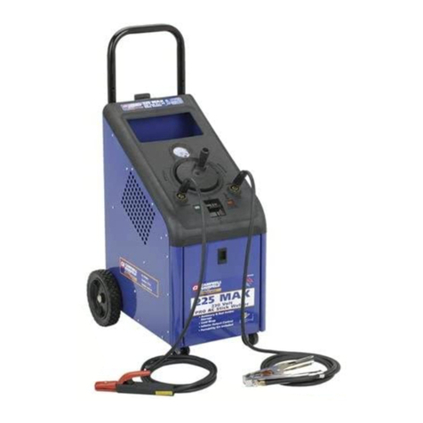
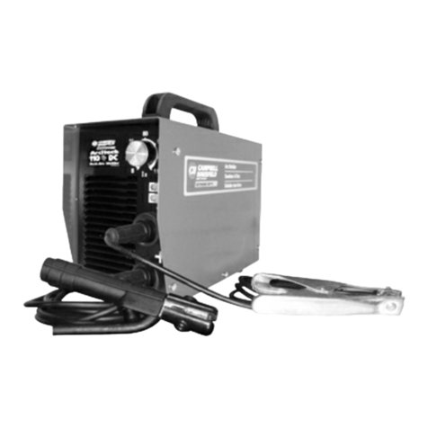
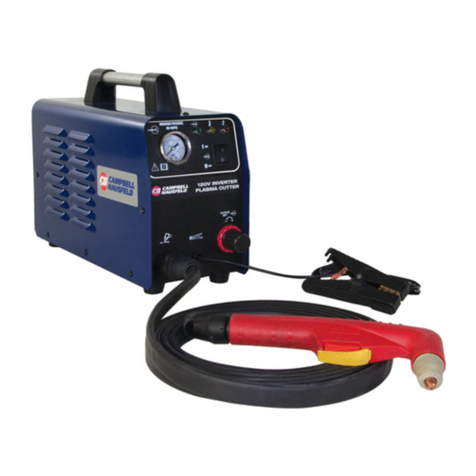
manuals.online logo
Brands
  1. Home
  2. •
  3. Brands
  4. •
  5. Campbell Hausfeld
  6. •
  7. Welding System
  8. •
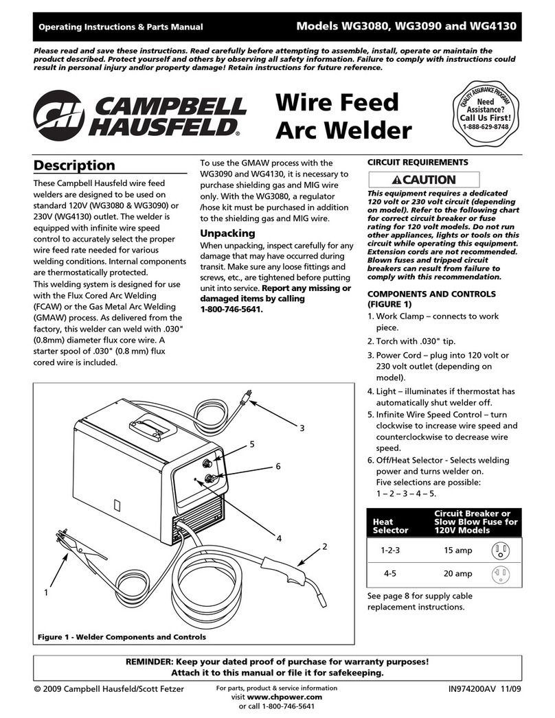
  9. Campbell Hausfeld WT6000 User manual

Campbell Hausfeld WT6000 User manual

Please read and save these instructions. Read carefully before attempting to assemble, install, operate or maintain the product described.
Protect yourself and others by observing all safety information. Failure to comply with instructions could result in personal injury and/or
property damage! Retain instructions for future reference.
S’il vous plaît lire et conserver ces instructions. Lire attentivement avant de monter, installer, utiliser ou de procéder à l’entretien du produit
décrit. Se protéger ainsi que les autres en observant toutes les instructions de sécurité, sinon, il y a risque de blessure et/ou dégâts matériels!
Conserver ces instructions comme référence.
Sírvase leer y guardar estas instrucciones. Lea con cuidado antes de tratar de armar, instalar, manejar o darle servicio al producto descrito en
este manual. Protéjase Ud. y a los demás observando todas las reglas de seguridad. El no seguir las instrucciones podría resultar en heridas y/o
daños a su propiedad. Guarde este manual como referencia.
IN211300AV 8/01
Instruction Manual Model WT6000
Instructions D’Utilisation Modéle WT6000
Manuel De Instrucciones Modelo WT6000
BUILT TO LAST
TM
fitting on the rear of the welder and
the other end to the fitting on the
regulator using hose clamps on each
connection. Make sure the gas hose is
not kinked or twisted.
4. Once again, stand opposite the
cylinder outlet and slowly open the
cylinder valve. Inspect for leaks in the
connections.
5. This regulator is factory preset at
30cfh. No adjustment is necessary.
Also, a pop-out indicator in the end of
the regulator shows the amount of
gas left in the cylinder. When not
extended, the cylinder is
approximately 10 minutes away from
empty.
6. Remember to close the gas valve
when finished welding.
General Safety
Cylinders can explode if
damaged. Shielding gas
cylinders contain gas
under high pressure.
• Protect compressed gas cylinders from
excessive heat, mechanical shocks, and
arcs.
• Install and secure cylinders in an
upright position by chaining them to
stationary support or equipment
cylinder rack to prevent falling or
tipping.
• Never allow a welding electrode to
touch any cylinder.
• Turn face away from valve outlet
when opening cylinder valve.
• Keep protective cap in place over valve
except when cylinder is in use or
connected for use.
• Read and follow instructions on
compressed gas cylinders, associated
equipment, and CGA publication P-1.
Never use
flammable gasses
with MIG welders. Only inert or non-
flammable gasses are suitable for
MIG welding. Examples are carbon
dioxide, argon, helium, or mixtures of
one or more of these gasses.
Never lift cylinders
off the ground by
their valves, caps, or with chains or
slings.
POLARITY
For gas shielded welding, plug the cable
coming out of the torch into the (+) socket
and the ground clamp cable into the (-)
socket on the welder.
GAS TYPES
There are 3 types of gas generally used for
gas metal arc welding; 100% argon, a
mixture of 75% argon and 25% carbon
dioxide (C25) or 100% carbon dioxide. All can
be used, but the 75/25 mixture is
recommended for general welding. For
aluminum welding, use 100% Argon. Either
type gas may be obtained at your local
welding supply outlet. Secure cylinder in
!
WARNING
!
DANGER
!
DANGER
place on your welding machine or other
support to prevent the cylinder from falling
over.
REGULATOR
This regulator is designed to be used with
straight Argon or Argon mix gas. A
threaded adapter is needed if CO2is used.
An adapter is available at your local
welding gas supplier to change between
the two.
HOOKUP PROCEDURE
Cylinder gas is
under high
pressure. Point cylinder outlet away
from yourself and any bystanders
before opening.
1. With the cylinder securely installed,
remove the cylinder cap, stand to the
side of the cylinder opposite the outlet,
and open the valve slightly, turning
counterclockwise. When gas is emitted
from the cylinder, close the valve by
turning clockwise. This will blow out
dust or dirt that may have accumulated
around the valve seat.
2. Install the gas regulator onto the gas
cylinder and tighten the stem nut
securely to the gas valve.
3. Install one end of the gas hose to the
!
WARNING
Cap
Chapeau
Tapa
CO2 Adapter
Adaptateur CO2
Adaptador para CO2
Pop-out
indicator
Indicateur sortant
Indicador
Figure 1 Hookup –Branchement –Conexiones
Argon or Argon Mix Installation
Installation d’Argon ou Mélange d’Argon
Installación para soldar con Argón o mezcla de Argón
CO2Installation
Installation CO2
Instalación del CO2
Mig Kit
Nécessaire Mig
Juego para soldar al estilo Mig
For parts, product & service information
visit www.chpower.com
© 2001 Campbell Hausfeld
2
Installation Instruction Manual
Généralités Sur La Sécurité
Les
bou-
teilles peuvent exploser si endom-
magées. Les bouteilles de gaz cont-
iennent du gaz sous haute pression.
• Protéger les bouteilles de gaz
comprimé contre la chaleur
excessive, les chocs mécaniques et
les arcs.
• Installer et fixer les bouteilles dans
une position verticale en utilisant
une chaîne sur un support
stationnaire ou un support de
bouteille pour éviter le
renversement ou le basculage.
• Ne jamais permettre que
l’électrode de soudage touche une
bouteille.
• Tourner le visage à l’écart de la
sortie de la soupape pendant
l’ouverture de la soupape de
bouteille.
• Garder le chapeau protecteur en
place sur la soupape sauf si la
bouteille est soi en service ou
branchée pour service.
• Lire et suivre les instructions pour
les bouteilles de gaz et autre
équipement ainsi que la publication
CGA P-1.
Ne
jamais
utiliser les gaz inflammables avec les
soudeurs MIG. Seuls les gaz
inertes ou non-inflammables sont
convenables pour le soudage MIG.
Exemples: bioxyde de carbone.
argon, hélium ou un mélange d’un
ou plus de ces gaz.
Ne
ja-
mais soulever les bouteilles par
leurs soupapes, chapeaux ou avec
les chaînes ou élingues.
POLARITÉ
Pour le soudage à gaz, brancher le câble
du chalumeau dans la prise (+) et le
câble du collier de mise à la terre dans la
prise (-) du soudeur.
TYPES DE GAZ
Il y a 3 types de gaz populaires pour le
soudage à l’arc avec gaz; 100% argon,
un mélange de 75% argon et 25% gaz
carbonique (C25) ou 100% gaz
carbonique. Le mélange 75/25 est
recommandé pour le soudage général
(mais tous types peuvent être utilisés).
Pour le soudage d’aluminium, utiliser
100% argon. Fixer la bouteille en place
sur votre soudeur ou sur un autre support
pour éviter le basculage de la bouteille.
RÉGULATEUR
Ce régulateur a été conçu pour
l’utilisation avec le gaz Argon ou
mélange d’Argon. Un adaptateur
fileté est nécessaire si le gaz
carbonique est utilisé. L’adaptateur
est disponible chez votre marchand de
gaz pour soudage.
BRANCHEMENT
Les
bou-
teilles de gaz sont sous haute
!
AVERTISSEMENT
!
AVERTISSEMENT
!DANGER
!DANGER
pression. Diriger l’orifice d’échapp-
ement à l’écart de soi-mème ou
d’autres personnes avant de l’ouvrir.
1. Une fois que la bouteille est bien
installée, enlever le chapeau de la
bouteille, se tenir au bord opposé de
l’orifice d’échappement et ouvrir la
soupape un peu en tournant à la
gauche. Quand le gaz sort de la
bouteille, fermer la soupape en
tournant à la droite. Ceci sert à purger
la poussière qui peut s’accumuler
autour de la siège de soupape.
2. Installer le régulateur de gaz sur la
soupape de la bouteille de gaz et
serrer l’écrou avec sûreté à la soupape
de gaz.
3. Installer un bout du tuyau de gaz au
raccord situé en arrière du soudeur et
l’autre bout du tuyau au raccord du
régulateur en utilisant des colliers de
serrage sur chaque raccordement.
Assurer que le tuyau n’est pas tortillé.
4. Se positionner au bord opposé de
l’orifice d’échappement de la
bouteille et ouvrir la soupape
lentement. Inspecter pour des fuites
dans l’endroit des raccordements.
5. Ce régulateur est réglé d’avance à
30cfh. Aucun ajustement est
nécessaire. Un indicateur sortant
situé au bout du régulateur indique la
quantité de gaz restant dans la
bouteille. Si l’indicateur n’est pas
étendu, il rest approximativement 10
minutes dans la bouteille.
6. Fermer la soupape de gaz à la fin du
travail.
Informaciones Generales de
Seguridad
Los
cilindros
dañados pueden explotar. Estos
cilindros contienen gas a alta
presión. Si está dañado el cilindro
puede explotar.
• Proteja los cilindros de gas
comprimido contra calor excesivo,
golpes y arcos eléctricos.
• Instale los cilindros en posición
vertical y asegúrelos con una cadena a
alguna pieza fija o a la base para
evitar que se caigan o volteen.
• Nunca permita el contacto entre el
electrodo de soldar y los cilindros.
• Nunca mire directamente hacia la
válvula de salida cuando vaya a abrir
la válvula del cilindro.
• Mantenga la tapa de protección en la
válvula excepto cuando esté usando el
cilindro o esté conectado.
• Lea y siga las instrucciones sobre
cilindors de gas comprimido y equipos
relacionados disponibles en su país.
Nunca
use
gases inflamables para soldar con
soldadoras tipo MIG. Sólo debe usar
gases inertes o no inflamables con
las soldadoras MIG. Por ejemplo
puede usar argón, helio o mezclas de
algunos de estos gases.
Nunca
tome los
cilindros por las válvulas o tapas ni
!ADVERTENCIA
!PELIGRO
!PELIGRO
use cadenas o eslingas para
cargarlos.
POLARIDAD
Para soldar con gas , conecte el cable que
sale del soplete al tomacorrientes (+) y el
cable de la pinza para conexión a tierra al
tomacorrientes (-). Para soldar con
fundente revestido (sin-gas), conecte el
soplete al (-) y la conexión a tierra al (+)
de la soldadora.
TIPOS DE GASES
Hay 3 tipos de gases que generalmente se
usan para soldar con arco; 100% argón,
una mezcla de 75% argón y 25% dióxido
de carbono (C25) o 100% dióxido de
carbono. Todos se pueden usar, pero la
mezcla 75/25 es la recomendada para todo
tipo de soldaduras. Para soldadura de
aluminio, utilice100% de argón. En
cualquier tienda especializada en artículos
para soldar puede compar los cilindros de
estos gases. Cerciórese de que el cilindro
esté bien sujeto para evitar que se caiga.
REGULADOR/MEDIDOR DE FLUJO
Este regulador está diseñado para usarse con
Argón puro o mezclas de Argón. Deberá
utilizar una adaptador con roscas para usar
CO2. Este adaptador está disponible en
tiendas especializadas en el ramo.
PARA HACER LAS CONEXIONES
Los
cilin-
dros de gas están bajo alta presión.
Dirija la salida del cilindro en
sentido opuesto a Ud. u otras
personas antes de abrirlo.
1. Una vez que el cilindro esté bien
instalado, destápelo, párese al otro
lado de la salida y abra la válvula un
poco (gírela en sentido contrario a las
agujas del reloj) . Cuando comience a
salir gas del cilindro, gire la válvula en
el mismo sentido de las agujas del reloj
para cerrarla. Ésto eliminará cualquier
acumulación de polvo o basura que
haya en los alrededores de la válvula.
2. Instale el regulador/medidor de flujo
de gas en la válvula del cilindro y
apriete la tuerca del vástago para
conectarlo a la válvula del gas.
3. Instale uno de los extremos de la
manguera de gas al conector ubicado
en la parte posterior de la soldadora y el
otro extremo al conector del regulador
(use abrazaderas en cada extremo).
Cerciórese de que la manguera de gas
no esté enrollada o torcida.
4. Una vez más, párese al otro lado de la
salida y abra la válvula un poco. Revise
a ver si hay fugas.
5. Este regulador/medidor de flujo
viene fijado de fábrica a 30 pies
cúbicos por hora. No necesita
ajustarlo. Igualmente, un indicador
incorporado al extremo del regulador
le permite leer la cantidad de gas que
hay en el cilindro. Cuando este
indicador no está extendido, todavia
tendrá suficiente gas en el cilindro
para trabajar unos 10 minutos más.
6. Recuerde cerrar la válvula del gas
cuando termine de soldar.
!ADVERTENCIA
www.chpower.com

Other Campbell Hausfeld Welding System manuals

Campbell Hausfeld WF1800 Instructions for use

Campbell Hausfeld

Campbell Hausfeld WF1800 Instructions for use

Campbell Hausfeld WT2530 User manual

Campbell Hausfeld

Campbell Hausfeld WT2530 User manual

Campbell Hausfeld IN974200AV Service manual

Campbell Hausfeld

Campbell Hausfeld IN974200AV Service manual

Campbell Hausfeld Welder / Generator GW4500 Service manual

Campbell Hausfeld

Campbell Hausfeld Welder / Generator GW4500 Service manual

Campbell Hausfeld WS0900 Service manual

Campbell Hausfeld

Campbell Hausfeld WS0900 Service manual

Campbell Hausfeld WS0970 Service manual

Campbell Hausfeld

Campbell Hausfeld WS0970 Service manual

Campbell Hausfeld WG3060 Instructions for use

Campbell Hausfeld

Campbell Hausfeld WG3060 Instructions for use

Campbell Hausfeld GW4502 Service manual

Campbell Hausfeld

Campbell Hausfeld GW4502 Service manual

Campbell Hausfeld WG3020 Instructions for use

Campbell Hausfeld

Campbell Hausfeld WG3020 Instructions for use

Campbell Hausfeld WT5000 Manual

Campbell Hausfeld

Campbell Hausfeld WT5000 Manual

Campbell Hausfeld WK250000AV Service manual

Campbell Hausfeld

Campbell Hausfeld WK250000AV Service manual

Campbell Hausfeld WF2050 Instructions for use

Campbell Hausfeld

Campbell Hausfeld WF2050 Instructions for use

Campbell Hausfeld WF2034 Instructions for use

Campbell Hausfeld

Campbell Hausfeld WF2034 Instructions for use

Campbell Hausfeld WG3013 Service manual

Campbell Hausfeld

Campbell Hausfeld WG3013 Service manual

Campbell Hausfeld WG3080 Service manual

Campbell Hausfeld

Campbell Hausfeld WG3080 Service manual

Campbell Hausfeld WS0970 Service manual

Campbell Hausfeld

Campbell Hausfeld WS0970 Service manual

Campbell Hausfeld WG4000 Service manual

Campbell Hausfeld

Campbell Hausfeld WG4000 Service manual

Campbell Hausfeld WG204498AJ User manual

Campbell Hausfeld

Campbell Hausfeld WG204498AJ User manual

Campbell Hausfeld WS0900 Instructions for use

Campbell Hausfeld

Campbell Hausfeld WS0900 Instructions for use

Campbell Hausfeld WS090001AV Installation and operating instructions

Campbell Hausfeld

Campbell Hausfeld WS090001AV Installation and operating instructions

Campbell Hausfeld WF2150 Service manual

Campbell Hausfeld

Campbell Hausfeld WF2150 Service manual

Campbell Hausfeld WG2060 Service manual

Campbell Hausfeld

Campbell Hausfeld WG2060 Service manual

Campbell Hausfeld ARCITECH WS2100 Service manual

Campbell Hausfeld

Campbell Hausfeld ARCITECH WS2100 Service manual

Campbell Hausfeld WS2800 Instructions for use

Campbell Hausfeld

Campbell Hausfeld WS2800 Instructions for use

Popular Welding System manuals by other brands

GYS WS5-4L user manual

GYS

GYS WS5-4L user manual

Riland ZX7 400GT user manual

Riland

Riland ZX7 400GT user manual

Miller Axcess 675 owner's manual

Miller

Miller Axcess 675 owner's manual

HBS KAH 412 LA operating manual

HBS

HBS KAH 412 LA operating manual

Soyer BMK-8i operating instructions

Soyer

Soyer BMK-8i operating instructions

Draper stormforce 53084 manual

Draper

Draper stormforce 53084 manual

GYS GYSPOT PTI s7 user manual

GYS

GYS GYSPOT PTI s7 user manual

Lincoln Electric LF 56D Operator's manual

Lincoln Electric

Lincoln Electric LF 56D Operator's manual

Crossfire Invercut 40D owner's manual

Crossfire

Crossfire Invercut 40D owner's manual

Air Liquide SAXO 1500 Safety instruction for use and maintenance

Air Liquide

Air Liquide SAXO 1500 Safety instruction for use and maintenance

Defort DWI-200S user manual

Defort

Defort DWI-200S user manual

Lincoln Electric Precision TIG 375 Service manual

Lincoln Electric

Lincoln Electric Precision TIG 375 Service manual

Cebora SOUND MIG 3840/T Pulse Service manual

Cebora

Cebora SOUND MIG 3840/T Pulse Service manual

Miller Electric Big 40 C owner's manual

Miller Electric

Miller Electric Big 40 C owner's manual

GUS MULTIPEARL 200-2 manual

GUS

GUS MULTIPEARL 200-2 manual

Miller Electric SRS-1000A1 owner's manual

Miller Electric

Miller Electric SRS-1000A1 owner's manual

Chimera ARC-110 operating manual

Chimera

Chimera ARC-110 operating manual

Kemppi KEMPACT MIG 2520 operation instruction

Kemppi

Kemppi KEMPACT MIG 2520 operation instruction

manuals.online logo
manuals.online logoBrands
  • About & Mission
  • Contact us
  • Privacy Policy
  • Terms and Conditions

Copyright 2025 Manuals.Online. All Rights Reserved.