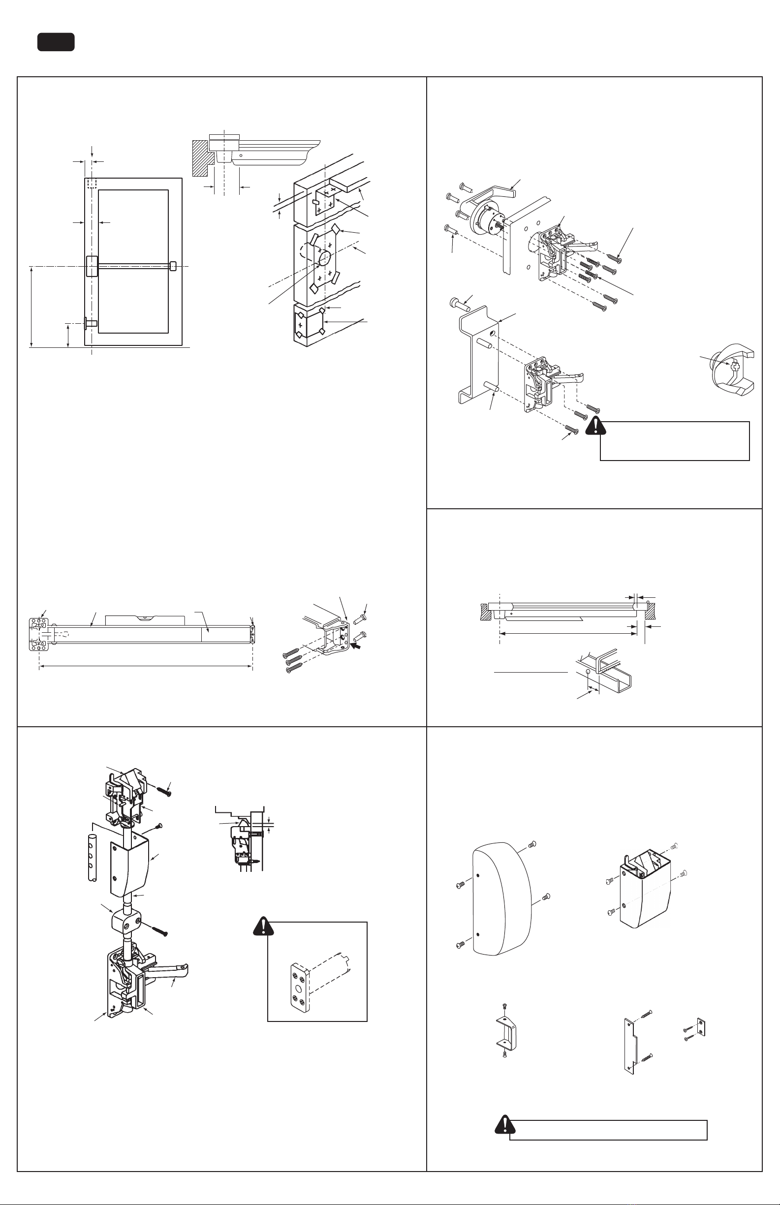
Top latch
chassis
assembly
Retractor
Adjuster
pin
Top
cover
Top rod
Top rod
guide
Lift arm
Main slide
(4) #12 flat
head screws
Top
latch
strike
NOTE: Shim top strike to
obtain 1/8" (3.2 mm) gap
(if required)
1/8" (3.2 mm)
gap required
Main chassis
assembly
Previously prepared fire labelled doors must meet the
requirements in note #2 in General Notes on Page 1
1
2
3
4
5
6
1. MARK VERTICAL AND HORIZONTAL REFERENCE LINES ON DOOR
Determine the backset based on door lock stile width, and locate the vertical reference line.
a. If lock stile is 4 1/2" (114.3 mm) wide or wider, use 2 3/4" (69.9 mm) backset.
b. If lock stile is less than 4 1/2" (114.3 mm) wide, place the backset at 1/2 of the exposed lock stile width.
2. DOOR PREPARATION AND EXIT DEVICE INSTALLATION
A. Prepare Door, Frame and Floor
1) It is recommended to reinforce the door at the exit device mounting locations and make all required cutouts and holes larger
than 1" (25.4 mm) diameter at the door fabrication shop using dimensions provided in the installation templates.
2) Otherwise, mark the vertical and horizontal reference lines on the door interior surface of the door using provided dimensions.
3) Main Chassis:
a) Position main template on interior door surface by aligning the vertical and horizontal lines and mark the four (4) main
chassis mounting holes.
b) Drill all main chassis mounting holes as per supplied template instructions.
c) If a trim is used, use also the appropriate trim installation template (refer to section 4).
4) Top Latch Chassis and Strike:
a) Position top latch template on interior door surface by aligning the vertical reference line at the indicated dimension from
the frame soffit and mark the four (4) top latch chassis mounting holes on the door and four (4) holes on the frame soffit
for the strike
b) Drill all top latch chassis and strike mounting holes as per supplied template instructions.
B. Install Exit Device
1) If no trim is used, install main chassis using four (4) thru-bolts or drill and tap for #10-24 UNC if door is properly reinforced.
2) Level rail assembly and attach the rail mounting bracket to door using two (2) thru-bolts or drill and tap for three (2) #10-24
UNC machine screws if door is properly reinforced and prepped. Use bracket as template.
3) If trim is used refer to section 4.
Backset
Finished Floor
Vertical
Reference Line
Horizontal
Reference Line
41"
(1041 mm)
Frame Door Stop
Top Chassis
Template
Tape
Horizontal
Reference
Line
Vertical Reference Line
stop thickness
2 1/8" (54 mm) ø
bore when knob
or lever trim is used
Soffit
Lock
stile
3. INSTALL TOP & CHASSIS AND STRIKE
1. Mount top latch chassis on door using four (4) machine screws or machine screws with thru-bolt sexnuts.
2. Mount top strike at location determined in section 2, secure with two (2) machine screws. (refer to template)
3. Screw top rod (longer rod) into main slide (see above left illustration).
4. Slide guide onto top rod and insert rod into top latch chassis, insert adjuster pin through retractor and middle hole in rod.
Use the appropriate hole in rod to ensure proper latch engagement with strike. Adjust strike position as required then
fasten screws. If shorter rod is required cut rod to required length and drill a 1/8" (3.2 mm) dia. hole through the rod.
5. Ensure top latch engages and operates properly with strike, adjust position if required. Secure with two additional screws.
6. Fasten rod guides at mid-length of rods. Pre-drill 1/8" (3 mm) holes for wood screws, or drill & tap for # 10-24 UNC
machine screws.
7. Install auxiliary fire latch as per attached template and instructions.
Lever or Knob Trim
(9500TL or 9500TK)
Thru-bolt
sexnut
Pull Trim
(9500TPDT)
Ensure that the
spindle does not
extend past the
cam surface
4. INSTALL TRIM
a) Refer to applicable trim template and installation instructions: drill/bore holes on door exterior
surface as per trim installation instructions.
b) Use mounting hardware supplied with the exit device and with applicable trim.
c) Do not over-torque trim mounting screws, and ensure door surface is not bowed-in.
CAUTION: Over-torquing may cause exit device to jam.
d) Verify that the trim operation retracts the exit device latch.
TYPICAL TRIM INSTALLATIONS
For escutcheon trim (9500TE) installations, refer to the template and installation instructions
supplied with the applicable trim.
NOTE: Vertical rods must be properly aligned to eliminate any friction or binding that may interfere with the
exit device smooth operation
Door
Attach pull trim
and chassis to door
using hardware
supplied with the
pull trim
Trim and chassis
mounting screws
Main
chassis
A
A
A
A
B
B
B
B
Main Chassis
mounting
hardware
[ 4-screws (A) ]
Trim
mounting
hardware
[ 4-screws (B) ]
Thru-bolt
sexnut
Thru-bolt
sexnut
Don't cut closer than 1 3/4"(45 mm) from lower pivot
(remove sliding cover to locate pivot)
minimum
1/2" (12.7 mm)
X
Y
minimum
1 3/4" (45 mm)
For door with stile, cut off must leave
minimum 1/2" (12.7 mm) overlap with rail
Backset or vertical
Reference Line
5. MODIFY RAIL
a) Confirm length of device and determine if rail cutting is required.
b) Determine length 'X' by subtracting 1 3/4" (45 mm) from 'Y'. Mark cut-off point on rail and sliding
cover and cut-off.
c) Deburr and remove all sharp edges after cutting and install as per section 2.
CUT OFF & DEBURR
Attach cover to top
chassis with (4) four screws
(c)
On doors and frames that have been prepared for
use with strikes and latches, install the appropriate
filler plates using flat head wood or machine screws
Latch Filler
Plate
Strike Filler
Plate
(d)
Attach cover to main chassis
assembly with four (4)
flat head machine screws
Attach end cap to rail mounting
bracket with two (2)
flat head machine screws
(a)
(b) (e)
6. INSTALL COVERS
a) Attach the main chassis cover to the main chassis using supplied machine screws.
b) Attach the rail end cap to the rail mounting bracket using supplied machine screws.
c) Attach the the top chassis cover using supplied machine screws.
d) If required, fill existing frame strike location on door frame with the strike filler plate using
supplied mounting screws.
e) If required, fill existing latch faceplate location on door edge with the latch filler plate using
supplied mounting screws.
Four (4) machine
screws or
thru-bolts with
sexnuts
4
9500FL-INST-EN-R2016-09 2/2
Auxiliary fire latch:
must be installed as per
included template and
instructions.
Exposed
stile width
36" model = 30 11/16" (780 mm)
48" model = 42 11/16" (1088 mm)
REFERENCE
Push bracket
tightly against
rail assembly
Level
Rail
Assembly
Main Chassis
Rail
Mounting
Bracket
Sliding Cover
or Alarm Panel
Attach rail mounting bracket
to door with two (3) machine
screws or with two (2)
thru-bolts and sexnuts
(if required)
#10-24
Sexnut
For Fire labeled doors: it is recommended
that all cutouts and holes be done at the
fabrication shop, as field modifications
may impact the door fire rating
9500FL EXIT DEVICE - FIRE RATED (F) LESS BOTTOM SURFACE ROD (L)
INSTALLATION INSTRUCTIONS
9500
SERIES
6"
(152.4mm)
Auxiliary Latch
Template


