Cannondale 2011 LEFTY 126564.PDF User manual

OWNER’S MANUAL SUPPLEMENT
2011 LEFTY
126564.PDF
WARNING READ THIS SUPPLEMENT AND YOUR CANNONDALE BICYCLE OWNER’S MANUAL.
Both contain important safety information. Keep both for future reference.

This manual meets EN standards
14764, 14766, and 14781.
Vélo certifié conforme aux exigences du décret
N 95-937 du 24 août 1995 norme NFR030
In this supplement, particularly important information is presented in the following ways:
WARNING Indicates a hazardous situation which, if not
avoided, could result in death or serious injury.
NOTICE Indicates special precautions that must be taken to
avoid damage.
TIP A TIP provides helpful information.

1
EN - 09/10
CONTENTS
SAFETY INFORMATION ........................................ 1
About this Supplement........................................... 1
Intended Fork Use................................................... 2
Fork Damage........................................................... 3
Disassembly/Modication ...................................... 3
Fork Under High-Pressure ....................................... 3
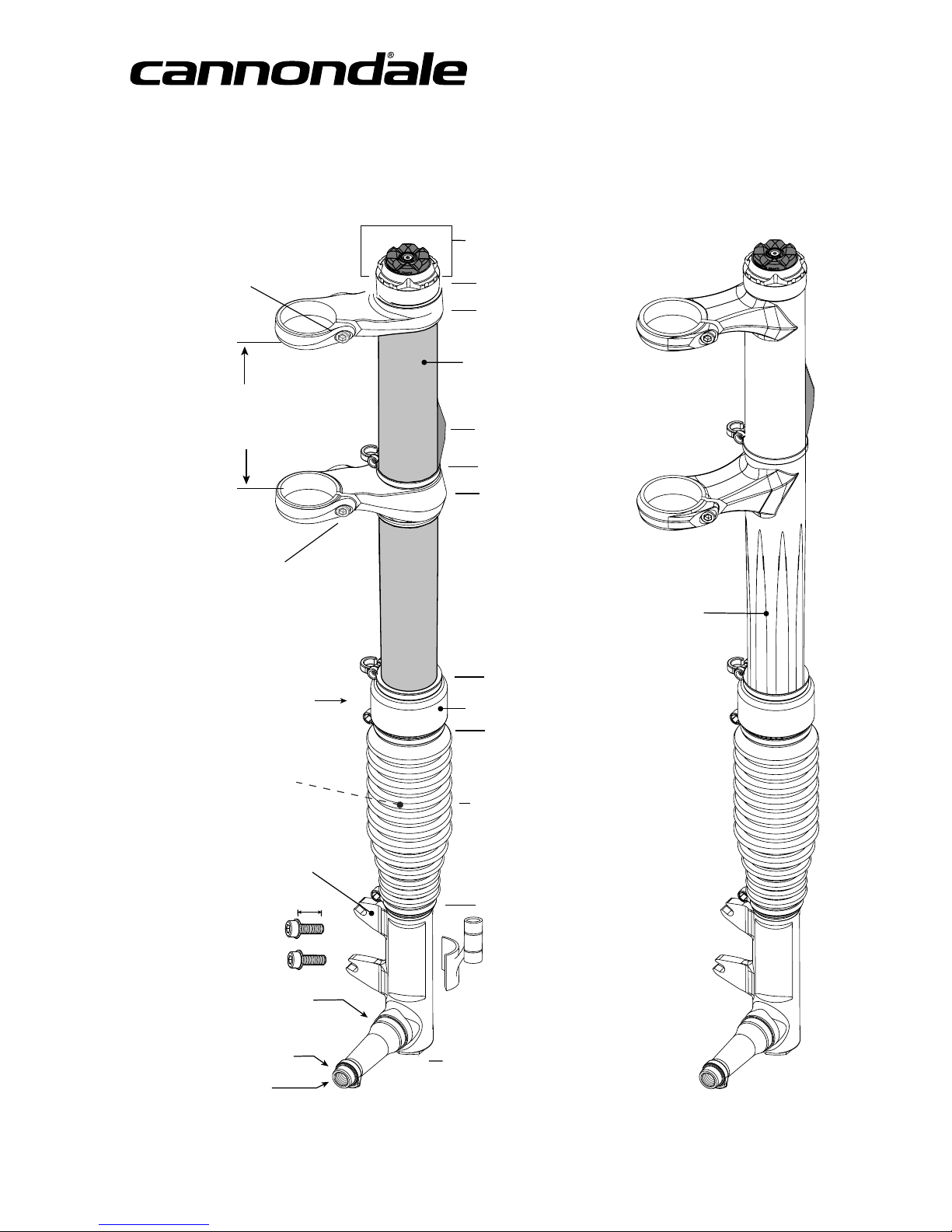
FORK IDENTIFICATION......................................... 4
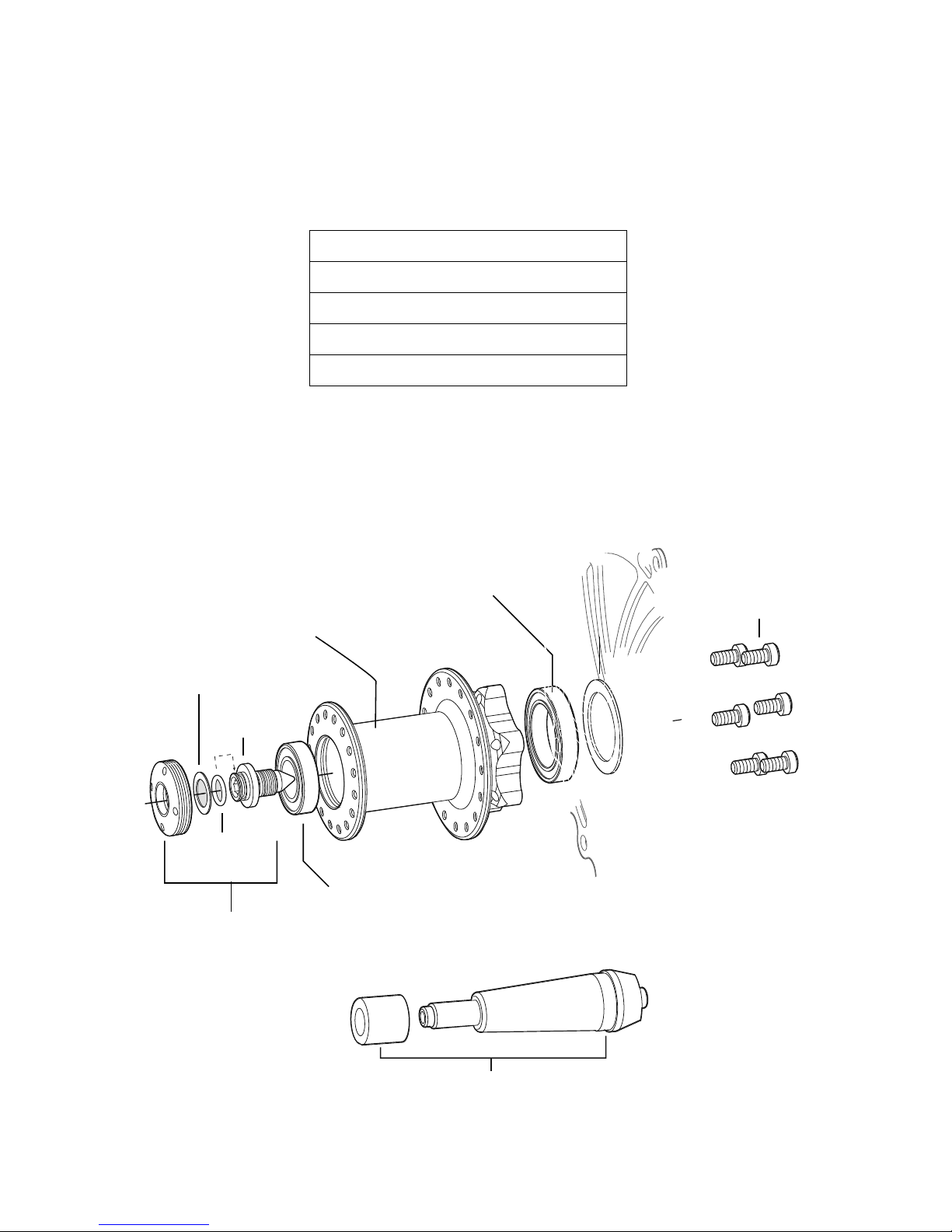
WHEELHUB......................................................... 5
FRONT WHEEL..................................................... 6
Removal ................................................................ 6
Installation ............................................................. 7
ADJUSTMENT
XLR Hydraulic Remote............................................. 8
PBR ................................................................ 8
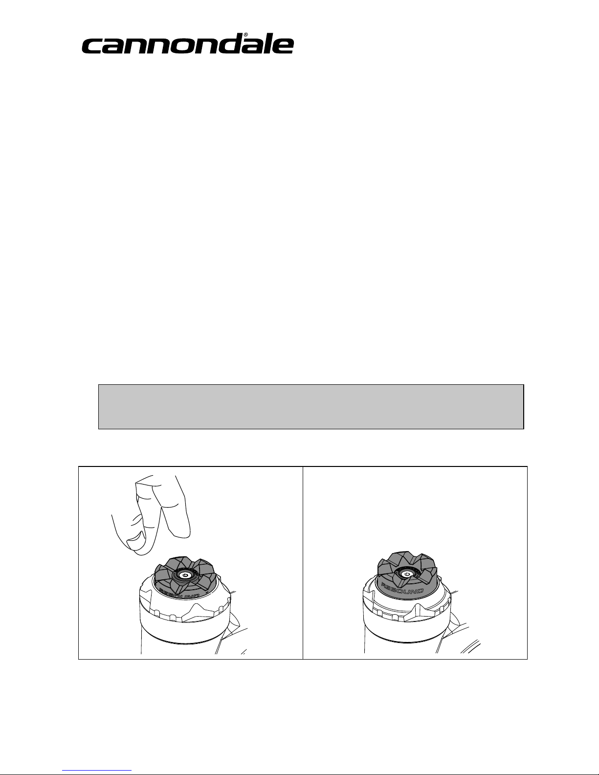
XLR Rebound .......................................................... 9
PBR Rebound.......................................................... 9
Recommended Air Pressure .................................. 10
OPI STEM........................................................... 12
11/8”STEERERADAPTERKITS.......................... 14
MAINTENANCE .................................................. 16
Schedule.............................................................. 16
Cleaning .............................................................. 17
Frame Bumper Replacement ................................ 17
Boot Inspection..................................................... 18
Clean/Re-Oil Air Filter ........................................... 19
Clean/Re-grease Telescope ................................... 20
NeedleBearing Reset............................................ 23
REPLACEMENT PARTS........................................ 24
Please note that the specications and information
in this manual are subject to change for product
improvement. For the latest product information, go
to http://www.cannondale.com/tech_center/
SAFETY INFORMATION
About This Supplement
CannondaleOwner’sManual Supplements provide important
model specic safety, maintenance, and technical information.
They are not replacements for your Cannondale Bicycle
Owner’s Manual.
This supplement may be one of several for your bike. Be sure
to obtain and read all of them.
Ifyou need amanual or supplement, or have aquestion about
your bike, please contact your CannondaleDealer immediately,
or call us at one of the telephone numbers listed on the back
cover of this manual.
You can download Adobe Acrobat PDF versions of any
CannondaleOwner’sManualsor Supplements from our
website: http://www.cannondale.com/bikes/tech.
t 5IJT NBOVBM JT OPU B DPNQSFIFOTJWF TBGFUZ PS TFSWJDF
manual for your bike.
t 5IJT NBOVBM EPFT OPU JODMVEF BTTFNCMZ JOTUSVDUJPOT GPS
your bike.
t "MM$BOOPOEBMFCJLFTNVTUCFDPNQMFUFMZBTTFNCMFEBOE
inspected for proper operation by aCannondaleDealer
before delivery to the owner.
WARNING
This supplement may include procedures beyond the scope
of general mechanical aptitude.
Special tools, skills, and knowledge may be required.
Improper mechanical work increases the risk of an
accident. Any bicycleaccident has risk of serious injury,
paralysisordeath.Tominimizeriskwe stronglyrecommend
that owners always have mechanical work done by an
authorized Cannondaleretailer.

2
INTENDED FORK USE
LEFTY SPEED 100 mm,
LEFTY 29’er 90mm
LeftyMAX 140 mm,
LeftyUltra 120 mm
Cross-Country, Marathon, HardtailsAll Mountain, Overmountain
ASTMCONDITION 3
ASTM F2043
ASTMCONDITION 4
ASTM F2043
FORK INTENDED -For cross-country riding and racing
which ranges from mildto agressive over intermediate
terrain (e.g., hillywith small obstacles like roots, rocks, loose
surfaces and hard pack and depressions). There are no large
“sick drop” or drop os, jumps or launches (wooden struc-
tures, dirt embankments) requiring long suspension travel
or heavy duty components. Cross-country and marathon
equipment (tires, shocks, frames, drive trains) are light-
weight, favoring nimblespeed over brute force. Suspension
travel is relativelyshort since the bike is intended to move
quicklyon the ground and not spend time in the air landing
hard and hammering through things.
FORK INTENDED -For trail and uphill riding. All-Mountain
bicycles are: (1) more heavy duty than cross country bikes
or trail bikes, but less heavy duty than Freeride bikes, (2)
lighter and more nimblethan Freeride bikes,
(3)heavier and have more suspension travel than across
country bike, allowing them to be ridden in more dicult
terrain, over larger obstacles and moderate jumps, (4)
intermediate in suspension travel and use components that
t the intermediate intended use, (5)cover afairlywide
range of intended use, and within this range are models
that are more or less heavy duty. Talkto your retailer about
your needs and these models.
FORK NOT INTENDED -For use in extreme forms of jump-
ing/riding such as hardcore mountain, Freeriding, Downhill,
North Shore, Dirt Jumping, Hucking etc.
FORK NOT INTENDED -For use in extreme forms of jump-
ing/riding such as hardcore mountain, Freeriding, Downhill,
North Shore, Dirt Jumping, Hucking etc.
WARNING
UNDERSTAND YOUR FORK AND ITSINTENDED USE. USING YOUR FORK THEWRONG WAY ISDANGEROUS.
Industry usage Conditions 1-5 are generalized and evolving. Consultyour CannondaleDealer about how you intend to use
your bike/fork. Please read your Cannondale Bicycle Owner’s Manual for more information about Intended Use
and Conditions 1-5.

3
126564.PDF
FORK DAMAGE
WARNING
STOP RIDING ADAMAGED FORK IMMEDIATELY.
The following conditions indicate that serious fork damage
is present:
1. Any unusual“klunking” or knocking noises.
2. Achange in fork travel.
3.An over-extended, elongated, or compressed boot.
4.Changes from the way the fork had been working
5.Loss of adjustment features, oil leaks, or air leaks.
6.Crash or impact damage (deep scratches, gouges,
dents, or bending)
7.Small cracks under the bolthead of upper and lower
clamp bolts. This inspection requires the removal of
the bolts.
Horizontal cracks above and below the intersection
of the upper and lower clamps with the outer tube
portion of the Lefty carbon structure.
Vertical cracks in the outer tube (where the races
and needlebearings run). These may show as long,
straight lines perhaps several lines parallel to each
other.
Also, please read Inspect For Safety in PART II,Section D. of
your Cannondale Bicycle Owner’s Manual.
HAVEANY DAMAGED FORK INSPECTED AND DAMAGE
REPAIRED BY YOUR CANNONDALE DEALER. YOU CAN
BESEVERELY INJURED, PARALYZED OR KILLED INAN
ACCIDENT IF YOU IGNORE THISWARNING.
The MAINTENANCE section of this supplement includes
information about regular maintenance practices that can
keep your fork in good operating condition.
DISASSEMBLY OR MODIFICATIONS
WARNING
DO NOT DISASSEMBLE OR MODIFY THEFORK.
Improper service or modication can lead to serious fork
damage or serious personal injury. Ifyour fork requires
service, please take it to an Authorized CannondaleDealer.
DO NOT:
1. Drill,le, cut or remove material from any fork part.
2. Weld, clamp, or bond anything to the fork.
3.Attempt to remove or add the damping cartridge or
other internal fork parts.
The MAINTENANCE section of this manual indicates (*)
service items to be completed through an Authorized
CannondaleDealer. Your dealer can arrange for the
neccessary service through our Factory Tech Room.
FORK UNDER HIGH-PRESSURE
WARNING
SERVICE BY PROFESSIONAL BIKEMECHANICONLY.
Special toolsare required. All air pressure must be
released before servicing any fork. Never attempt to
work on apressurized fork.
YOU CAN BESEVERELY INJURED, PARALYZED,
OR KILLED INAN ACCIDENT IF YOU IGNORE THIS
WARNING.

4
SERIAL NUMBER
Located on outertube
under the air lter
foam element.
16mm
ONE-PIECE INTEGRATION (O.P.I.)
INNERTUBE/SPINDLE
International Standard
BRAKE CALIPERMOUNTS
LOWERCLAMP(bonded alloy)
BOOT
FRAME BUMPER
AXLE BOLT THREADS
OUTERHUB BEARING LAND
INNERHUB BEARING LAND
CARBON OPI
UPPERCLAMP
OUTERCOLLAR (bonded alloy)
EXTERNAL ADJUSTMENTS
(PBR shown)
COMPUTER
SENSOR MOUNT
(OPTIONAL)
CLAMP
CLAMPw/guide
AIRPRESSURE ADJUSTMENT
AIRFILTERASSEMBLY
CLAMP
CLAMPw/guide
ONE-PIECE INTEGRATION (O.P.I.)
OUTER TUBE/ CLAMPS
CARBON FIBER OUTER TUBE
CLAMPBOLT
7-9 Nm, 62-80 InLbs
CLAMPWIDTH
4.5 in Headtube -137.6 mm
5.5 in Headtube -163.0 mm
CLAMPBOLT
7-9 Nm, 62-80 InLbs
FORK IDENTIFICATION

5
126564.PDF
WHEEL HUB
Lefty 24 And 32Spoke Hub Dimensions
Disc Flange Diameter 58 mm
Non Disc Flange Diameter 44.5 mm
Disc Flange ToCenter 35 mm
Non Disc Flange ToCenter 20 mm
CAP
Park SPA-1
AXLE BOLT
SEAL
INNERBEARING
WHEELHUB
OUTERBEARING
WASHER
O-RING
NO RIDE
WHEELTRUING TOOL - QCTL108/
15.0 Nm
DISC ROTOR BOLTS
6.2 Nm, Loctite 262
QC117/
KB61902/
KB61805/
QC118/
QC081/ (24 spk, 6bolt)
QC627/ (32spk, 6bolt)
I.D. xO.D. xThick
25 x37 x7mm
I.D. xO.D. xThick
15 x28 x7mm

6
FRONT WHEEL
Toremove the wheel:
1. Use a5 mm Allen key to loosen the brake caliper
mounting bolts enought to remove the brake caliper from
the mounting tabs.
Note brake alignment shims between brake bosses and
the caliper. Replace correctlyduring reinstallation.
2. Insert a5 mm Allen key into the axlehub boltand turn
the the hub extraction boltcounter-clockwise.
Continue turning the extraction boltuntil the wheel can
be removed easilyfrom the spindleend.
NOTICE
■Make sure the boltis completelydisengaged
before attempting to remove the wheel.Never
try to pull the wheel o forcefully.
■When the wheel is o,to keep dirt out, cover the
hub opening.
■Protect spindlefrom damage when wheel is
removed.

7
126564.PDF
Toinstall the wheel:
1. Inspect inside the wheel hub for contamination and
the condition of the hub seal.Take corrective action if
necessary.
Wipe the spindleclean with adry shop towel.
Applyahigh-quality bike grease to I.D. of the bearings
inside the hub.
2. Slide the wheel straight onto the spindle.
3.Turn the axleboltclockwise to engage the spindle
threads.
Make sure the wheel and spindleare supported
whiletightening the hub bolt.
4.Once the hub has been drawn onto the hub completely,
VTF UPSRVF XSFODI UP UJHIUFO UP öOBM /tN
*Ot-CT
3FJOTUBMMUIF CSBLFDBMJQFS 5JHIUFO CPMUT UP *Ot-CG
/tN
6.Spin the wheel to make sure it moves freely. Be sure to
test the brakes for proper operation before riding.
WARNING
DO NOT CONTAMINATEBRAKECALIPER, PADS, OR
ROTOR WITH GREASE.
WARNING
DO NOT RIDE WITHOUT APROPERLY MOUNTED,
ADJUSTED, AND FUNCTIONING FRONT BRAKE
SYSTEM.
The Lefty (disc/caliper) acts as an integral secondary wheel
retention system. Ifthe system is missing or improperly
installed, or if the wheel hub axleboltshouldloosen, the
front wheel couldslide o the spindleend.
When mounting IScompatiblebrake systems:
Follow brake manufacturer’sinstructions when mounting
the brake caliper to the spindlebrake bosses. Do not
modify the fork in any way.
PLEASE ASK YOUR CANNONDALE DEALER FOR HELP
WHEN INSTALLING COMPATIBLE FRONT BRAKE
SYSTEMS.
NOTICE
■LOCATEBRAKEROTOR BETWEEN THEPADS.
Replace shims that are in use, be sure the shims are
positioned between the caliper (adapter if any) and
inner face of the fork mounts, not under the head of
the caliper bolts.
■USE ONLY THELEFTY 16mm CALIPER BOLTSTO
MOUNT THEBRAKE.Longer bolts can resultin
contact with the brake rotor causing severe damage.
Check clearance between the bolttips and rotor after
remounting the caliper. Order replacement bolts -
Cannondalep/n LEFTYBOLTS/.
■MAKESURE THEBRAKEDISC CAN NOT MAKE
CONTACT WITH THEFORK BOOT.Arotating brake
disc can wear through the boot allowing contaminants
into the fork.

8
LOCKOUT ADJUSTMENT
XLR Hydraulic Remote
OPEN POSITION
Push black button to engage lockout.
LOCKED POSITION
Push black button again to return to open.
* NOTICE
DO NOT ROTATETHEGOLD DIAL!This is not an adjustment when used with Lefty. This dial has been set at the factory.
PBR
OPEN POSITION
Press blue button to engage lockout.
LOCKED POSITION
Press red knob to return to open.
**

9
126564.PDF
REBOUND ADJUSTMENT
XLR Rebound Dial
ROTATEDIAL INTHE“--” DIRECTION (COUNTER-CLOCKWISE) TOINCREASE REBOUND SPEED (FASTER).
ROTATEDIAL INTHE“+” DIRECTION (CLOCKWISE) TODECREASE REBOUND SPEED (SLOWER).
PBRRebound Dial
ROTATEDIAL INTHE“--” DIRECTION (COUNTER-CLOCKWISE) TOINCREASE REBOUND SPEED (FASTER).
ROTATEDIAL INTHE“+” DIRECTION (CLOCKWISE) TODECREASE REBOUND SPEED (SLOWER).

10
Recommended Air Pressure
RIDER(B)
NO RIDER(A)
SAG = A-B
“Attack”
Weight Distribution
50/50
“
A
“
tt
k
”

11
126564.PDF
Recommended Air Pressure
Toset air pressure
1. Make sure the bottom of the fork is clean. Remove the Schrader valve cap. Attach abicyclesuspension pump to the valve
end.
2. Pressurize the fork to an initial starting air pressure of 65-75% of rider weight.
3.Add or release air to achieve 20-30% sag.
MODEL MAXULTRA SPEED 29’ER
TOTAL TRAVEL(mm) 140 120100 90
MINIMUM SAG 20% (mm) 28 242018
B (mm) 660 640 635 645
MAXIMUM SAG 30% (mm) 4236 30 27
B(mm) 645 630 625 635
B= Overall Lefty length at sag .Measure the distance between bottom of outer collar to bottom of spindle.
PRESSURE LIMITS
Minimum: 50 psi, 3.4 bar
Maximum: 225 psi, 15.5 bar
2. Now, to ne tune the sag. Without arider, measure the fork from the bottom edge of the outer collar to the bottom
edge of the spindle. Next, have someone assist you. Sit on the bike with your feet on the pedalsand hands on
handlebar as if you were in ariding position; measure length (B), the fork compressed under your weight.
Tocalculate the sag, subtract :A-B= SAG (mm).
Add air pressure to decrease sag.
Release air pressure to increase sag.
NOTICE
MAKESURE THESUSPENSION PUMP AND FORK
SCHRADER VALVEARE CLEAN. Attaching to adirty
valve or with adirty pump end can resultin pumping
the dirt into the fork. This couldresultin damage
and air loss.
SUGGESTED SAG RANGE
XC- 20-25%
TRAIL20-30 %

12
OPI STEM
The following procedure shouldonlybe completed by aprofessional bike mechanic.
Before installation, make sure all part surfaces are clean. Applyahigh-quality bicyclebearing grease to the surfaces indicated.
See shaded areas in illustration, next page. Make sure both upper and lower head tube bearings are fullyseated in the headtube.
Follow these steps carefully:
1. Install the upper bearing seal onto the upper headtube bearing. The open side of the seal faces the bearing.
2. Position the Lefty onto the headtube by sliding the Lefty clamps over the head tube and seal.
3.Slide the nylon washer onto the OPI stem with rounded side facing the shoulder of the stem.
4.Applygrease to fullycover stem bearing surface and the internal steerer threads. Also applygrease to the inner race of the
upper and lower headtube bearings. Slide the desired number of spacers onto the stem. You may use 0-3 spacers onto the OPI
stem. Use onlyOPI spacers. See the warning below.
5.Make sure the Lefty is aligned over the head tube bearings, insert stem (with nylon washer, and desired spacers) through
upper clamp/seal and onto the bearing. With asoft mallet, carefullydrive stem straight down until fullyseated.
6.Next, install the nylon washer onto steerer with the rounded side of the washer facing the steerer bottom ange. Grease
entire steerer lower bearing surface and the steerer threads.
7.Insert steerer into bearing and carefullyhand thread into stem. Do not use atool.Continue hand threading until the steerer
contacts the lower clamp surface.
8.Tighten the steerer to 12 Nm using the ShimanoTL-FC33 bottom bracket tool and atorque wrench. This step draws the stem
and spacer stack to the upper clamp. When tightened, align the stem and onlyhand tighten the upper clamp bolt.
9.Re-tighten the steerer to 12 Nm, ensuring the stem and Lefty do not move relative to each other. Then, hand tighten the lower
clamp bolt.
10.Finish by tightening both the upper and lower Lefty clamp bolts to the nal torque of 7 -9 Nm.
11. ApplyLoctite 242and tighten the handlebar clamp bolts evenlyand equallyin across pattern to 6 Nm.
WARNING
USE ONLY 0-3 OPI SPACERS. DO NOT USE OTHER
SPACERS. Installing extra or dierent spacers will result
in inadequate thread engagement between the stem and
steerer resulting in serious damage. Adamaged stem/
steerer can break without warning and you couldlose
control of your bicycle.
NOTICE
USE ATORQUE WRENCH.
The recommended tightening torque for Lefty
clamp boltswiththe OPI stem system is 7 Nm.
Do not exceed 9 Nm.
Over-tightening can damage the OPI steerer parts .

13
126564.PDF
STEERER
STEM
(0-3)SPACERS
lead-in edge
NYLON WASHER
shoulder
rounded-side
UPPERCLAMP
LOWERCLAMP
NYLON WASHER
BEARING SEAL
UPPERBEARINGopen side
LOWERBEARING
HEAD TUBE
bottom ange
rounded-side
6 Nm, 52InLbs
Loctite242(blue)
Fullygrease steerer threads
and bearing surface.
Grease entire surface
Grease inner threads
Grease inner clamp surfaces
YOU WILL NEED THISTOOL:
Shimano TL-FC33
LEFTY CLAMP BOLTS
6-.6$2
Loc3+3'$,4'

14
1 1/8 in STEERER ADAPTER
Four dierent 11/8 steerer adapter kits are available. The kits enablethe installation of aLefty onto abicyclewith an 11/8 in
headtube. The adapter system must be installed by aprofessional bike mechanic.
Here are some important pointstoremember about the kits:
t 5IFCJLFGSBNFNVTUCFDPNQBUJCMFXJUIUIFGPSL4FFUIF8"3/*/(CFMPX
t 5IF-08&33&%6$&3NVTUCFJOTFSUFEDPNQMFUFMZJOUPUIF-FGUZMPXFSDMBNQTPUIBUUIFMPXFSøBOHFDPOUBDUTUIFDMBNQ
See the detail in the illustration.
t 5IFVQQFS-FGUZDMBNQTTIPVMEPOMZDMBNQUPUIF611&33&%6$&3OPUUIF41"$&34CFMPXJU5IF611&33&%6$&3JTTMPUUFE
and designed to compress. Clamping on SPACERS will resultin insucient clamping force. You shouldlocate the UPPER
REDUCERslot 180° opposite the Lefty upper clamp slot.
t 5IFLJUTJODMVEFNNNNBOENNTQBDFSTJOPSEFSUPDMPTFUIFHBQCFUXFFOUIFIFBETFUUPQDBQBOEUIFVQQFS
reducer.
t *OTUBMMBMMIBOEMFCBSTUFNTQBDFSTBCPWFUIFVQQFSSFEVDFS%POUVTFUIFNCFMPXUIFVQQFSDMBNQ
t 5JHIUFOUIFVQQFSBOEMPXFS-FGUZ$MBNQCPMUT"'5&3UIFTUFNUPQDBQIBTCFFOJOTUBMMFEBOEQSFMPBETFU
t 6TF-PDUJUFPOUIFCPMUUISFBETBOEUJHIUFOUIF-FGUZDMBNQCPMUTUPUIFTQFDJöFEUPSRVF/N
WARNING
Before installing the adapter system, YOU must conrm withthe frame manufacturer that the frame can be
safelyused withthe adapter system and fork. This is YOUR responsibilityand important toyour safety. Along
travel fork may createtoo much force on aframe designed for ashorter fork. Ifyou ignore this warning, then the
frame can break whileyour are riding it.YOU CAN BESEVERELY INJURED, PARALYZED OR KILLED INARESULTING
ACCIDENT.

15
126564.PDF
STANDARD LEFTY
CLAMP WIDTH
XLLEFTY
CLAMP WIDTH
KIT DESCRIPTION STACK HEIGHT 1/18 HEADTUBEHEIGHT
KH075/ KIT,STEERER,LEFTY 11/8”NO HSET
(No headset) -- -- --
KH058/ KIT,STEERER,LEFTY 11/8”-STD
(Standard headset )
UPPERCUP 13.8 mm
LOWERCUP 11.5 mm
TOTAL 25.3 mm
≤ 112.3 mm ≤ 137.7 mm
KH059/ KIT,STEERER,LEFTY 11/8”-HSET
(Hiddenset headset)
UPPERCUP 11.3 mm
LOWERCUP 2.0 mm
TOTAL 13.3 mm
≤ 124.3 mm ≤ 149.7 mm
KH060/ KIT,STEERER,LEFTY 11/8”-0STACK
(Zero Stack headset)
UPPERCUP 10.0 mm
LOWERCUP 0.5 mm
TOTAL 10.5 mm
≤ 127.1 mm ≤ 152.5 mm
UPPER REDUCER
SPACERS 1 1/8 in STEERER
STANDARD LEFTY
4.5 in, 137.6 mm
XLLEFTY
5.5 in, 163.0 mm
11/8 in HEADTUBE
Clamp Opening
Reducer Slot
CROWN RACE
LOWER REDUCER
20 mm
10 mm
5 mm
LEFTY
Lower clamp
STEERER
LEFTY CLAMP BOLTS
4+,4$0
Loc1)1'$*2'
*#,('

16
MAINTENANCE SCHEDULE
This scheduleis intended as aguide only. You must establish ascheduleappropriate to your riding styleand conditions.
WHAT TODO NORMAL RACE
(InHours)
CHECK FOR DAMAGE - See page 3.
BEFORE AND AFTEREVERY RIDE
BOOT INSPECTION - See page 18.
TIGHTENING TORQUE CHECK - Use atorque wrench:
Upper/lower clamp bolts: 7-9 Nm, 62-80 InLbs
Wheel axlebolt: 15.0 Nm, 133.0 InLbs
AFTERFIRST RIDE
CHECK EVERY 4-5 RIDES
CLEAN/RE-OILAIRFILTER - See page 18.50 25
CLEAN/ RE-GREASE TELESCOPE - See page 20.50 25
NEEDLE BEARING RESET * See page 21.2525
Damping cartridge oil and seal change * 100 50
Inspect, replace frame bumper AS NEEDED
SCHEDULE PROFESSIONAL FORK SERVICE * ANNUALLY (Minimum)
Annually, or when problems are indicated you must have your Lefty fork serviced through aCannondaleDealer
or an Authorized Headshok Service Center. Your fork shouldbe disassembled by asuspension professional and
evaluated for internal and external part wear and damaged parts replaced with new ones. Itshouldalso include
any work described in any technical bulletins or product recalls.
PLEASE NOTE: Cannondaleprovides professional services through Cannondaledealers for Headshok /Lefty suspension forks.
Please ask your dealer about the service programs availablefor your model fork.
WARNING
FREQUENT MAINTENANCE AND INSPECTION ISIMPORTANT TOYOUR SAFETY.YOU CAN BESEVERELY INJURED,
PARALYZED OR KILLED RIDING ON ABROKEN OR POORLY MAINTAINED FORK.Ask your CannondaleDealer to helpyou
develop acomplete fork maintenance program, one that suits where and how you ride.

17
126564.PDF
IMPORTANT INFORMATION ABOUT
RIDING INWET, HUMID, OR COASTAL CONDITIONS
Before and after rides, frequently, inspect and renew grease under fork boot and service the air lter. Inspect the boot
for rips and tears. Check the folds. Ifthe boot is damaged or not attached securelyby the clamps/zip ties ,water or
contaminants can enter. The boot shouldbe removed and the fork shouldbe immediatelydried and re-greased to stop
any damage occurring due to moisture.
ANYTIME THEFORK BECOMES SUBMERGED
Stop riding it.The fork is not water tight. Amoving submerged fork can accumulate water inside. Ifyour fork has been
submerged, you shouldperform checks immediately.
DO NOT STORE YOUR LEFTY FOLLOWING AWET RIDE WITHOUT FIRST PERFORMING THECHECKSABOVE.
SERIOUS DAMAGE CAN OCCUR.
Cleaning
Clean using onlyamildsoap and water solution. Clean water and common liquid dish washing soap will work best. Be sure to
cover the adjusters with aclean plastic bag secured with arubber band or masking tape. Spray o heavy dirt before wiping. Spray
indirectly.
NOTICE
■DO NOT USE APRESSURE WASHER. Use alow pressure garden hose. Power washing will force contaminants into the fork
promoting corrosion, immediatelydamaging, or resultin accelerated wear.
■DON’T DRY WITH COMPRESSED AIRFOR THESAME REASON.
Frame Bumper
The Lefty frame bumper is located on the outer tube
between the clamps. The bumper cushions the frame
from contact with the fork. Replace it with anew one if
it ever becomes damaged, torn, or missing.
REPLACEMENT:Before replacement, gentlyclean the
Lefty outer tube with warm soapy water and wipe dry.
Remove the backing from the new bumper, position
and axby pressing rmlyagainst the outer tube.
IMPORTANT:Be sure to position the bumper so that
when the handlebar is rotated to the left, the bumper
prevents fork contact with the the frame. Frame
damage can resultfrom using the wrong bumper or
positioning abumper incorrectly. Ask your Cannondale
Dealer for help.
ORDER NO. KIT DESCRIPTION
HD215/ KIT,FRAME BUMPER, LEFTY STD
(for standard clamp width Lefty)
KH074/ KIT,FRAME BUMPER, LEFTY XL(for tall
clamp width Lefty)

18
Boot Inspection
The fork boot protects the internal parts (inner tube, races,
lubricant, needlebearings, and other internal parts) from
contamination and damage. Itis abarrier to water, dirt, dust,
mud, or grit encountered whileriding. Ifthe boot is loose
or damaged; dirt, water, dust, saltspray or other contaminants
will quicklyruin the fork.
The boot is an important protection, so before
every ride do the following:
1. Check the boot for damage cracking, splits, or tears. Be
sure to check in the folds of the boot.
Check carefullyin the folds.
Check for any cables or lines rubbing the boot.
Make sure the brake rotor does not rub or contact the
boot.
2. Check the attachment of the boot at the top and bottom.
The upper and lower boot lips shouldbe tted over the
lower collar and fork lip. NO PART OFTHE FORK INNERTUBE
(lower leg) SHOULD BE EXPOSED.
3.Replace clamps as required. Always tighten securely, but
do not over-tighten the clamps .Replacement cable
clamps are availablethrough aCannondaleDealer.
IMPORTANT:
If you nd boot damage, the area under the fork should also be
inspected for damage. And, the damaged boot must be replaced
with a new one before riding. Do not try to x it.
Table of contents
Other Cannondale Bicycle Accessories manuals

Cannondale
Cannondale HEADSHOK SUPER FATTY SL 1999 User manual

Cannondale
Cannondale 120858 Configuration guide

Cannondale
Cannondale Synapse Carbon Configuration guide

Cannondale
Cannondale Synapse Carbon Configuration guide

Cannondale
Cannondale CP1013U10OS User manual

Cannondale
Cannondale HEADSHOK FATTY DLR80 Configuration guide

Cannondale
Cannondale 120027.PDF Configuration guide

Cannondale
Cannondale LEFTY 2.0 User manual

Cannondale
Cannondale IQ108 User manual

Cannondale
Cannondale 2012 IQ200 User manual