3/6
© 2017.06 CANON INC.Pub No. BT1-B045-A
Shooting Switch
Knob Operation
Shuttle Shot
Shuttle between two
positions at Max speed
(* Preset required)
⑳
⑱
⑲
Dip switch ⑳1 : ON
* How to set the shuttle position
While holding the button ⑱down, press the button ⑲.
As viewed from the camera, CW : to telephoto CCW : to widest angle
⑱Hold the button ⑱down→Movetothememorypositionatmax.speed
Release the button ⑱→Returntotheoriginalpositionatmax.speed
(Seeguresbelow)
Allocation of
Shtl function
Assign Shtl button
functions to the VTR or
RET switch ⑳Assign to VTR switch → Dip switch ⑳2 : OFF, 3 : ON
Assign to RET switch → Dip switch ⑳2 : ON, 3 : OFF
Function Switch
Ring
Knob Operation
Operating direction
As viewed from the camera
Zoom
Manual ①
②
Set the knob ①to ”MANU” position.
↓
Turn the zoom ring ② (or with the zoom lever).
CW : to Widest angle
CCW : to Telephoto
Servo ①
③
Set the knob ①to ”SERVO” position.
↓
Press the zoom rocker seesaw ③. The zoom speed
changes according to how far down the switch is pressed.
“W” : to Widest angle
“T” : to Telephoto
Focus Manual ④Turn the focus ring ④. CW : to Near
CCW : to Far
Iris
Auto ⑤
Set the change-over switch ⑤ to “A” position.
Theirisringrotatesautomaticallysothatthevideosignal
iskeptataconstantlevelbythesignalssentfromthe
camera side. Make sure that the camera is also set to the
automatic iris operation.
Manual ⑤
⑥
Set the change-over switch ⑤ to “M” position.
↓
Turn the iris ring ⑥.
CW: to CLOSE
CCW: to OPEN
Instant auto iris
(To obtain correct
exposurecomtemporary.) ⑦Press the instant auto-iris switch ⑦.
(Automatic mode while the SW is held down)
Macro
Macro shooting
(10mm min.) ⑨
Set to the widest angle.
↓
While holding the button ⑨ down, turn the ring
to bring the object into focus.
Clockwise
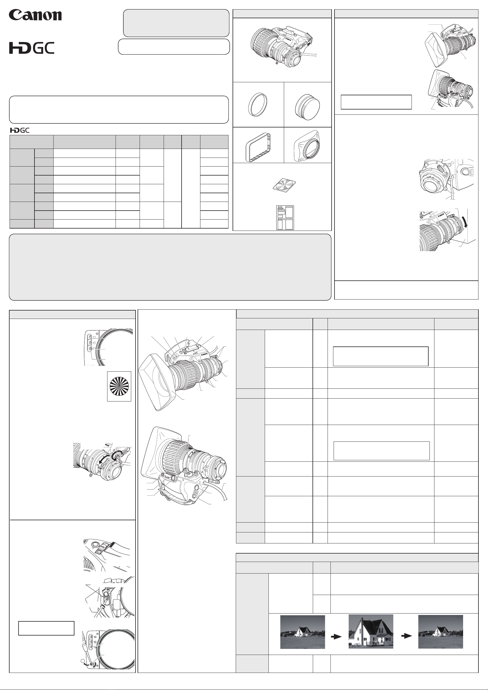
Multi-point focus shooting
(The focal point is
shifted from foreground
to background.)
④
⑨
②
Zoominbynormalfocusoperation.
Zoomouttoanearobjectbymacrooperation.
Zoominbynormalfocusoperation.
↓
Turn the zoom ring/lever ②from the widest angle
to telephoto.
VTR Recording ON/OFF ⑩Press the switch ⑩to start recording,
and press it again to stop.
RET Return video ⑪While switch ⑪held down, mian frame picture can be
seenintheviewnder.(Multiplecamerasystemused)
② Mount the lens on the camera
Before mounting the lens on the camera, make sure that the
camera’s power is turned off.
1.Positionthecamerahorizontally.
2.Turnthebayonetringofthecameracounterclockwiseas
viewed from the lens. Remove the dust cap from the camera
mount.
3. Remove the dust cap from the
lens.
4. Align the locating pin on the lens
mount with the slot on the camera
mount,andtthelensintothe
camera mount surface.
5.Turnthebayonetringclockwise
untilthelensmountisrmlyxed
in place.
6. Connect the power/iris control cable
connector on the back of the drive
unit to the appropriate receptacle
on the camera head.
*ForKTStypelenses
Connect an optional extension cable to the control cable of the
back side of the lens drive unit. Then connect the cable to the
connector on the optional remote controller.
OPERATION MANUAL Quick Guide
1 Check the Product List
①Mount the hood
on the lens
If the lens cap is attached, please
removethecaprst.
1. Fit the hood on the front of
the lens barrel.
2. Align the index marks.
3. Turn the hood lock knob clock-
wisetotightenthehoodsecurely.
Index Mark
Hood
Lens Barrel
MACRO
M
F.B
IRIS
AM
W
RET
T
KJ20x8.5BIKRSDA
20x
I.G.
Shtl
VTRэShtl
RETэShtl
ձ
ղ
ճ
մ
ON
ON
ON
ON
SPARE
VTR
MACRO
Locating Pin
Power/Iris
Control Cable
MACRO
M
F.B
A
W
T
Camera
③ Turn it on
Turn on the camera, and the power of the lens will be supplied.
④Back focus adjustment
1. Select an object at an approprate distance
(20x: 2 to 5 meters, 13x: 1 to 3 meters). A
siemens star chart is preferable.
2.Settheirisfullyopen.
3.Setthelenstothetelephotoendbyturning
the zoom ring.
4.Bringtheobjectintofocusbyturningthefocusring.
5.Setthelenstothewidestanglebyturningthezoomring.
6.Loosentheangeback
lock screw, and turn the
angebackadjustingring
to bring the object into
focus.
7. Repeat steps 3 to 6 a few
times until the object is
brought into focus at both the widest angle and telephoto.
8. After making sure that the object is in sharp focus, tighten
theangebacklockscrew.
P
IW
M
F.B
&
VTR
Shtl
Flange Back
Adjusting Ring
Flange back
Lock Screw
① Zoom Operation Change-over Knob
② Zoom Ring / Zoom Lever
③ Zoom Rocker Seesaw
④ Focus Ring
⑤ Iris Operation Mode Change-over Switch
⑥ Iris Ring
⑦ Instant Auto-Iris Switch
⑧ Connector for Remote Zoom Control
⑨ Macro Ring / Macro Button
⑩ VTR Switch
⑪RET Switch
⑫ Flange Back Lock Screw / Flange Back
Adjusting Ring
⑬ Iris Gain Adjusting Trimmer
⑭ Locating Pin
⑮ Power / Iris Control Cable
⑯ Hood
⑰ Hood Lock Knob
⑱ Shtl Button
⑲ Memo Switch
⑳ Dip Switch
3 Adjustment before Operation
① Read"GENERALSAFETYINFORMATION"(backside)beforeusingtheproduct.Thesafety
cautions must be observed.
② Read operation manual (this sheet and CD-ROM) before using the product. Keep the manual
in place for future reference.
BCTV Zoom Lens
NOTE
Set the zoom operation change-over knob ①to “MANU”
withoutfailbeforethisoperation.Failuretodosomay
result in malfunctioning.
NOTE
Set the iris operation change-over switch ⑤ to the “M”
withoutfailbeforethisoperation.Failuretodosomayresult
in malfunctioning.
Be sure to keep the caps in a safe
place so as not to lose them.
Hood
ZOOM
MANU.
SERVO
Hood Lock Knob
Present position Shuttle position Original position
Shtl
button is
held down
Shtl
button is
released
Max speed Max speed
For customers who purchased
KTS type lenses
For details of operation, see "Operations using a
remote controller" on back side.
IRIS GAIN
M
A
M
A
M
A
F
Z
I
Auto/Manual Iris
Selecting Switch
Auto/Manual Zoom
Selecting Switch
Auto/Manual Focus
Selecting Switch
Ifyourlensisremotecontroltype,
make sure to set the three auto/
manual selecting switches to "M"
position.
⑤Iris gain adjustment
1. Set the iris operation mode
change -over switch [for
KRSDandKRSDAtype]or
the auto/manual iris selecting
switch[forKTStype]to“A“
(auto).
2. Turn over/ remove the rubber
cap which is attached here.
3. Turn the iris gain adjusting
trimmer, using a small screw-
driver to set the level as de-
sired.
C.W.:highersensitivity
C.C.W.:lowersensitivity
4. After the iris gain adjust-
ment is completed, set it
based on the rubber cap
turned over. ,5,6*$,1
0
$
0
$
0
$
)
=
,
Iris Gain Adjusting
Trimmer
Auto/Manual Iris
Selecting Switch
Rubber
Cap
I.G.
Clockwise
Iris Gain Adjusting Trimmer
(KRSDandKRSDAtype)
(KTStype)
IRIS
A M
• •
T
W
Iris Operation Mode
Change-over Switch
P
IW
M
F.B
&
W
T
IRIS
RET
KJ20x8.5BKRSD PS12
20x
VTR
Shtl
Lenses
Lenses
SPECIFICATION (See PDF Operation Manual for details.)
Model Name Size (W × H × L)
Weight
(Without
Hood)
Focal
Length
Zoom
Ratio
Power
Source
Current
Consumption
(12V DC in)
KJ20x8.5B
KRSD A 163.3mm×103.0mm×170.4mm Approx.
1.27kg
8.5-170mm
20 x
DC12V
(DC10-
17V)
230 mA
KTS 113.7mm×91.4mm×170.4mm Approx.
1.41kg 435 mA
KH20x6.4
KRSD 163.3mm×103.0mm×182.5mm Approx.
1.27kg
6.4-128mm
230 mA
KTS 113.0mm×90.0mm×182.5mm Approx.
1.46kg 435 mA
KT20x5B
KRSD A 163.3mm×103.0mm×171.2mm Approx.
1.19kg 5-100mm
230 mA
KTS 113.0mm×90.0mm×171.25mm Approx.
1.33kg 435 mA
KJ13x6B
KRSD 165.4mm×105.1mm×211.7mm Approx.
1.59kg 6-78mm
13 x
230 mA
KTS 115.8mm×95.5mm×211.7mm Approx.
1.73kg 435 mA
KH13x4.5 KRSD 165.4mm×105.1mm×215.3mm Approx.
1.59kg 4.5-59mm 230 mA
Contact us
Canada: Canon Canada, Inc. Broadcast and Communications Div.
Tel:+1(905)863-8000 Fax:+1(905)863-8003
Mexico: Canon Mexicana, S. de R.L. de C.V. Call Center Div.
Tel:+52 55 5249 4905
USA : Canon U.S.A., Inc. ITCG METC
Tel:+1(800) 423-5367 (Toll Free) Fax:+1(201) 807-3344
Asia and Hong Kong, S.A.R. : Canon Hongkong Company Ltd.
ICP Marketing Div. Tel:+852-3191-2333
Korea : 캐논코리아 컨슈머 이미징 (주)제품마케팅팀 프로솔루션파트
대표전화 : (82)2-2191-8500 팩스 : (82)2-2191-8576
South and Southeast Asia : Canon Singapore Pte. Ltd.
REG ICP Sales & Marketing Div. Tel:+65-6799-8888
Europe/Africa/Middle East : Canon Europe Ltd. Broadcast Products Div.
Tel:+44(0)20-8588-8140 Fax:+44(0)20-8588-8929
Oceania: Canon Australia Pty. Ltd. CCI Div.
Tel:+61(0)2-9805-2000
Pleasecontactusifyouhavequestionsontheproducts.
KKJ20x8.5B KRSD A
KJ20x8.5B KTS
KH20x6.4 KRSD SY14
KJ13x6B KRSD
KJ13x6B KTS
KH13x4.5 KRSD SY14
KH20x6.4 KTS SX14A
KT20x5B KRSD A
KT20x5B KTS
MACRO
M
F.B
⑫
⑭
⑨
⑥
②
④
⑯
IRIS
AM
W
RET
T
KJ20x8.5BIKRSDA
20x
I.G.
Shtl
VTRэShtl
RETэShtl
ձ
ղ
ճ
մ
ON
ON
ON
ON
SPARE
⑬⑳ ⑦⑤③⑪
ZOOM
MANU.
SERVO
⑮
①
⑰
⑲
⑧⑩
⑱
2 Mount and Connect
For purchasing other accessories than shown right,
pleasecontactyourdealerorbelow.
4 Operation
5 Advanced Operation
Lensbody
Theshapeofthelensbodyandattachmentsare
differentbymodels.Thisillustrationisanexample
of KJ20x8.5B KRSD A.
Lens cap
KJ13x6B KTS, KJ13x6B
KRSD,KH20x6.4KTSonly
Dust cap
Hood cap Hood
Operation manual
•CD-ROM
•Quick Guide (this sheet)


 4.5/55 Operation manual")