Canon LV-S4 User manual

Multimedia Projector
SERVICE MANUAL
Original Version
FILE NO.
Model No. LV-S4

■Safety Instructions ................................................................................................3
■Specifications ........................................................................................................4
●Fuse ..........................................................................................................5
●Thermal switch ..........................................................................................5
●Lamp cover switch ....................................................................................5
■Circuit Protections ................................................................................................5
■Lamp Replacement ..............................................................................................7
■Mechanical Disassemblies....................................................................................8
●Electrical Parts Location ..........................................................................14
●Connection around the Main Board..........................................................15
■Optical Parts Disassemblies ..............................................................................16
■LCD Panel/Prism Ass’y Replacement ................................................................21
■Adjustments after Parts Replacement ................................................................22
■Optical Adjustments ............................................................................................23
■Electrical Adjustments ........................................................................................26
●Service Adjustment Menu Operation........................................................26
●Circuit Adjustments ..................................................................................27
●Service Adjustment Data Table ................................................................30
●Test Points and Locations ........................................................................34
■Chassis Block Diagrams ....................................................................................35
■Power Supply Lines ............................................................................................38
■Troubleshooting ..................................................................................................39
●No Power ..................................................................................................39
●No Picture ................................................................................................40
●No Sound..................................................................................................41
■Control Port Functions ........................................................................................42
■Waveforms ..........................................................................................................46
■Cleaning ..............................................................................................................47
■IC Block Diagrams ..............................................................................................48
-2-
■Contents
Drawings & Diagrams ................................................................ A1-A10
■Parts description and reading in schematic diagram ........................................ A2
■Schematic diagrams .................................................................................... A3-A6
■Printed wiring board diagrams .................................................................... A7-A8
■Pins description of ICs, transistors, diodes ...................................................... A9
- NOTE -
The different points between the previous model LV-S3 and the new model LV-S4 as follows;
- The electrical circuit (the LCD panels and the IN/OUT terminals)
- The lamp, lamp ballast and fan controls
- The optical parts
S-VIDEO IN
RGB IN
RGB IN
/
COMPONENT IN
COMPUTER /
COMPONENT
COMPONENT
AUDIO IN
VIDEO IN SERVICE PORT
RESET
AUDIO
IN
COMPUTER/ S-VIDEO/
COMPUTER/ S-VIDEO/
COMPONENT IN
COMPONENT IN
AUDIO IN
VIDEO SERVICE PORT
RESET
AUDIO OUT
(VARIABLE)
MONITOR OUT
MONITOR OUT
LV-S3 LV-S4

-3-
■Safety Instructions
WARNING:
The chassis of this projector is isolated (COLD) from AC line by using the converter transformer. Primary side of
the converter and lamp power supply unit circuit is connected to the AC line and it is hot, which hot circuit is iden-
tified with the line ( ) in the schematic diagram. For continued product safety and protection of personnel
injury, servicing should be made with qualified personnel.
The following precautions must be observed.
SAFETY PRECAUTIONS
1: An isolation transformer should be connected in the
power line between the projector and the AC line
before any service is performed on the projector.
2: Comply with all caution and safety-related notes pro-
vided on the cabinet back, cabinet bottom, inside the
cabinet or on the chassis.
3: When replacing a chassis in the cabinet, always be
certain that all the protective devices are installed
properly, such as, control knobs, adjustment covers
or shields, barriers, etc.
DO NOT OPERATE THIS PROJECTOR WITHOUT
THE PROTECTIVE SHIELD IN POSITION AND
PROPERLY SECURED.
4: Before replacing the cabinet cover, thoroughly
inspect the inside of the cabinet to see that no stray
parts or tools have been left inside.
Before returning any projector to the customer, the
service personnel must be sure it is completely safe to
operate without danger of electric shock.
SERVICE PERSONNEL WARNING
Eye damage may result from directly viewing the light produced by the Lamp used in this equipment. Always turn
off Lamp before opening cover. The Ultraviolet radiation eye protection required during this servicing.
Never turn the power on without the lamp to avoid electric-shock or damage of the devices since the stabilizer
generates high voltages(15kV - 20kV) at its starts.
Since the lamp is very high temperature during units operation replacement of the lamp should be done at least
45 minutes after the power has been turned off, to allow the lamp cool-off.
PRODUCT SAFETY NOTICE
Product safety should be considered when a component replacement is made in any area of the projector.
Components indicated by mark in the parts list and the schematic diagram designate components in which
safety can be of special significance. It is, therefore, particularly recommended that the replacement of there parts
must be made by exactly the same parts.

-4-
■Specifications
This symbol on the nameplate means the product is Listed by Underwriters
Laboratories Inc. It is designed and manufactured to meet rigid U.L. safety stan-
dards against risk of fire, casualty and electrical hazards.
The CE Mark is a Directive conformity mark of the European Community (EC).
Mechanical Information
Projector Type Multi-media Projector
Dimensions (W x H x D) 10.63" x 3.27" x 7.76" (270mm x 83.1mm x 197.2mm) (not including Adjustable Feet)
Net Weight 5.1lbs (2.3 kg)
Feet Adjustment 0˚ to 8.0˚
Panel Resolution
LCD Panel System 0.5" TFT Active Matrix type, 3 panels
Panel Resolution 800 x 600 dots
Number of Pixels 1,440,000 (800 x 600 x 3 panels)
Signal Compatibility
Color System
PAL, SECAM, NTSC, NTSC4.43, PAL-M, PAL-N
High Definition TV Signal
480i, 480p, 575i, 575p, 720p, 1035i, and 1080i
Scanning Frequency
H-sync. 15 ~ 80 KHz, V-sync. 50 ~ 100 Hz
Optical Information
Projection Image Size (Diagonal) Adjustable from 34" to 200"
Projection Lens F 1.6 ~ 1.8 lens with f 18.3 mm ~ 21.9 mm with manual zoom and focus
Throw Distance 4.3' ~ 21.3' (1.3m ~ 6.5m)
Projection Lamp 160W UHP Lamp
Interface
Video Input Jack RCA Type x 1
Audio Input Jack Mini Jack (Stereo) x 1
Monitor Out Terminal (VGA) HDB15 Terminal X 1
Computer / S-Video / Component Input Terminal
(VGA) HDB15 Terminal X 1
Service Port Connector Mini DIN 8 pin x 1
Audio Output Jack Mini Jack (stereo) x 1 (Variable)
Audio
Internal Audio Amp 0.8 W RMS
Built-in Speaker 1 speaker, ø1.3" (32mm)
Power
Voltage and Power Consumption AC 100 ~ 120 V (3.6 A Max. Ampere), 50 / 60 Hz (The U.S.A and Canada)
AC 200 ~ 240 V (1.8 A Max. Ampere), 50 / 60 Hz (Continental Europe)
Operating Environment
Operating Temperature 41 ˚F ~ 95 ˚F (5 ˚C ~ 35 ˚C)
Storage Temperature 14 ˚F ~ 140 ˚F (-10˚C ~ 60 ˚C)
Remote Control Unit
Battery AAA, SUM-04 or LR03 type x 2
Operating Range 16.4’ (5m) / ±30˚
Dimensions 2.0”(W) x 0.91”(H) x 4.8”(D) (51.5mm x 23.2mm x 123mm)
Net Weight 2.11 oz (60 g) (including batteries)
* Following information differs from the model LV-S3 ;
- the mechanical and electrical specifications

-5-
■Circuit Protections
●Lamp cover switch
The lamp cover switch (SW8801) cuts off the drive signal to the
lamp circuit when the lamp cover is removed or no close com-
pletely. After opening the lamp cover for replacing the lamp ass’y,
place the lamp cover correctly otherwise the projector can not
turn on.
●Thermal switch
There is the thermal switch (SW902) inside of the projector to
prevent the internal temperature rising abnormally. When the
internal temperature reaches near 100˚C, turn off the AC main
power supply automatically.
The thermal switch is not reset to normal automatically even if the
internal temperature becomes normal. Reset the thermal switch
following procedure.
Check the resistance between terminals of thermal switch by
using the tester. If it has high impedance, thermal switch may be
in operative.
How to reset the thermal switch
1. Remove the cabinet top following to “Mechanical
Disassemblies”.
2. Press the reset button on the thermal switch with a sharp-
pointed tool.
CAUTION:
Before press the reset button, make sure that the AC cord must
be disconnected from the AC outlet.
This projector provides the following circuit protections to operate in safety. If the abnormality occurs inside the pro-
jector, it will automatically turn off by operating one of the following protection circuits.
●Fuse
A fuse is located inside of the projector. When the POWER indica-
tor is not lightning, the fuse may be opened. Check the fuse as fol-
lowing steps.
The fuse should be used with the following type;
How to replace the fuse
1. Remove the cabinet top following to “Mechanical
Disassemblies”.
2. Remove the cover on the Filter Board.
3. Remove fuse from fuse holder.
To install the fuse, take reversed step in the above.
Fuse Part No.: 423 022 2102
TYPE T4.0AH 250V FUSE
LITTEL FUSE INC. TYPE 215004
Fuse
Filter Board
Lamp Cover
Lamp Cover Switch
Thermal Switch
* Following information differs from the model LV-S3 ;
- the cabinet

-6-
●Warning temperature and power failure protection
The WARNING indicator flashes red and the projector will automatically turn off when the internal temperature of
the projector exceeds the normal temperature or when stopping cooling fans or when the internal power supply
lines are failed.
Check the following possible causes and wait until stopping the WARNING indicator flashing.
Possible causes
- Air filter is clogged with dust particles. Remove dust from the air filter by following instructions in the “Air filter
care and cleaning” below.
- Ventilation slots of the projector are blocked. In such an event, reposition the projector so that ventilation slots are
not obstructed.
- Check if projector is used at higher temperature place (Normal operating temperature is 5 to 35 ˚C or 41 to 95˚F)
If the WARNING indicator still continues to flash, there may be defects on cooling fans or power supply circuits.
Please check fan operation and power supply lines referring to the “Power Supply Lines Chart”.
Air filter care and cleaning
The removable air filter prevents dust from accumulation on the surface of the projection lens and projection mirror.
Should the air filters become clogged with dust particles, it will reduce the cooling fan’s effectiveness and may
result in internal heat build up and adversely affect the life of the projector.
To clean up the air filters, follow the cleaning procedure
below:
1. Turn off the projector, and disconnect the AC power
cord from the AC outlet.
2. Turn the projector upside down and remove the air fil-
ters by pulling the latches upward.
3. Clean the air filters with a brush or rinse them softly.
4. When cleaning the air filters by rinsing, dry them well.
Replace the air filters properly. Make sure that the air fil-
ters are fully inserted.
CAUTION:
Do not operate the projector with the air filters removed.
Dust may accumulate on the LCD panel and the projection
mirror degrading picture quality.
Do not put the small parts into the air intake vents. It may
result in the malfunction of the projector.
RECOMMENDATION
We recommend avoiding dusty/smoky environments when
operating the projector. Use of the projector in these envi-
ronments may cause poor image quality.
When using the projector under dusty or smoky conditions,
dust may accumulate on a lens, LCD panels, or optical ele-
ments inside the projector. The condition may degrade the
quality of a projected image.
When the symptoms above are noticed, please clean up
the LCD panel and lens following to the “Cleaning
Method”.
Air filters
Circuit Protections * Following information differs from the model LV-S3 ;
- the cabinet, the air filter 3pcs. --> 4 pcs.
NOTE:
When inserting the side air filter,
make sure that the dented part
of the filter is outside.

-7-
WARNING:
- Allow a projector to cool, for at least 45 minutes before you open Lamp
Cover. The inside of a projector can become very hot.
- For continued safety, replace with a lamp assembly of the same type.
- Do not drop a lamp assembly or touch a glass bulb! The glass can
shatter and may cause injury.
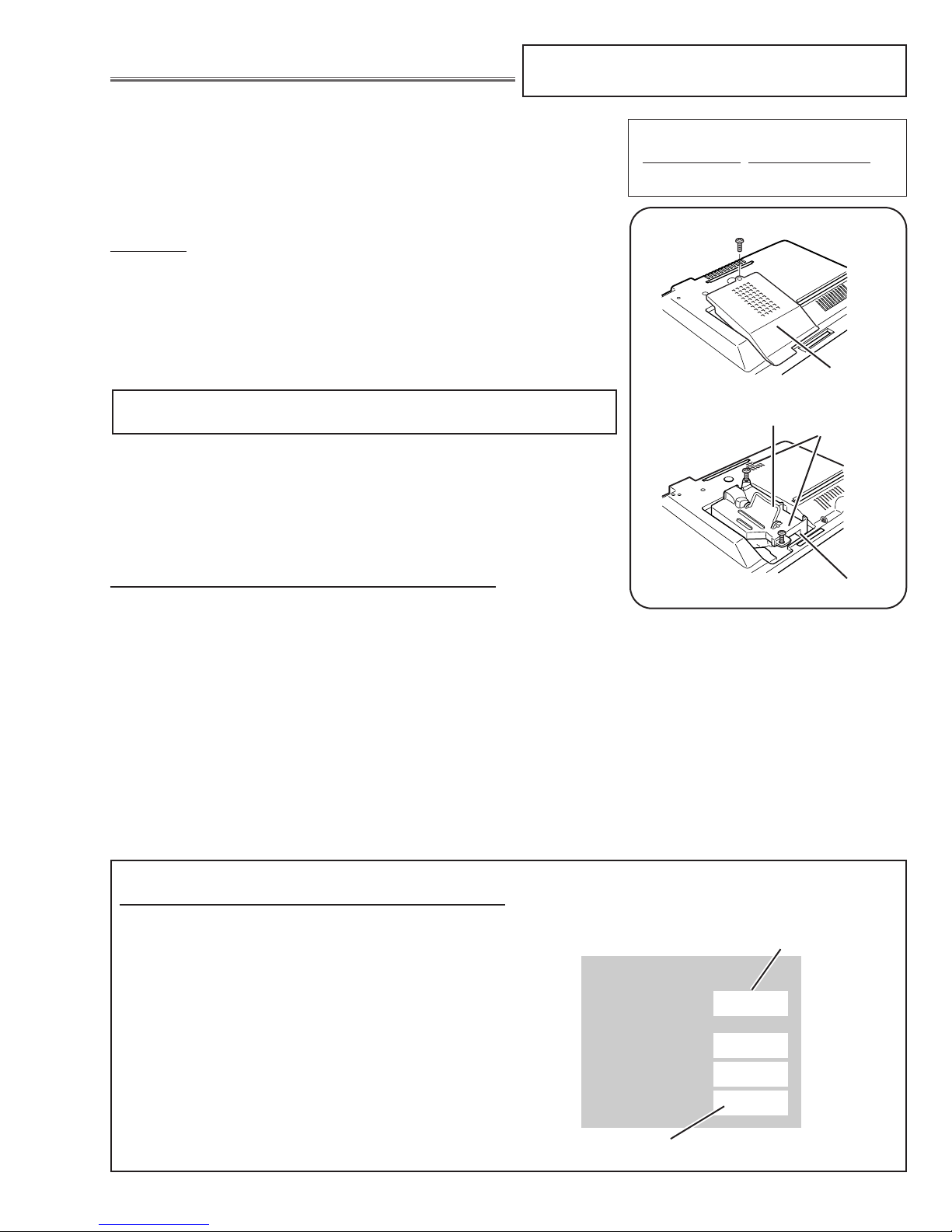
Procedure
1Turn off the projector and disconnect the AC plug. Allow the projector to
cool at least for 45 minutes.
2Remove 1 screw and remove the lamp cover.
3Loosen 2 screws and pull out the lamp assembly by grasping the handle.
4Replace the lamp assembly securely and tighten 2 screws.
5Close the lamp cover and tighten 1 screw.
6Connect the AC Power Cord to the projector and turn on the projector.
Note:
- Do not reset the Lamp Replace Counter, except after lamp is replaced.
- The projector can not be turned-on with lamp cover removed, because
when the lamp cover is removed, the lamp cover switch is also released
to switch off the mains power for safety.
7Reset the Lamp Replace Counter, see below explanation.
■Lamp Replacement
1Turn the projector on, press the MENU button and the
On-Screen Menu will appear. Press the POINT
LEFT/RIGHT buttons to move the red frame pointer to
the Setting Menu icon.
2Press the POINT DOWN button to move the red
frame pointer to the Lamp counter reset item and then
press the OK button. The message “Lamp replace
counter reset?” is displayed. Move the pointer to [Yes]
and then press the OK button.
3Another confirmation dialog box appears and select
[Yes] to reset Lamp Replace Counter .
Please refer to the owners manual for further informa-
tion.
Recommendation
Should the air filter become clogged with dust particles,
it will reduce the cooling fan’s effectiveness and may
result in internal heat build up and short lamp life. We
recommend cleaning the air filter after the projection
lamp is replaced.
Refer to “Air Filter Cleaning”.
The LAMP REPLACE indicator will light yellow when
the total lamp used time reaches 2,500 hours. This is
to indicate that lamp replacement is required.
The total lamp used time is calculated by using the
below expression;
Total lamp used time = Teco + Tnormal(1+1/4)
Teco :used time in the Silent mode
Tnormal :used time in the Normal and Auto mode
You can check the lamp replace counter following to
below procedure.
1Press and hold the POWER button on the projector or
the remote control unit for more than 20 seconds.
2 The projector used time and lamp used time will be
displayed on the screen briefly.
Lamp cover
Counter
Projector
Lamp
Normal
Eco
Total
130H
24H
100H
130H
Total lamp used time
ORDER REPLACEMENT LAMP
Type No.Service Parts No.
LV-LP23 610 317 7038
How to reset Lamp Replace Counter
How to check Lamp used time
Screws
Handle
Lamp Assembly
Screw
Projector used time
* Following information differs from the model LV-S3;
- the replacement lamp number, SET --> OK button.

-8-
1Remove the Air Filter in the side of the set at first.
(If not, the filter would be broken.)
2Remove 2 screws A(M3x6) and 3 screws B(M3x8),
and then take the Cabinet Top upward off.
■Mechanical Disassemblies
Mechanical disassemble should be made following procedures in numerical order.
Following steps show the basic procedures, therefore unnecessary step may be ignored.
Caution:
The parts and screws should be placed exactly the same position as the original otherwise it may cause loss of
performance and product safety.
Fig.1
Cabinet Top removal
1
Screws Expression
(Type Diameter x Length) mm
T type M Type
B
B
A
B
A
Air filter (Panel net_side)
Cabinet Top
AT FIRST, REMOVE THE AIR FILTER.
* Following information differs from the model LV-S3 ;
- the new cabinet and mechanical disassemblies

-9-
Mechanical Disassemblies
1Remove 4 screws (M3x6) to take the Main Board upward.
Fig.3
Main Board removal
3
Main Board
Fig.2
C
A
A
B
B
R/C Board
Cabinet Front
Speaker
(SP901)
D
D
1Remove 2 screws A(M3x6) and 2 screws B(M3x6) to
take the Cabinet Front off.
2Remove 1 screw C (T3x6) to the R/C Board on the
Cabinet Front.
3Remove 2 screws D(T3x6) to take the Speaker (SP901)
off.
Cabinet Front, R/C Board and Speaker
removal
2
NOTE :
About the connection around the Main Board, refer to Page 15.

-10-
Mechanical Disassemblies
1Remove 1 screw (M3x6) to take the Thermal Switch
(SW902) and the Cover Spacer off.
Fig.5
Thermal SW removal
5
Thermal SW
Lamp Cover Spacer
Fig.4
1Take the Rear Panel ass’y upward off and remove 1
screw A (M4x4) .
2Remove 2 screws B(T3x8) to take the fan (FN903) off.
3Remove 4 screws C(T3x8) and take AV Board from the
Rear Panel ass’y off.
Rear Panel, AV Board and FN903 removal
4
A
B
C
B
CC
C
AV Board
Rear Panel
FN903
Thermal SW Cover-A
Thermal SW Cover-B

-11-
Mechanical Disassemblies
1Remove 4 screws A (T2x4) to take off the spacer sheet
and the shield plate on the Power Board.
2Remove 1 screw B (M3x8), 2 screws C (T3x8) and 1
screw D(M4x4) to take the Power Unit and the Fan
(FN901) off.
3Take the Fan(FN901) from the Holder by pulling it.
4Remove 3 screws E (T3x6) to take the Power Unit off.
Notes:
You can remove the connectors on the Power Unit
after the Lamp Ballast Unit removal.
Fig.7
Power Unit and FN901 removal
7
A
A
A
A
B
E
E
E
D
C
Spacer Sheet
Power Board
FN901
Holder
Fig.6
1Remove 2 screws A (M3x10) and take the Lamp Cable
off.
2Remove 6 screws B (T3x10) and take the Optical Unit
upward off.
Optical Unit removal
6
AA
B
B
B
B
B
B
Optical Unit
Lamp Cable
Shield Plate
C

-12-
Mechanical Disassemblies
1Remove 2 screws A(T3x8) to take the Fan (FN906)
ass'y off.
2Remove 2 screws B(M3x30) to take the Fan (FN906)
off from the Fan mounting base.
Fig.9
FN906 removal
9
AA
BB
FN906 Ass'y
FN906
Fig.8
1Remove 1 screw A (M4x4) to take the Earth cable off.
2Remove 2 screws B (T3x8) to take the Lamp Ballast
Unit and the Filter Board off.
3Remove 2 screws C (T3x6) to take the Lamp Ballast
Unit off.
4Remove 3 screws D (T3x6) to take the Filter Board off.
Lamp Ballast Unit and Filter Board
removal
8
A
B
B
C
C
D
D
D
Lamp ballast Board
Holder
Filter Board
Spacer Sheet
Spacer Sheet
Shield Plate

-13-
1Remove 1 screws A(T4x4 + washer) to take the shield
plate off.
2Remove 2 screws B(T3x8) to take the Fan (FN904) and
the duct off.
3Remove 2 screws C (T3x8) to take the SW Board off.
Mechanical Disassemblies
Fig.11
FN904 and Lamp Cover SW removal
11
FN904
SW Board
Earth Plate
Duct
B
B
C
C
1Remove 1 screw A (T3x8) to take the Duct under the
Panel.
2Remove 1 screw B(T3x8) to take the Holder with the
Fans(FN902 and FN905) off.
3Remove 2 screws C(T3x10) to take the Fans (FN902
and FN905) off.
4Remove 1 screw D(T3x8) to take the Sensor Board off.
Fig.10
FN902, FN905 and Sensor Board removal
10
A
B
C
C
DSensor Board
FN902
FN905
Shield Plate
A
Spacer sheet
Spacer

-14-
Mechanical Disassemblies
●CIRCUIT BOARD
●OUT OF CIRCUIT BOARD
Thermal Switch
(SW902)
FN904
Intake Fan
FN903
Exhaust Fan
A/V Board
Main Board
FN902
Intake Fan
FN905
Intake Fan
FN906
Exhaust Fan
FN901
Intake Fan
Filter Board
Unit_Lamp Ballast
Unit_Power
Sensor Board
R/C-A Board
Control Board
Switch Board
Speaker
(SP901)
Optical Lamp
(LP900)
Electrical Parts Location
* Following information differs from the model LV-S3 ;
- the cabinet, the control board

-15-
Mechanical Disassemblies
K66E K66C
K48K
PART SIDE
K8G
1AA4B10C4340A
K8A
K25G
K8F
K25B
K25R
K8E K66A K66B K8H
RED BLUE
RED
POWER
"CN202"
FN904
LAMP BALLAST
"CN300"
FN903
FN905FN902
R/C-A
"K68D"
SENSOR
"K88A"
CONTROL
"K68B"
K66F K66DK48L K8B
K50A
K50B
SOLDER_SIDE
BLUE
RED
RED
POWER
"CN201"
FN906
SW"K8811"
FN901
MAIN
(SIDE: A)
MAIN
(SIDE: B) NOTE :
The connector (BLUE) from FN904 should be connected to K66C (WHITE).
The connector (WHITE) from FN906 should be connected to K66D (BLUE).
Connection around the Main Board
* Following information differs from the model LV-S3 ;
- the connection of FN904 and FN906

■Optical Parts Disassemblies
Before taking this procedure, remove Cabinet Top, Main Board and Optical Unit following to the “Mechanical
Disassemblies”.
-16-
Fig.2
Fig.1
1Remove 2 screws to take the Lamp Holder off.
Lamp Holder removal
1
1Remove 3 screws to take the Projection Lens ass'y off.
Projection Lens Ass'y removal
2
Optical Unit Box
Lamp Holder
Optical Unit Box
Projection Lens
and Panel/Prism Ass'y
* Following information differs from the model LV-S3 ;
- the lamp holder removal

-17-
Fig.4
Fig.3-1
1Remove each screw to take the polarized glass-in R/G/B
off.
Note:
The polarized glass-in_red is sticked on the condenser
lens_red. So, it cannot be removed separately.
Polarized Glass-In removal
3
1Remove 6 screws to take the Optical unit top off.
Optical Unit Top removal
4
Optical Unit Box
Optical Unit Base
Polarized glass_Red Polarized glass
_Green and Blue
Polarized glass sticked
on Condenser lens(R)
Polarized glass with
mounting holder
Fig.3-2
RB
G
Screw
Polarized glass_Red
Polarized glass_Blue
Polarized glass_Green
Screw
Screw
Optical Parts Disassemblies

-18-
Optical Parts Disassemblies
1Remove 3 screws A(M2x4) and take the Condenser lens ass'y downward off.
2Remove 2 screws B(M2x4) and take the Relay lens ass'y downward off.
AA
A
BB
Relay lens ass’y
Condenser lens ass’y
Condenser lens Ass'y and Relay lens Ass'y removal
5
* Following information differs from the model LV-S3 ;
- the optical disassemblies on page 18 - 19

-19-
Optical Parts Disassemblies
Rugged surface side come this side.
(Integrator lens)
Film attached side comes this side.
(Prism (PBS))
Marker comes this side.
The printed marker side come this surface
side and top side. (Dichroic mirror)
LCD panel
LCD panel
LCD panel
Glass should be placed as the film
attached side comes LCD panel side.
Film attached side
Film attached sideFilm attached side
Polarized glass
Plate
Polarized glass
Condenser lens (R)
Plate and Polarized glass are not overlapping.
Printed marker comes
top side.
(Condenser lens)
The printed marker comes this side.

-20-
Optical Parts Disassemblies
14
Fig.6
3
1
2
4
9
13
6
10
15
11
17
16
5789
1Integrator lens (IN)
2Mirror (W)
3Integrator lens (OUT)
4PBS (polarizing beam splitter)
5Condenser lens (OUT)
6Dichroic mirror (B)
7Dichroic mirror (G)
8Relay lens (IN)
9Mirror (R)
10 Relay lens (OUT)
11 Assy, Condenser lens (R)
12 Condenser lens (G)
13 Condenser lens (B)
14 Mirror (B)
15 Polarized glass (IN/G)
16 Polarized glass (IN/B)
17 Assy, LCD PNL / Prism
Key No. Description
12
* Following information differs from the model LV-S3 ;
- added items No.15 - 17
When the optical parts in the optical unit mounting or assembling, the
parts must be mounted in the specified location and direction as
shown in figure below.
Locations and Directions
Other manuals for LV-S4
2
Table of contents
Other Canon Projector manuals

Canon
Canon LV-X1 User manual

Canon
Canon MARKLL WUX10 Installation manual

Canon
Canon RE-450X User manual

Canon
Canon 1318C002 User manual

Canon
Canon LV-X1J User manual

Canon
Canon XEED WUX10 User manual

Canon
Canon LX-MU500Z User manual

Canon
Canon 2105B002AA User manual

Canon
Canon LV-HD420 User manual

Canon
Canon LV-X2 User manual

Canon
Canon 4K501ST User manual

Canon
Canon LV-7565F User manual

Canon
Canon LV-S1 User manual

Canon
Canon LV-7392A Installation manual

Canon
Canon LE-5W User manual

Canon
Canon REALiS WUX5000 User manual

Canon
Canon T2000 User manual

Canon
Canon LV-7292S User manual

Canon
Canon LV-X310ST User manual

Canon
Canon LV-7575 User manual