Caple TSCHB3 User manual

Page 1 TSCH Slide-out Extractors.doc
INSTALLATION AND OPERATING
INSTRUCTION BOOKLET
TSCHB3
TELESCOPIC EXTRACTOR
IMPORTANT: You must read this instruction Book before
installing or using this appliance and retain it for future use.
Caple Products
Telephone 0870 2411142
Facsimile 0117 982 6878

Page 2 TSCH Slide-out Extractors.doc
YOUR NEW COOKER HOOD
Dear Customer
These instructions are designed to help you get to know your new cooker hood
quickly and to achieve the best possible results.
It is most important that this instruction book should be retained with the
appliance for future reference. Should the appliance be sold or transferred to
another owner, or should you move house and leave the appliance, always
ensure that the book is supplied with the appliance in order that the new owner
can be acquainted with the functioning of the appliance and the relevant
warnings. Please ensure that you have read the whole instruction book before
using the appliance and that you follow the recommendations given.
The author and publisher have used their best efforts in preparing this book. The Maurice Lay Group
and the author make no representation or warranties with respect to the accuracy or completeness of
the contents of this book. The information in this book is subject to change without notice.
SAFETY WARNINGS
These warnings are provided in the interests of safety. Ensure you read and
understand them all before installing or using this appliance.
INSTALLER
•A qualified electrician or competent
person must undertake any installation
work.
•This cooker hood must be installed in
accordance with the installation
instructions and all requirements must
be adhered to.
•If the cooker hood is installed for use
above a gas appliance then the
provision for ventilation must be in
accordance with the Gas Safety Codes
of Practice BS.6172, BS.5440 and
BS.6891 (Natural Gas) and BS.5482
(LP Gas) 1994, the Gas Safety
(Installation & Use) Regulations, the
Building Regulations issued by the
Department of the Environment.
•The fan motor of this cooker hood
incorporates a cut-out device, which
will operate if the cooker hood is
installed below the minimum heights
recommended in this booklet, or if the
fan motor becomes overheated. If the
cut-out device is activated, switch off
the fan motor and allow the cooker
hood to cool. The cut-out device will
reset itself when the fan motor has
cooled sufficiently.
•It is dangerous to alter the
specifications or modify this product in
anyway.
•When installed between adjoining wall
cabinets the wall cabinets must not
overhang the hob.
•If the room where the cooker hood is
to be used contains a fuel-burning
appliance such as a central heating
boiler then its flue must be of the
room sealed or balanced flue type.
•If other types of flue or appliance are
fitted ensure that there is an adequate
supply of air to the room.
•When the cooker hood is used in
conjunction with appliances supplied
with energy other than electricity, the
negative pressure in the room must
not exceed 0.4mbar to prevent fumes
being drawn back into the room by the
hood.
•The ducting system for this appliance
must not be connected to any existing
ventilation system, which is being used
for any other purpose.
•Do not install above a cooker with a
high level grill.

Page 3 TSCH Slide-out Extractors.doc
USER
•This cooker hood is designed to be
operated by adults. Children should
not be allowed to tamper with the
controls or play with the appliance.
•This product is for domestic use only.
•Never leave frying pans unattended as
overheated oils and fats might catch
fire.
•Never do flambé cooking under this
cooker hood.
•Do not leave naked flames under this
hood.
•This cooker hood could be a fire
hazard if the grease filter and charcoal
filters are not replaced as
recommended.
TECHNICAL INFORMATION
It is dangerous to alter the
specification or attempt to modify
this cooker hood in any way.
DIMENSIONS
Height 175mm
Width 598 mm
Depth 280mm
Ducting Spigot dia. 100mm
Weight - Gross 7.0kg
Weight - Net 6.0kg
POWER CONSUMPTION
Total 175W
Fan 135W
Lamp 40W
PERFORMANCE TABLE
Speed 1 2
Capacity m3/h 150 240
Capacity It/sec 42 67
Pressure H20 19 22
Input W 85 135
Noise Level dBA 50 58
INSTALLATION INSTRUCTIONS
ELECTRICAL CONNECTIONS
WARNING: DOUBLE INSULATED DO
NOT EARTH
ELECTRICAL REQUIREMENTS
Any permanent electrical installation must
comply with the latest I.E.E. Regulations
and local Electricity Company regulations.
For your own safety this should be
undertaken by a qualified electrician e.g.
your local Electricity Company, or a
contractor who is on the role of the
National Inspection Council for Electrical
Installation Contracting (NICEIC).
ELECTRICAL CONNECTION
Before connecting to the mains supply
ensure that the mains voltage corresponds
to the voltage on the rating plate inside
the cooker hood.
This appliance is fitted with a 2-core
mains cable and must be permanently
connected to the electricity supply via a
double-pole switch having 3mm minimum
contact gap on each pole. A Switch Fuse
Connection Unit to BS.1361 Part 4, fitted
with a 3A fuse is a recommended mains
supply connection accessory to ensure
compliance with the Safety Requirements
applicable to fixed wiring instructions.
This appliance conforms to BS.800: 1988 and EEC Directive 78:308 regarding
suppression of radio and television.
NOTE: CE Marking certifies that this appliance complies with the requirements
laid down in EEC Directive 89:336 (Electromagnetic Compatibility and
subsequent modifications; EEC Directive 73/23 (Low Voltage) and any
subsequent modifications.

Page 4 TSCH Slide-out Extractors.doc
INSTALLATION INSTRUCTIONS
INSTALLATION REQUIREMENTS
Please ensure that when the appliance is
installed it is easily accessible to an
engineer in the event of a breakdown.
All installations must comply with the local
authorities requirements for the discharge
of exhaust air.
Incorrect installation may affect the safety
of this cooker hood.
IMPORTANT: Before installation
check the wall to which the cooker
hood is to be fitted for electric
cables, water pipes or gas pipes
before drilling.
If it is necessary to fix the cooker hood to
a hollow construction plaster or partition
board structure then it must be sufficiently
reinforced to be quite rigid in the area of
the hood mounting brackets and special
screws and Rawlplugs may be required
which are suitable for hollow plaster or
partition board walls.
The installation work must be undertaken
by a qualified and competent person. The
manufacturer disclaims any responsibility
for damages due to incorrect installation
of the cooker hood or if the cooker hood
is not installed in compliance with the
relevant regulations controlling this type
of installation.
UNPACKING
Before unpacking the cooker hood
position the carton with the arrows
pointing upwards as illustrated on the
carton. Care should be taken when
unpacking the cooker hood to ensure that
the items supplied below are not thrown
away with the box.
1 No. Template
6 No. Fixing screws
1 No. 100mm dia. ducting spigot
CLEARANCE HEIGHTS
The cooker hood is designed to be fitted
over a cooking appliance at the clearance
heights stated, provided the maximum
output of the hob beneath does not
exceed 7kw for electric and 10kw for gas.
If the output of the appliance below the
cooker hood exceeds the maximum
outputs quoted, please refer to the cooker
manufacturer's installation instructions.
A minimum height of 650mm is required
when installed above an electric hob, or
700mm when installed above a built-in
gas hob.
When installed between adjoining wall
cabinets, the wall cabinets must not
overhang the hob and the distance
between the underside of the cabinet and
the worktop must be 450mm. If the
height of the wall cabinet is less than
450mm a gap of 50mm must be
maintained either side of the hob.
Do not install above a cooker with a
high level grill.
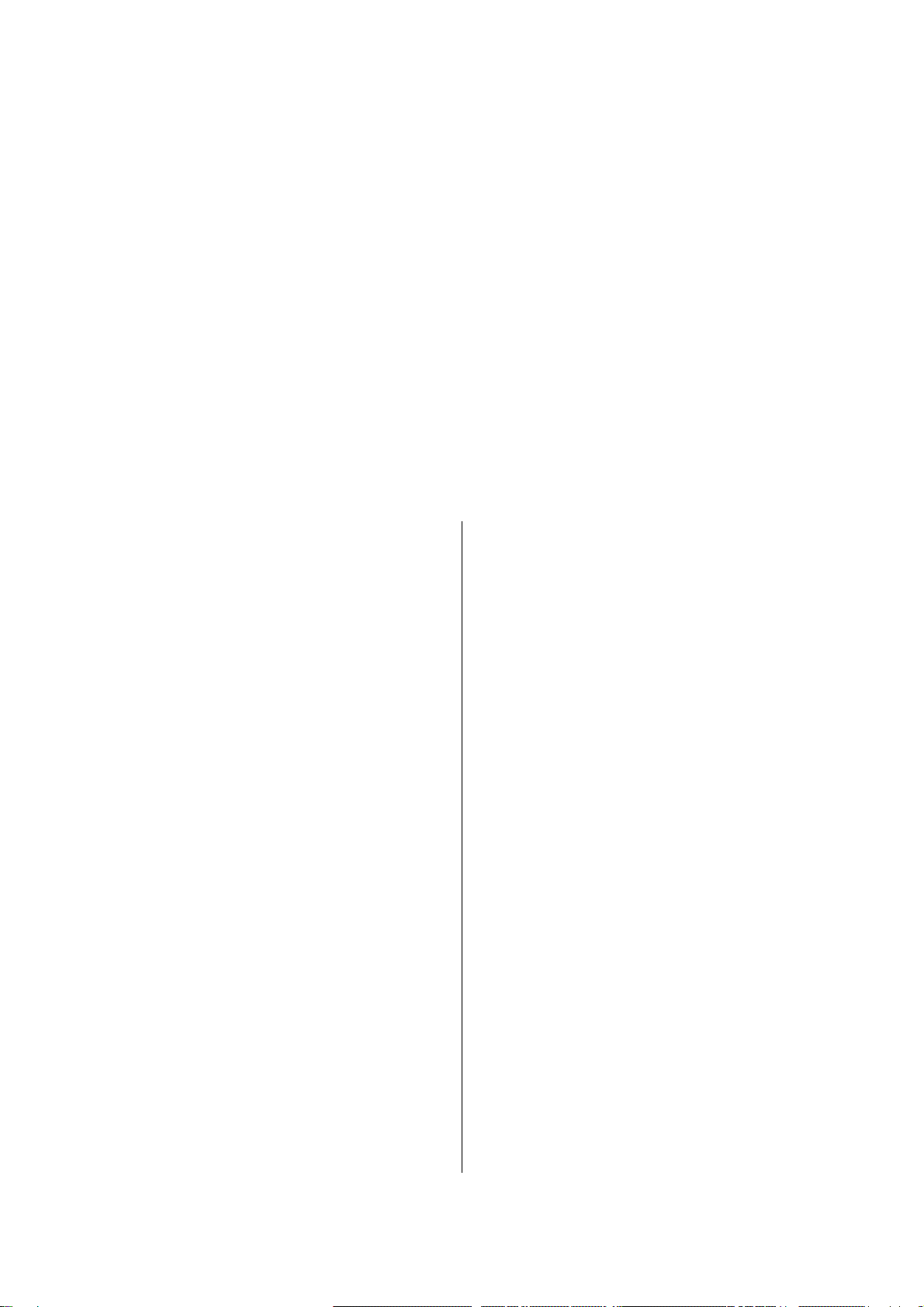
FITTING INTO A WALL CABINET
To fit the cooker hood into the wall
cabinet, use the paper template provided
to mark the hole position on the underside
of the cabinet. When fitted the trim rail
along the front of the cooker hood must
align with the front of the cabinet door.
It is important to check the hole is
positioned correctly using a tape
measure before cutting the hole and
no metal fastenings obstruct the
cut-out.
Cut the hole in the base of the cabinet
using a pad saw or jig saw. Open the
metal grease filter tray and remove it.
Raise the hood into the cut-out ready for
fixing. Pilot drill the holes for the fixing
screws from inside the hood and fix the
hood using the screws in the bag of
fittings provided.

Page 5 TSCH Slide-out Extractors.doc
FITTING THE SPACER
After fitting the hood into the wall cabinet,
the spacer provided should be fitted on
the underside of the hood, at the rear to
close off the space between the hood and
wall. The spacer can be adjusted from a
minimum of 1mm to a maximum of
30mm.
EXTRACTION
The cooker hood is supplied in the
extraction mode. In the extraction mode
contaminated air enters the cooker hood,
passes through the grease filter and out
through ducting to the atmosphere.
The cooker hood is more effective when
used in the extraction mode.
DUCTING
The preferred ducting should be rigid fire
retardant and must be 100mm in
diameter. Flexible ducting should only be
used for short runs or as an accessory.
Flexible ducting should not be turned
through very tight bends as this may
impair the performance of the cooker
hood.
The length of ducting should be no more
than:
3 meters with one 90° bend
2 meters with two 90° bends
Bends of more than 90° will reduce the
efficiency of the cooker hood and reduce
the airflow.
RECIRCULATION
The cooker hood is supplied suitable for
use in the extraction mode, without the
(optional) charcoal filter fitted.
In the recirculation mode contaminated air
enters the cooker hood, passes through
the grease filter and cleansing charcoal
filter and back out into the kitchen
through a duct in the top of the kitchen
cabinet.
When installed in the recirculation mode it
will be necessary for the installer to
fabricate a chimney from the ducting
spigot on the top of the cooker hood to a
terminal grille in the top of the kitchen
cabinet.
FITTING THE CHARCOAL FILTER
Open the metal grease filter tray and
remove it. Place the charcoal filter Fig. B
over the fan cover Fig. A while holding the
filter securely and insert the disk Fig. C,
turning the disk clockwise.
The TSCHB3 and TSCHW3 hood
require one CAP10CF charcoal filter.

Page 6 TSCH Slide-out Extractors.doc
OPERATING INSTRUCTIONS
CONTROLS
The cooker hood functions are controlled
by an automatic microswitch and a slider
switch.
ELECTRICAL CONNECTION
Ensure the cooker hood is switched `ON'
at the supply connection unit.
AUTOMATIC MICROSWITCH
The `automatic microswitch' is activated
by the movement of the telescopic
mechanism and switches the worktop
lighting and fan motor ON when opened
and OFF when closed.
FAN SWITCH
The switch marked with the 'fan symbol'
at the front of the hood controls the fan
speeds.
Position-1should be selected when
simmering and using up to
four pans.
Position-2should be selected when
frying or cooking food with a
strong odour.
To obtain the best performance it is
advisable to switch `ON' the hood a few
minutes before you start cooking and
leave it running for approximately 15
minutes after finishing.
DO'S AND DONTS
DOS
•Do take extra care when frying.
•Do keep heating areas on your hob
covered over with pots and pans when
using the hob and hood
simultaneously.
DONTS
•Don't leave naked flames under the
hood.
•Don't leave frying pans unattended
during use, as over heated fats and
oils may catch fire.
•Don't do flambé cooking under this
hood.

Page 7 TSCH Slide-out Extractors.doc
MAINTENANCE AND CLEANING
WARNING: SWITCH OF THE
COOKER HOOD AT THE SUPPLY
CONNECTION UNIT BEFORE
CARRYING OUT ANY KIND OF
MAINTENANCE OR CLEANING.
WARNING: THE COOKER HOOD
MUST BE KEPT CLEAN, A BUILD UP
OF GREASE OR FAT MY BECOME A
FIRE HAZARD.
WORKTOP LIGHTING
If the lamp fails to function at any time
first check that it is fully screwed into the
holder. To tighten the lamp turn
clockwise, but ensure not to over tighten
the lamp and break the lens.
When changing the lamp an identical
replacement must be fitted to ensure the
safe working of the cooker hood.
The lamp should be replaced with a
220-240V 40W clear globe shaped lamp
with a small E14 screw thread cap.
CLEANING
For your own safety and in the interests of
hygiene your cooker hood needs to be
kept clean. A build up of grease or fat
from cooking may become a fire hazard.
Never use excessive amounts of water
when cleaning particularly around the
control panel.
The metal casing and grille assembly
should be cleaned at least once a month
to keep it looking like new. Wipe over the
hood with a soft cloth wrung out in hot
water and containing a mild household
cleaner and dry with a dry soft cloth.
Always wear protective gloves when
cleaning the cooker hood.
WARNING: Never use scouring pads
or abrasive cleaners as they might
scratch or damage the surface.
CHARCOAL FILTER
The charcoal filter cannot be cleaned. The
charcoal filter should be replaced at least
every three months or more frequently if
the cooker hood is used for more than
three hours a day.
To replace the charcoal filter, open the
grille by sliding the catches backwards.
Carefully twist the disk in the center of the
charcoal filter as illustrated in Fig. C, while
holding the filter securely and then
remove the filter.
Place the replacement charcoal filter
(CAP10CF) Fig. B over the fan cover Fig. A
while holding the filter securely and then
insert the disk Fig. C, turning the disk
clockwise.
GREASE FILTER
The grease filter is fitted to absorb grease
and dust during cooking and to help keep
the cooker hood clean inside.
SYNTHETIC GREASE FILTER
The synthetic paper grease filter cannot
be cleaned and must not be washed.
The filter should be replaced at least every
three months or more frequently if the
hood is used for more than three hours a
day.
To replace the grease filter, remove the
grease filter tray assembly. Lay the grille
assembly paper grease filter and refit the
wire clips.
WARNING: PLEASE ENSURE THAT
THE WIRE CLIPS ARE HANDLED
WITH CARE AND KEEP AWAY FROM
SMALL CHILDREN AS THE WIRE
CLIPS HAVE SHARP POINTS.

Page 8 TSCH Slide-out Extractors.doc
BEFORE CALLING A SERVICE
ENGINEER
We strongly recommend that you carry
out the following checks on your appliance
before calling a Service Engineer. It may
be that the problem is a simple one, which
you can solve yourself without the
expense of a Service call. If our Engineer
finds that the problem is caused through
incorrect installation or finds the problem
is listed below you will be charged for the
call whether or not the product is under
guarantee:
•Make sure the appliance is properly
connected to the switched fuse
connection unit and that the unit is
switched 'ON'.
•Check there is power to the
connection unit.
•Check the fuse in the connection unit.
•Check the fuse in the mains
distribution board.
•If a lamp fails to function at any time
check it is fully screwed into the
holder.
REQUESTING SERVICE
In the event of your cooker hood requiring
service telephone Caple Service on:
0870 241 1142.
Before calling out a Service Engineer,
please ensure you have read the
details under the heading 'Before
Calling a Service Engineer' and have
the following information available.
The name of the Company from whom
you purchased the appliance.
Your Name:………………………………………….
Address:………………………………………………
……………………………………………………………
……………………………………………………………
Post Code:……………………………………………
Name of Appliance:……………………………….
Model or Model Number:……………………….
The serial number (shown on the rating
plate attached to the appliance:
……………………………………………………………
Date of Purchase:………………………………….
Table of contents
Other Caple Ventilation Hood manuals

Caple
Caple FSCHSS7 User manual

Caple
Caple T60BUCH Parts list manual

Caple
Caple BXC611 User manual

Caple
Caple DD911BK User manual

Caple
Caple DDMEXT3 User manual

Caple
Caple CE1000 User manual

Caple
Caple ZI922 User manual

Caple
Caple DD925CO User manual

Caple
Caple DD903BK User manual

Caple
Caple LC610WH User manual
Popular Ventilation Hood manuals by other brands

Franke
Franke OPAL 762-12 User instructions

DeDietrich
DeDietrich DHT386XP1 Directions for use and instructions for installation

Faber
Faber Pixel BK A60 R user manual

Asko
Asko WS90 BAM Series Instructions for use

Perfelli
Perfelli DNS 6733 B 1100 LED Strip user manual

Whirlpool
Whirlpool Ventilation Hood instruction manual