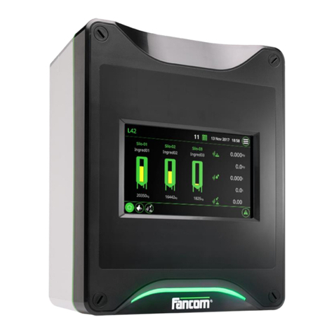
Fancom FB.1 User manual

G N D
F P
GNDFP

N.B.: The original, authentic version of this manual is the English version produced by Fancom B.V. or one of its
daughter companies (referred to further as Fancom). Any modifications introduced to this manual by third parties
have neither beenchecked nor approved by Fancom. Modifications are taken by Fancom toinclude translations into
languages other than English and the insertion and/or deletion of text and/or illustrations to/from the original
contents. Fancom cannot be held liable for any damages, injury, guarantee claims and other claims relating to this
type of modification, in as far as these modifications result in a content that differs from the original English version
of this manual produced by Fancom. For the latest information about product installation and operation, please
contact the customer service dept. and/or the technical service dept. of the Fancom companyconcerned. In spite of
the care taken when compiling this manual, if you should discover any errors, please inform Fancom B.V. in writing.
Fancom B.V., PO Box 7131, 5980 AC Panningen (the Netherlands).
Copyright © 2014 Fancom B.V.
Panningen (the Netherlands)
All rights reserved. Nothing from this manual may be copied, distributed or translated into other languages, partly or
wholly, without express prior written permission from Fancom. Fancom reserves the right to modify this manual
without notice. Fancom can give no guarantee, neither implicit nor explicit, for this manual. All risks are for the user.
This manual has been compiled with the utmost care. If, however, you should discover an error, please inform
Fancom B.V.
Art.Nr. 35911118
GB140401
Gndfp

Gndfp
i
g
1. General introduction .................................................................................................................................. 1
1.1 Fancom helpdesk ...........................................................................................................................1
1.2 How to use this manual ..................................................................................................................1
1.3 Safety instructions and warnings....................................................................................................1
2. Installing the FB.......................................................................................................................................... 2
2.1 Mounting the FB .............................................................................................................................2
2.2 Connecting the FB..........................................................................................................................2
2.3 Testing the FB................................................................................................................................5
3. Using the FB................................................................................................................................................ 6
3.1 Setting the switch ...........................................................................................................................6
3.2 The Reset button............................................................................................................................6
3.3 LED indicators................................................................................................................................ 7
4. Technical specifications ............................................................................................................................ 8
5. Appendix: Connection diagram................................................................................................................. 9
6. Appendix: EG declaration of conformity................................................................................................ 11

Gndfp
1
g
This manual has been compiled with the utmost care. If, however, you should discover an error, please inform
Fancom B.V.
For any questions and support, please contact the local Fancom Sales & Service Center.
The following symbols are used in this manual:
Tips and suggestions.
Note providing recommendations and additional information.
Warning indicating damage to the product if you do not follow procedures carefully.
Warning indicating danger to humans or animals.
Electrical shock hazard. Danger to humans and animals.
Example of a practical application of the described functionality.
Calculation example.
Before installing and commissioning the FB, read the safety instructions, provisions and conditions carefully. This
paragraph contains a number of general safety instructions. In the following paragraph, a number of specific safety
instructions are included in the installation instruction. The installation of the device and remedying of any
malfunctions should be performed by acertified electricalinstaller according to the applicable norms. The guarantee
does not apply if this product is installed in any other way than is indicated by Fancom and if the product's motor has
been opened and changes have been made to the product.
Never install a damaged FB! Notify your supplier of any damages.
Parts of this product may have sharp edges. Wearing safety gloves is therefore recommended.
Prevent electrostatic discharge (ESD) when working on the FB. Ensure that the workplace is clean and
dry.

Gndfp
2
g
Install the FB and associated components as follows:
1. Mount the FB (see page 2)
2. Connect the FB (see page 2)
3. Test the FB (see page 5)
Never place the FB in a place where the weather has direct influence (not in the sun, not in places
where the temperature can rise sharply etc.).
Place FB in a location such that the manual operation is easily reached (preferably outside a
department, due to corrosion from stall air).
Fancom recommends mounting the FB as follows:
1. Drill holes in the floor. You can use the drill template delivered with this.
2. Place the FB, glands on the bottom, on a flat floor surface.
3. Grout the glands with sealer to prevent penetration by moisture and dust and/or corrosive gasses.
Connect the FB as follows:
1. Set the power supply (see page 2).
2. Set the signalling memory (see page 2).
3. Set the audio or visual signal interval (see page 3).
4. Set the delay time (see page 3).
5. Set signalling contact inputs (see page 4).
6. Set external OFF indicator (see page 4).
7. Set phase control voltage (see page 4).
8. Set battery voltage (see page 5).
Determine the power supply setting with the J1 jumper setting:
Power supply voltage
J1
Single-phase power supply
Yes
Three-phase power supply
No
Determine the signalling memory with the J2, J3 and J10 jumper settings:
Signalling memory
J2
J3
J10 (a,b)
No signalling
No
No
Yes
Battery and phase signalling memory
Yes
No
Yes
Battery, phase and signalling input memory:
Yes
Yes
No

Gndfp
3
g
To save battery power during a power disruption, the audio or visual signal can be set in four ways. Determine the
time for the siren interval with the J4 and J5 jumper settings:
Audio or visual signal time interval
J4
J5
Continuous
No
No
1 minute on / 1 minute off
Yes
No
2 minutes on / 6 minutes off
No
Yes
1 minute on / 7 minutes off
Yes
Yes
You can set a delay time for the audio or visual signal and for the telephone dialler. Whenever a signalling situation
occurs, the audio or visual signal and/or telephone dialler will start working only after the passage of the delay time.
This allows you to prevent unnecessary signalling due to brief interruptions/deviations.
Telephone dialler delay time
Determine the delay time with the J6 and J7 jumper settings:
Telephone dialler delay time
J6
J7
None
No
No
2 minutes
Yes
No
4 minutes
No
Yes
6 minutes
Yes
Yes
Delay for the audio or visual signal
Determine the delay time with the potentiometer P4:
Delay for the audio or visual signal
P4
A minimum of 2 seconds (standard)
Turn completely to the left
Maximum + 60 seconds
Turn completely to the right

Gndfp
4
g
Determine whether the signalling is set by default to active or inactive using the J8 jumper setting:
If you set the J8 jumper setting to NC, then you must bridge all the signalling inputs not in use.
Signalling contact inputs
J8
Signalling contacts are broken when signalling starts
N.O.
Signalling contacts are made when signalling starts
N.C.
If the rotating switch is set to 0or T, then the signalling unit is turned off. Here, it's possible to connect an external
OFF indicator (e.g. a flashing light). When the rotating switch is set to 0or T, then this indicator gets turned on (the
flashing light comes on).
Determine the signalling contact input with the J8 jumper setting:
External OFF indicator
J9 (a,b)
Indication of OFF
Yes
Indication of not-OFF
No
The signalling unit has phase processing. If the phase voltage goes below 80 Vac, a signal is generated. If desired,
the phase control voltage can be adjusted for each phase with the potentiometers P1, P2 and P3.
Phase control voltage
P1
P2
P3
Phase 1
L1/R
Phase 2
L2/S
Phase 3
L3/T

Gndfp
5
g
Before setting the battery charge voltage, detach the battery clamp.
You can measure the battery charge across the soldering points "+" and "-" on the base of the CPB
(CN5 Ucharge Measure).
Determine the battery charge voltage with the potentiometer P5. The battery gets charged by default with 13.6 Vdc.
Battery voltage
P5
Lower battery charge
Turn to the left
Higher battery charge
Turn to the right
Fancom recommends manual testing of the audio or visual signal at least once per week.
You can test the signalling unit by setting the rotating switch to T. If the audio or visual signal activates after the
passage of any delay interval that may have been set, then the signalling unit is functioning correctly. Does the
audio or visual signal not activate? Then have your installer measure the battery voltage under load conditions. If
this is less than 10Vdc, then the battery is defective. If this is more than 10Vdc, then the audio or visual signal is
defective or not turned on properly.
The signalling unit performs an automatic battery check each day. This lasts for about 10 minutes. If the battery
voltage is OK, nothing happens. If the battery voltage is lower than 9Vdc, then the signalling output will activate and
the indicator light ( ) will light up (see page 6). You can save the signalling information in the signalling unit(see
page 2).

Gndfp
6
g
The switch on the front of the FB is used to set the signalling unit to:
Automatic (A),
off (0) or
test (T)
The FB is equipped with a reset button (reset). When this button is pressed, the audio or visual signal (e.g. siren)
and telephone dialler + will be inactive for 15 minutes. If the signalling situation is still present after this period of
time, then the audio or visual signal (e.g. siren) and telephone dialler will become active again.
If you have suspended a signal, you must always check the signalling unit to see whether any signals are
still present.

Gndfp
7
g
The FB is equipped with eight LED indicator lights.
Symbol
LED colour
Way of lighting up
Meaning
Red
Flashes
Signalling unit has been turned off or is in test
mode
Green
Continuously on
Signalling unit is in operation
Continuously off
Signalling unit has no power supply or is not in
operation
Flashes
Signalling unit is in battery-test mode
Red
Continuously on
Signalling situation
Red
Continuously on
Battery is malfunctioning
Red
Continuously on
One or more phases have been interrupted
(phase signalling)
Red
Continuously on
The audio or visual signal and the telephone
dialler output are temporarily inactive (+/- 15
min.). (After pressing the reset button)
Yellow
Continuously on
Telephone dialler output is inactive
Yellow
Continuously on
The audio or visual signal is inactive
If none of the LEDs is on continuously or flashing, then the signalling unit is not in operation. In this case,
check to see whether the signalling unit is connected correctly and whether the power supply/ battery are
OK.

Gndfp
8
g
Mains power
Mains voltage
1~ 230Vac (-10% - +6%)
3~ + N 230-400Vac (-10% - +6%)
Mains power frequency
50/60Hz
Max. Current
1~ 25mA
Electronic fuses (dim. 5x20mm)
Type slow, 50mA
Phase monitoring fuse 4x (dim. 5x20mm)
Type slow, 4A
Input
FB.1
D-E circuit (NC contact)
1-2 circuit (NO contact)
FB.8 /.16
8/16 signalling contacts (normally-open (NO) or normally-closed (NC) contacts)
Output
Audio or visual signal
12Vdc via battery (max. 1A.)
Relay contact
1× NO-P-NC, for telephone dialler, for example, 30Vac/60Vdc, max. 2A
1× NO, activates switch in 0 position, 30Vac/60Vdc, max. 2A
Manual operation FB.1/.8/.16
3-position selector switch
0-A-T
Reset
Pushbutton for turning the audio or visual signal off
FB.8/.16
8/16 switches (on-off) for turning on/off
signalling input
Battery
Power supply for the audio or visual signal
12Vdc - 1.2Ah
Housing
Plastic housing type with screw closure
IP54
Dimensions (LxWxH)
300×240×140mm
Weight (unpackaged)
FB.1
2.75 kg
FB.8
2.9 kg
FB.16
3.0 kg
Operating environment
Operating temperature range
0°C to +40°C
Storage temperature range
-10°C to +50°C
Relative humidity
< 95%, not condensing

Gndfp
9
g

Gndfp
10
g

Gndfp
11
g
Manufacturer:
Fancom B.V.
Address:
Industrieterrein 34
City:
Panningen (the Netherlands)
Hereby declares that the:
FB.1 / .8 / .16
Complies with the provisions of the:
1. Low voltage directive 2014/35/EU
according to NEN-EN-IEC 61010-1: 2010
2. EMC directive 2014/30/EU
Emission according to NEN-EN-IEC 61326-1: 2013
Immunity according to NEN-EN-IEC 61326-1: 2013
Place: Panningen
Date: 01-04-2014
Paul Smits
Managing Director

N.B.: De originele, authentieke versie van deze handleiding is de door Fancom B.V. of door een van haar
dochterondernemingen (verder aangeduid als Fancom) geproduceerde Engelstalige versie. Achteraf door derden
aangebrachte wijzigingen in deze handleiding zijn door Fancom noch gecontroleerd, noch goedgekeurd. Onder
wijzigingen verstaat Fancom o.a. het vertalen in een andere taal dan het Engels en het toevoegen en/of verwijderen
van tekst en/of illustraties aan/uit de originele inhoud. U kunt Fancom niet aansprakelijk stellen voor schade, letsel,
garantieclaims en andere claims die verband houden met dit soort wijzigingen, voor zover deze wijzigingen
resulteren in een inhoud die afwijkt van de authentieke door Fancom geproduceerde Engelstalige versie van deze
handleiding. Voor actuele informatie over productinstallatie en bediening, neem contact op met de klantenservice
en/of technische serviceafdeling van de betreffende Fancom-onderneming. Mocht u onverhoopt toch een fout
ontdekken, dan vragen wij u vriendelijk Fancom B.V. hiervan schriftelijk in kennis te stellen. Fancom B.V., Postbus
7131, 5980 AC Panningen (the Netherlands)
Copyright © 2014 Fancom B.V.
Panningen (the Netherlands)
Alle rechten zijn voorbehouden. Niets uit deze handleiding mag worden gekopieerd, gedistribueerd of vertaald in
andere talen, geheel of gedeeltelijk, zonder voorafgaande schriftelijke toestemming van Fancom. Fancom houdt
zich het recht voor om wijzigingen in de handleiding aan te brengen. Fancom kan echter geen garantie geven,
impliciet noch expliciet, voor deze handleiding. Het risico hiervan ligt volledig bij de gebruiker.
Deze handleiding is met de grootst mogelijke zorg samengesteld. Mocht u onverhoopt toch een fout ontdekken, dan
vragen wij u vriendelijk Fancom B.V. hiervan in kennis te stellen.
Art.nr. 35911118
NL140401
gNdfp

gNdfp
i
n
1. Algemene inleiding..................................................................................................................................... 1
1.1 Fancom-helpdesk...........................................................................................................................1
1.2 Hoe gebruikt u deze handleiding....................................................................................................1
1.3 Veiligheidsinstructies en waarschuwingen...................................................................................... 1
2. De FB installeren ........................................................................................................................................ 2
2.1 De FB monteren............................................................................................................................. 2
2.2 De FB aansluiten............................................................................................................................2
2.3 De FB testen...................................................................................................................................5
3. De FB gebruiken......................................................................................................................................... 6
3.1 De schakelaar instellen................................................................................................................... 6
3.2 De resetknop..................................................................................................................................6
3.3 LED-indicaties ................................................................................................................................ 7
4. Technische gegevens ................................................................................................................................ 8
5. Bijlage: Aansluitschema ............................................................................................................................ 9
6. Bijlage: EG-verklaring van overeenstemming........................................................................................ 11

gNdfp
1
n
Deze handleiding is met de grootst mogelijke zorg samengesteld. Mocht u onverhoopt toch een fout ontdekken, dan
vragen wij u vriendelijk Fancom B.V. hiervan in kennis te stellen.
Voor ondersteuning en antwoord op eventuele vragen kunt u het lokale Fancom Sales & Service Centre
raadplegen.
In deze handleiding worden de volgende symbolen gebruikt:
Tips en suggesties.
Opmerking met aanbevelingen en aanvullende informatie.
Waarschuwing duidend op schade aan het product als u procedures niet zorgvuldig uitvoert.
Waarschuwing duidend op gevaar voor mens of dier.
Kans op gevaarlijke elektrische schokken. Gevaar voor mens of dier.
Voorbeeld van een concrete toepassing van de beschreven functionaliteit.
Voorbeeld van een berekening.
Lees de veiligheidsinstructies, bepalingen en voorwaarden aandachtig voordat u de FB installeert en in gebruik
neemt. In deze paragraaf staan een aantal algemene veiligheidsinstructies. In de volgende paragraaf staan bij de
installatie-instructies ook een aantal specifieke veiligheidsinstructies. De installatie van het apparaat en het
verhelpen van eventuele storingen dient door een erkend installateur te worden uitgevoerd volgens de geldende
normen. De garantie is niet van toepassing als dit product op een andere wijze is geïnstalleerd dan door Fancom is
aangegeven en/of als de motor van het product is geopend en wijzigingen aan het product zijn aangebracht.
Installeer nooit een beschadigde FB! Meld eventuele beschadigingen aan uw leverancier.
Delen van dit product kunnen scherpe randen hebben. Het is daarom aan te bevelen om
veiligheidshandschoenen te dragen.
Voorkom elektrostatische ontlading (ESD) als u aan de FB werkt. Zorg voor een schone en droge
werkplek.

gNdfp
2
n
Installeer de FB en de bijbehorende onderdelen als volgt:
1. Monteer de FB (zie pagina 2).
2. Sluit de FB aan (zie pagina 2).
3. Test de FB (zie pagina 5).
Plaats de FB altijd buiten directe weersinvloeden (dus niet in de zon, niet op plekken waar detemperatuur
sterk kan oplopen etc.).
Plaats FB op een plaats waar de handbediening gemakkelijk bereikbaar is. (liefst buiten een afdeling,
vanwege de aantasting door de stallucht)
Fancom adviseert om de FB als volgt te monteren:
1. Boor gaten in de ondergrond. U kunt hiervoor de bijgeleverde boormal gebruiken.
2. Plaats de FB met de wartels aan de onderzijde op een vlakke ondergrond.
3. Kit de wartels af om het binnendringen van vocht, stof en/of agressieve gassen te voorkomen.
Sluit de FB als volgt aan:
1. Stel de voeding in (zie pagina 2).
2. Stel het signaleringsgeheugen in (zie pagina 2).
3. Stel het interval voor het audio- of visuele signaal in (zie pagina 3).
4. Stel de vertragingstijd in (zie pagina 3).
5. Stel de signaleringscontactingangen in (zie pagina 4).
6. Stel de externe UIT-indicatie in (zie pagina 4).
7. Stel de fasebewakingsspanning in (zie pagina 4).
8. Stel de accuspanning in (zie pagina 5).
Bepaal de voedingsspanning met de jumperinstelling J1:
Voedingsspanning
J1
Eenfasevoeding
Ja
Driefasenvoeding
Nee
Bepaal de instellingen voor het signaleringsgeheugen met jumpers J2, J3 en J10:
Signaleringsgeheugen
J2
J3
J10 (a,b)
Geen signalering
Nee
Nee
Ja
Accu- en fasesignaleringsgeheugen
Ja
Nee
Ja
Accu-, fase- en signaleringsingangsgeheugen:
Ja
Ja
Nee

gNdfp
3
n
Om bij stroomuitval energie uit de accu te besparen, kan het interval voor audio- of visuele signalen op vier
manieren worden ingesteld. Bepaal met jumperinstellingen J4 en J5 de tijd voor het sirene-interval:
Intervaltijd audio- of visueel signaal
J4
J5
Continu
Nee
Nee
1 minuut aan / 1 minuut uit
Ja
Nee
2 minuten aan / 6 minuten uit
Nee
Ja
1 minuut aan / 7 minuten uit
Ja
Ja
U kunt een vertragingstijd instellen voor het audio- of visuele signaal en voor de telefoonkiezer. Wanneer er een
signaleringssituatie optreedt, zal het audio- of visuele signaal en/of de telefoonkiezer pas na de vertragingstijd in
werking treden. Hiermee voorkomt u onnodige signalering als gevolg van kortstondige afwijkingen.
Vertragingstijd telefoonkiezer
Bepaal met jumperinstellingen J6 en J7 de vertragingstijd:
Vertragingstijd telefoonkiezer
J6
J7
Geen
Nee
Nee
2 minuten
Ja
Nee
4 minuten
Nee
Ja
6 minuten
Ja
Ja
Vertragingstijd audio- of visueel signaal
Bepaal de vertragingstijd met potentiometer P4:
Vertragingstijd audio- of visueel signaal
P4
Minimaal 2 seconden (standaard)
Geheel linksom draaien
Maximaal +60 seconden
Geheel rechtsom draaien

gNdfp
4
n
Bepaal met jumperinstelling J8 of de signaleringen standaard actief of inactief zijn:
Als u de jumperinstelling J8 op NC instelt, moet u alle niet-gebruikte signaleringsingangen
doorverbinden.
Signaleringscontactingangen
J8
Signaleringscontacten worden verbroken bij signaleringen
N.O.
Signaleringscontacten worden gemaakt bij signaleringen
N.C.
Als de draaischakelaar op 0of Tstaat, is de signaleringsunit uitgeschakeld. Hierbij is het mogelijk om een externe
UIT-indicatie aan te sluiten (bijvoorbeeld een zwaailamp). Wanneer de draaischakelaar op 0of Tstaat, wordt deze
indicatie ingeschakeld (de zwaailamp gaat branden).
Bepaal met jumperinstelling J8 de signaleringscontactingang:
Externe UIT-indicatie
J9 (a,b)
Indicatie bij UIT
Ja
Indicatie bij NIET UIT
Nee
De signaleringsunit ondersteunt fasebewaking. Wanneer de fasespanning onder 80 Vac daalt, volgt een
signalering. Indien gewenst kunt u met potentiometers P1, P2 en P3 de fasebewakingsspanning per fase
aanpassen.
Fasebewakingsspanning
P1
P2
P3
Fase 1
L1/R
Fase 2
L2/S
Fase 3
L3/T
Other manuals for FB.1
1
This manual suits for next models
2
Table of contents
Languages:
Other Fancom Control System manuals

Fancom
Fancom VLR.6 User manual

Fancom
Fancom WEBLINKBOX VERSION A2 User manual

Fancom
Fancom Lumina 35 User manual

Fancom
Fancom IMS User manual

Fancom
Fancom LUMINA 71 User manual

Fancom
Fancom 743 User manual

Fancom
Fancom LUMINA 38 User manual

Fancom
Fancom 743 User guide

Fancom
Fancom MRK.2 User manual

Fancom
Fancom INTELLITEK User manual
Popular Control System manuals by other brands

Woodward
Woodward ProAct I product manual

PE
PE Wideband O2 quick start guide

Felder
Felder Hammer HNC 47.82 Translation of the original operating instructions

Quick
Quick THRUSTERS COMMAND Manual for use and installation

OmniSense
OmniSense Sentry MK4 user guide

Racal Instruments
Racal Instruments 1260 VXI manual