Cardin Elettronica Mini FTR893 Series User manual

FTR893 C3
26-04-2011
ZVL315.02
CARDIN ELETTRONICA spa
Via del lavoro, 73 – Z.I. Cimavilla - 31013 Codognè (TV) Italy
Tel:
+39/0438.404011-401818
Fax:
+39/0438.401831
email (Italy):
email (Europe):
Http:
www.cardin.it
BARRIERA ALL'INFRAROSSO MODULATO "MINI FTR893C3"
Il presente manuale si rivolge a persone abilitate all'installazione di "APPARECCHI UTILIZZATORI DI
ENERGIAELETTRICA"erichiedeunabuonaconoscenzadellatecnica,esercitatainformaprofessionale.
Prima di dar inizio all’installazione prendere visione dei dispositivi di sicurezza previsti dal prodotto per
utilizzarli con la massima efcacia.
• Dispositivo classe 3 a doppio relé con scambi in serie, il contatto NC è conferme alle norme della
categoria 3 della UNI EN ISO 13849-1
(aggiornamento della EN954-1).
Attenzione! Solo per clienti dell’EU - Marcatura WEEE.
Il simbolo indica che il prodotto alla ne della propria vita utile deve essere raccolto
separatamente dagli altri riuti. L’utente dovrà pertanto conferire l’apparecchiatura agli
idonei centri di raccolta differenziata dei riuti elettronici ed elettrici, oppure riconsegnarla
al rivenditore al momento dell’acquisto di una nuova apparecchiatura di tipo equivalente,
in ragione di uno a uno. L’adeguata raccolta differenziata per l’avvio al riciclaggio, al
trattamento e allo smaltimento ambientalmente compatibile contribuisce ad evitare possibili effetti
negativi sull’ambiente e sulla salute e favorisce il riciclo dei materiali. Lo smaltimento abusivo del
prodotto da parte del detentore comporta l’applicazione delle sanzioni amministrative previste dalla
normativa vigente nello Stato Comunitario di appartenenza.
La barriera all'infrarosso modulato "FTR893C3" è composta da:
1) Una centralina di controllo FTR893C3
2) Un'ottica TX con cavo schermato NERO e supporto per ssaggio a pannello.
3) Un'ottica RX con cavo schermato GRIGIO e supporto per ssaggio a pannello.
Versione Lunghezza cavo TX (Nero) Lunghezza cavo RX (grigio)
FTR893C3 4 m 4 m
Possibilità di impiego
La barriera a raggio infrarosso modulato "
FTR893C3
" rappresenta un efciente sistema di sicurezza
per la protezione di passaggi o spazi soggetti ad installazioni automatizzate di ascensori. Il sistema è
adatto per applicazione su passaggi di luce compresa fra 0,5 e 2,5 metri all'interno di edici.
L'uso e l'installazione di questa apparecchiatura deve rispettare rigorosamente le indicazioni fornite
dal costruttore e le normative di sicurezza vigenti.
INSTALLAZIONE (fig.1-4)
Attenzione! Se si installano più FTR893C3 è opportuno, al ne di un corretto funzionamento,
che i coni di emissione delle singole ottiche non si sovrappongano. I due raggi devono essere
distanti circa 1,5 metri uno dall'altro.
1) Le ottiche vengono fornite complete di cavi che non è possibile allungare. Se invece si desidera
accorciarli è preferibile intervenire sul cavo RX cosicchè l'ottica RX risulti più vicina alla logica di
controllo ricevendo così un segnale più pulito.
N.B.: evitare di spellare il cavo schermato per più di 2 cm nella connessione alla morsettiera di
controllo (questo accorgimento diminuisce la sensibilità ai disturbi esterni).
2) Vericare attentamente che le superci sulle quali si devono ssare i supporti in plastica (fig. 3a)
siano in bolla e perfettamente affacciate fra loro in quanto non è consentita una regolazione esterna.
3) Determinare il punto in cui andrà collocata la logica di controllo tenendo conto della lunghezza
delle ottiche a disposizione; se l'installazione avviene all'esterno dell'edicio la logica di controllo
deve essere inserita in contenitore stagno (IP55).
4) Prevedere il passaggio dei cavi di collegamento dalla logica di controllo al punto di ssaggio delle
ottiche (fig. 3b) evitando il collocamento in canalette in cui vi siano cavi ad alta tensione.
5) Calcolare le altezze ("H" fig. 2) rispetto al suolo e marcare i punti di ssaggio dei supporti in plastica.
6) Utilizzando un trapano con punta da Ø12 effettuare i fori sui punti marcati (fig. 3).
7) Inserire i supporti in plastica (fig. 3a)
8) Fissare le ottiche al supporto inlando il cavo ed esercitando una pressione (fig. 3b). Una volta
bloccate, le ottiche non possono essere estratte dall'esterno (garanzia contro la manomissione).
9) Qualora sia necessario sostituire l'ottica, scollegare il cavo di collegamento ed esercitare una
pressione dall'interno verso l'esterno per liberare l'ottica dal suo supporto in plastica.
10) Effettuare i collegamenti rispettando rigorosamente lo schema riportato in fig. 4. La sezione minima
del cavo di alimentazione deve essere di 0,2 mm
2
(AWG#24).
11) Selezionare la tipologia del contatto in uscita: NC/8.2 kΩ.
12) Selezionarelaportatacomeindicatonellatabellaapagina4ricordandocheidatirelativiallaportata
si riferiscono ad una installazione ottimale che rispetta tutti i punti del paragrafo "Installazione".
Anomalie di funzionamento
• Il led verde è spento;
- vericare il collegamento elettrico;
- vericare il valore e polarità della tensione di alimentazione (12/24 Vac/dc).
• Il led rosso rimane sempre acceso:
- vericare che le ottiche siano correttamente allineate;
- vericare che il raggio non sia ostacolato;
- vericare l'integrità delle ottiche;
- vericare l'integrità dei cavi.
MODULATED INFRARED BARRIER "MINI" FTR893C3
These instructions are aimed at professionally qualied "installers of electrical equipment" and must
respect the local standards and regulations in force. Before commencing with the installation of this
appliance familiarise yourself with the safety devices required by the system, only then will you be
able to use them to great effect.
This class 3 equipment has a double relay with serial exchange. The NC contact conforms to
category
3 of the directive
UNI EN ISO 13849-1
(update of the EN954-1).
Attention! Only for EU customers - WEEE marking.
This symbol indicates that once the products life-span has expired it must be disposed
of separately from other rubbish.
The user is therefore obliged to either take the product to a suitable differential collec-
tion site for electronic and electrical goods or to send it back to the manufacturer if the
intention is to replace it with a new equivalent version of the same product. Suitable
differential collection, environmental friendly treatment and disposal contributes to avoiding negative
effects on the ambient and consequently health as well as favouring the recycling of materials. Illicitly
disposing of this product by the owner is punishable by law and will be dealt with according to the laws
and standards of the individual member nation.
The modulated infrared barrier "FTR893C3" is composed of:
1) A FTR893C3 control box
2) One transmitter sensor with a "BLACK" shielded cable and wall mounting support.
3) One transmitter sensor with a "GREY" shielded cable and wall mounting support.
Version Cable length TX (Black) Cable length RX (Grey)
FTR893C3 4 m 4 m
Use
The modulated infrared barrier "FTR893C3" constitutes an efcient control and safety system for
the protection of automatic installations such as lifts and is suitable for controlling passageways
of
from 0,5 to 2,5 meters inside buildings.
The use and installation of these appliances must rigorously respect the indications supplied by the
manufacturer and the safety standards and regulations in force.
INSTALLATION (fig. 1-4)
Caution! If you install more than one FTR893C3, in order to guarantee the correct operation,
the emission cones of the individual sensors should not overlap.
The two beams must be separated by at least 1,5 meters.
1) The sensors come complete with cables and though it is not possible to extend them you
may shorten them (in this case it's preferable to shorten the receiver cable so as to allow it to
be nearer the control box).
Warning: Do not peel the cables back by more than 2cm when wiring up to the control box as
this will reduce the device's level of resistance to external interference.
2) Make sure that the surfaces to which the sensor supports (fig. 3a) are to be tted are not inclined
and that they are perfectly aligned as once installed the sensors cannot be adjusted externally.
3) Work outthepoint atwhichthecontrolboxis tobettedby takingintoaccountthe lengthofthecables.
If the control box is to be installed outdoors it must be protected by a waterproof container (IP55).
4) Run the cables from the control box to the sensors (fig. 3b) making sure that they are not passed
through ducts containing high tension wires.
5) Work out the height ("H" fig. 2) and mark the points at which the plastic supports are to be tted.
6) Drill a Ø12 hole at each installation point (fig. 3).
7) Insert the plastic supports (fig. 3a)
8) Fix the sensors to the supports by rst inserting the cable and then pressing down on the sensor
until it snaps into position (fig. 3b). Once they have been fastened down the sensors cannot be
extracted externally (these are anti-tampering devices).
9) If you have replace the sensor; rst disconnect the cable from the socket and then press from
the inside towards the outside to free the sensor from its plastic support.
10) Carry out the electrical connection exactly following the attached wiring diagram (fig. 4). The
minimum cable cross section area for the power cable is 0,2 mm2(AWG #24).
11) Select
the type of output contact: NC/8.2 kΩ
12) Select the range as indicated in the table on page 4 remembering that the range values are
strictly dependent on a well executed installation which respects all the points specied in the
paragraph "Installation".
Operational anomalies
• The green led is off
- Check the electrical connection
- Check the power supply rating and polarity (12/24 Vac/dc).
• The red led remains constantly lit
- Make sure that the sensors are correctly aligned
- make sure that the beam is not interrupted;
- check the integrity of the sensors;
- check the integrity of the cables.
ITALIANO ENGLISH
ZVL315.02: Mod.: 27-06-2011
This product has been tried and tested in the manufacturer's laboratory, du-
ring the installation of the product follow the supplied indications carefully.
MODEL DATE
SERIAL NUMBER SERIES

DEUTSCH
MODULIERTE INFRAROTLICHTSCHRANKE "MINI FTR893C3"
Hinweis:Das vorliegende Handbuch wendetsich an Personen, die zur Installation von "ELEKTROGERÄ-
TEN" befähigt sind und setzt eine gute beruiche Kenntnis der Technik voraus. Bevor mit der Installation
begonnen wird, sollte das vorliegende Heft aufmerksam gelesen werden. Insbesondere sollten die vom
Produkt vorgesehenen Sicherheitseinrichtungen zwecks bester Efzienz in Augenschein genommen
werden. Gerät der Klasse 3 mit doppeltem Relais mit Umschaltungen in Serie, der NC-Kontakt entspricht
den Vorschriften der Kategorie 3 der UNI EN ISO 13849-1 (Aktualisierung der EN954-1).
Achtung! Nur für EG-Kunden – WEEE-Kennzeichnung.
Das Symbol zeigt an, dass das Produkt am Ende seines Lebenszyklus getrennt von
anderen Abfällen gesammelt werden muss. Der Benutzer muss daher das Gerät in
geeignete Zentren für die getrennte Sammlung von Elektronik- und Elektroschrott brin-
gen oder zum Zeitpunkt des Erwerbs eines neuen Geräts gleicher Art im Verhältnis eins
zu eins beim Händler abgeben. Die geeignete getrennte Sammlung für die Zuführung
zum Recycling, zur Aufbereitung und zur umweltfreundlichen Entsorgung trägt dazu bei, mögliche
negative Auswirkungen auf die Umwelt und die Gesundheit zu vermeiden und fördert das Recycling
der Materialien. Die widerrechtliche Entsorgung des Produkts durch den Besitzer führt zur Anwendung
der von den geltenden Vorschriften im Mitgliedstaat der Europäischen Gemeinschaft vorgesehenen
Verwaltungsstrafen.
Die modulierte Infrarotlichtschranke "FTR893C3", besteht aus:
1) Der Kontrollzentrale FTR893C3;
2) Ein Sender Optik mit SCHWARZEM abgeschirmten Kabel und Träger zur Befestigung an
der Fläche.
3) Ein Empfänger Optik mit GRAUEM abgeschirmten Kabel und Träger zur Befestigung an der
Fläche.
Ausführung Sender Kabellänge (Schwarz)Empfänger Kabellänge(Grau)
FTR893C3 4 m 4 m
Einsatzmöglichkeiten
Die Infrarotlichtschranke "FTR893C3" stellt ein wirksames Sicherheitssystem zum Schutz
von Durchgängen oder Flächen bei denen automatische Installationen von Aufzügen dar.
Sie ist geeignet für Durchgänge mit einer Weite zwischen 0,5 und 2,5 m innerhalb von
Gebäuden. Die Verwendung und die Installation dieser Geräte muss unter der genauen
Befolgung der vom Hersteller gegebenen Anweisungen und der geltenden Sicherheitsbe-
stimmungen erfolgen.
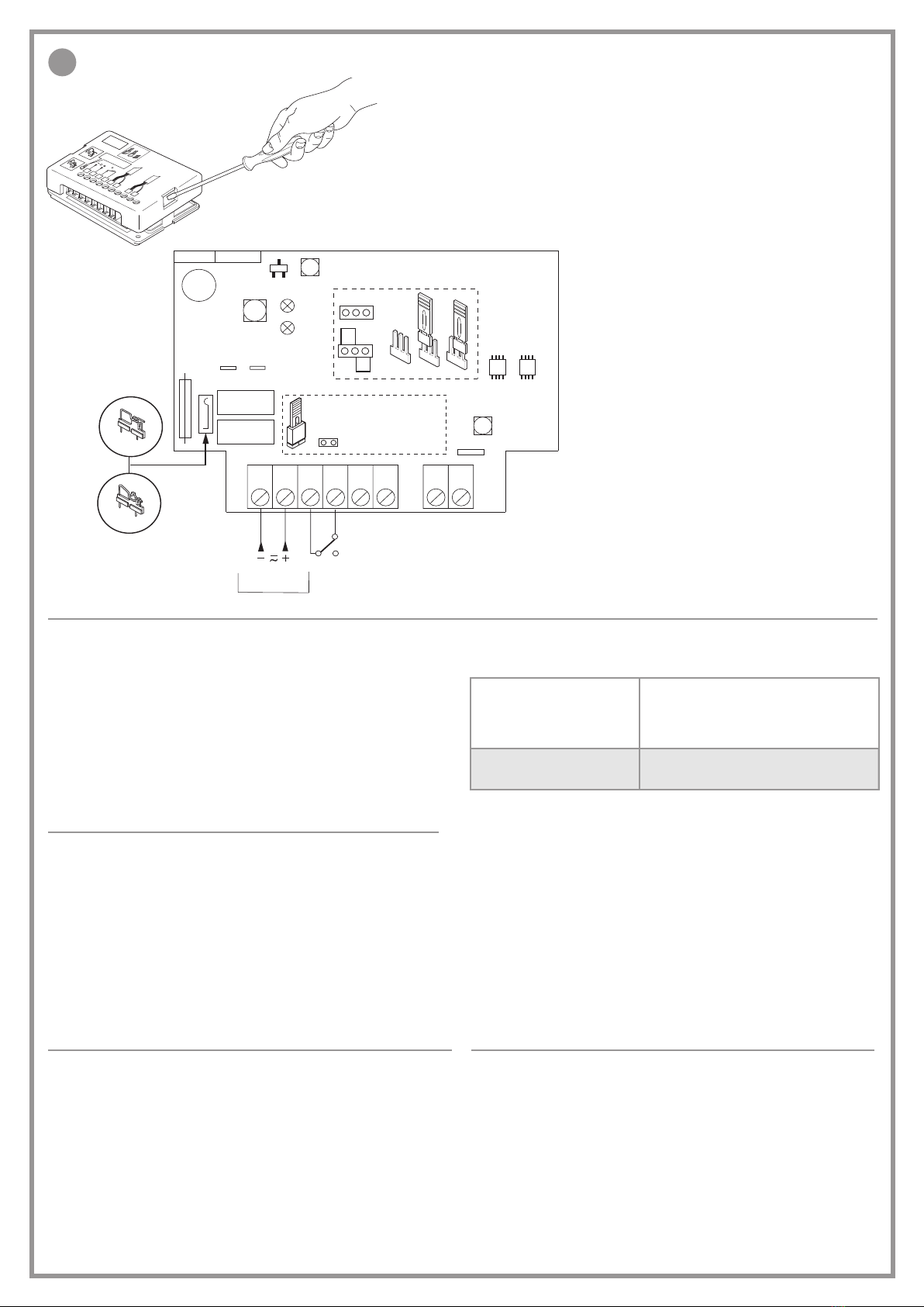
Installation (siehe Abb. 1 - 4)
Achtung!Wenn mehrere FTR893C3installiert werden,dürfen sich die Strahlungskegelder
einzelnen Optiken nicht überlagern, um eine korrekte Funktionsweise zu gewährleisten.
Die beiden Lichtstrahlen müssen einen Abstand voneinander von zirka 1,5 m schaltet
werden.
1) Die Optiken sind komplett mit ihren Kabeln geliefert; ein Verlängern der Kabel ist nicht mög-
lich; sie können aber verkürzt werden (in diesem Fall ist die Verkürzung des Empfängerkabels
vorzuziehen, so dass die Optik des Empfängers näher zur Kontrollogik kommt).
Achtung: Vermeiden Sie, das abgeschirmte Kabel auf mehr als 2 cm beim Anschluss an die
Klemmleiste der Kontrollogik abzuisolieren (dies verringert die Empfänglichkeit gegenüber
Störungen von außen).
2) Prüfen Sie aufmerksam, ob die Oberächen, auf denen die Plastikhalter befestigt werden sollen
(Abb. 3a), waagerecht sind und sich perfekt gegenüberliegen, da die Optiken nicht von außen
eingestellt werden können.
3) Bestimmen Sie die Stelle, an der die Kontrollogik untergebracht werden soll, wobei Sie sich die
Kabellänge der zu Verfügung stehenden Optiken vor Augen halten sollten. Wenn die Installation
außerhalb des Gebäudes erfolgt, muss die Kontrollogik in einem wetterdichten Gehäuse (IP55)
untergebracht werden.
4) Bereiten Sie den Verlauf der Verbindungskabel von der Kontrollogik bis zur Befestigungsstelle
derOptiken(Abb.3b) vor, wobei dasZusammenlegenmitStarkstromkabelnindenKabelkanälen
vermieden werden sollte.
5) Berechnen Sie die Höhen vom Boden ("H" Abb. 2) und markieren Sie die Befestigungspunkte
der Plastikhalter.
6) Mit einem Bohrer, der mit einer Bohrspitze Ø12 ausgestattet ist, bohren Sie die Löscher an
den markierten Punkten (Abb. 2).
7) Setzen Sie die Plastikhalter ein (Abb. 3a).
8) Befestigen Sie die Optiken am Träger, indem Sie das Kabel einführen und Druck ausüben (Abb.
3b). Nachdem die Optiken befestigt sind, können sie von außen nicht mehr herausgezogen
werden (Garantie gegen Mißgriffe).
9) Falls eine Ersetzung der Optik notwendig werden sollte, lösen Sie das Verbindungskabel und
üben Sie Druck von innen nach außen aus, um die Optik aus ihrer Plastikhalterung zu befreien.
10) Führen Sie die Anschlüsse aus, wobei Sie rigoros das in der (Abb.4) wiedergegebene Schema
befolgen. Der Durchmesser des Stromversorgungskabels sollte mindestens 0,2 mm2betragen
(AWG#24).
11) Die Art des Kontakts im Ausgang auswählen: NC/8.2 kΩ.
12) Wie in der Tabelle auf Seite 4 angegeben die Reichweite auswählen, wobei darauf zu achten
ist, dass sich die Daten für die Reichweite auf eine optimale Installation beziehen, die alle
Punkte des Abschnitts "Installation" erfüllt.
Betriebsstörungen
• Die grüne Led leuchtet nicht.
- Überprüfen Sie den elektrischen Anschluss.
- Den Wert und die Polarität der Versorgungsspannung
(12/24 Vac/dc)
überprüfen.
• Die rote Led leuchtet dauernd.
- Die Optiken sind nicht ausgerichtet
- Überprüfen Sie, ob der Lichtstrahl behindert wird;
- Überprüfen Sie die Unversehrtheit der Optiken;
- Überprüfen Sie die Unversehrtheit der Kabel.
FRANÇAIS DEUTSCH
BARRIERE A INFRAROUGE MODULE "MINI FTR893C3"
Remarque: Ce livret est destiné à des personnes titulaires d’un certicat d’aptitude professionnelle
pour l’installation des "APPAREILS ÉLECTRIQUES" et requiert une bonne connaissance de la tech-
nique appliquée professionnellement. Avant de procéder à l’installation, lire attentivement ce livret.
En particulier, se familiariser avec les dispositifs de sécurité prévus sur le produit an de pouvoir les
utiliser au mieux.
Appareil de classe 3 à double relais avec contact inverseur en série. Le contact N.F. est conforme aux
normes de la catégorie 3 de la UNI EN ISO 13849-1 (mise à jour de la EN954-1).
Attention! Seulement pour les clients de l'EU - Marquage WEEE. Ce symbole indique
l’obligation de ne pas éliminer l’appareil, à la n de sa durée de vie, avec les déchets
municipaux non triés et de procéder à sa collecte sélective. Par conséquent, l’utilisateur
doit remettre l’appareil à un centre de collecte sélective des déchets électroniques et
électriques ou au revendeur qui est tenu, lorsqu’il fournit un nouvel appareil, de faire en
sorte que les déchets puissent lui être remis, sur une base de un pour un, pour autant que
l’appareil soit de type équivalent à celui qu’il fournit. La collecte sélective des équipements électriques et
électroniques en vue de leur valorisation, leur traitement et leur élimination dans le respect de l’environnement
contribue à éviter la nocivité desdits équipements pour l’environnement et pour la santé et à encourager
leur recyclage. L’élimination abusive de l’équipement de la part du détenteur nal comporte l’application
des sanctions administratives prévues par les normes en vigueur dans l’État Membre d’appartenance.
La barrière à l’infrarouge modulé "FTR893C3" est constituée de:
1) la centrale de contrôle FTR893C3;
2) une tête optique TX munie de câble blindé NOIR et de support de xation sur panneau;
3) une tête optique RX munie de câble blindé GRIS et de support de xation sur panneau.
Version Longueur câble TX (Noir)Longueur câble RX (Gris)
FTR893C3 4 m 4 m
Applications possibles (voir fig.1 - 4)
La barrière à l’infrarouge modulé "FTR893C3" est un système de sécurité efcace, conçu pour
la protection de passages ou d’endroits destinés à des installations automatisées d’ascenseurs.
Le système est indiqué pour des passages d’une dimension comprise entre 0,5 et 2,5 m à
l'intérieur des bâtiments.
Pour l’utilisation et l’installation de cet appareil, se conformer aux indications fournies par le
Constructeur et aux normes de sécurité en vigueur.
Installation (voir fig.1 - 4)
Attention! En cas d’installation de plusieurs FTR893C3, il est nécessaire pour obtenir un
bon fonctionnement que les cônes d’émission des têtes optiques ne se chevauchent pas
et les deux faisceaux doivent être distants l’un de l’autre de 1,5 m environ.
1) Les têtes optiques sont fournies munies de câbles; il n’est pas possible de rallonger les
câbles. Ceux-ci peuvent par contre être raccourcis (dans ce cas il est conseillé de raccourcir
le câble RX de façon que la tête optique RX soit plus proche de la logique de contrôle).
Attention: éviter de dénuder le câble blindé de plus de 2 cm dans la connexion du bornier
de la logique de contrôle (ceci réduit la sensibilité aux parasites).
2) Vérier soigneusement que les surfaces qui reçoivent les supports en plastique (fig.3a)
soient à niveau et parfaitement alignées l’une par rapport l’autre, considéré que les têtes
optiques ne permettent pas un réglage de l’extérieur.
3) Déterminer l’emplacement de la logique de contrôle en tenant compte de la longueur des
têtes optiques à disposition.
En cas d’installation à l’extérieur de l’édice, la logique de contrôle doit être logée dans un
boîtier étanche (IP55).
4) Prévoir le passage des câbles de branchement de la logique de contrôle jusqu’au point
de xation des têtes optiques (fig. 3b). Éviter de les faire passer dans des conduites dans
lesquelles se trouvent des câbles haute tension.
5) Calculer les hauteurs ("H" fig. 2) par rapport au sol et tracer les points de xation des
supports en plastique.
6) Utiliser une perceuse et un forêt de Ø12 pour pratiquer les trous aux endroits tracés (fig. 3).
7) Fixer les supports en plastique (fig. 3a).
8) Enler le câble et xer les têtes optiques au support en exerçant une certaine pression (fig.
3b). Une fois xées, les têtes optiques ne peuvent pas être extraites de l’extérieur (sécurité
contre les risques de vandalisme).
9) En cas de remplacement d’une tête optique, débrancher le câble de branchement et exercer
une pression de l’intérieur vers l’extérieur pour la dégager de son support en plastique.
10) Effectuer le branchement en observant scrupuleusement le schéma reporté en (fig. 4). La
section minimale du câble d’alimentation doit être de 0,2 mm2(AWG#24).
11) Sélectionner le type de contact en sortie: NC/8.2 kΩ
12) Sélectionner la portée suivant les indications du tableau de la page 4 en sachant que les
données inhérentes à la portée sont valables pour une installation optimale qui satisfait
tous les points du paragraphe "Installation".
Anomalies de fonctionnement
• Le led vert est éteint:
- vérier le branchement électrique;
- contrôler la valeur et la polarité de la tension d’alimentation
(12/24 Vac/dc).
• Le led rouge reste toujours allumé.
- vérier que les têtes optiques sont bien alignées
- vérier que le faisceau ne soit pas interrompu;
- vérier l’intégralité des têtes optiques;
- vérier l’intégralité des câbles.

L=Max. 2,5 m
Rx Grey Cable 4 m
Tx Cable 15 m max.
Optic TX Optic RX
20
2
1
LD
737B
Tx Black Cable 4 m
60
90
FTR893C3-R
Description :
Product Code :
Date :
Drawing number :
P.J.Heath
CARDIN ELETTRONICA S.p.A - 31020 San Vendemiano (TV) Italy - via Raffaello, 36 Tel: 0438/401818 Fax: 0438/401831
Draft :
FTR893C3-R
DM0821
26-05-2001
Dimensioni d'ingombro ricevitore mini
All rights reserved. Unauthorised copying or use of the information contained in this document is punishable by law
CLOSED = NC
OPEN = 8,2KΩ
J2
NC/8,2KΩ
BARRERA AL INFRARROJO MODULADO "MINI FTR893C3"
Advertencias: Este manual se dirige a personas habilitadas para la instalación de "aparatos utilizadores
de energía eléctrica" y exige el buen conocimiento de la técnica, realizada profesionalmente. Antes de
dar inicio a la instalación, véase los dispositivos de seguridad dispuestos para el producto para podarlos
utilizar con la máxima ecacia.
Equipo de categoría 3 provisto de doble relé con intercambios en serie; el contacto NC es conforme a las
normas de la categoría 3 de la UNI EN ISO 13849-1 (actualización de la norma EN954-1).
¡Atención! Solo para clientes de la Unión Europea - Marcación WEEE.
El símbolo indica que el producto, una vez terminada su vida útil, debe ser recogido
por separado de los demás residuos. Por lo tanto, el usuario deberá entregar el
equipo en los centros de recogida selectiva especializados en residuos electrónicos
y eléctricos, o bien volverlo a entregar al revendedor al momento de comprar un
equipo nuevo equivalente, en razón de uno comprado y uno retirado.
Larecogidaselectivadestinadaalreciclado,altratamientoyalagestiónmedioambientalcompatible
contribuyeaevitarlosposiblesefectosnegativosenelmedioambiente y en la salud, yfavoreceel reci-
cladodelosmateriales.Lagestiónabusivadelproductoporpartedelposesorimplicalaaplicacióndelas
sancionesadministrativas previstaspor lanormativavigente enelEstadocomunitario alquepertenece.
La barrera al infrarrojo FTR893C3 comprende:
1) La central de control FTR893C3
2) Uno dispositivo óptico TX provisto de cable de conductores encerrados NEGRO y soporte
para la jación en el tablero.
3) Uno dispositivo óptico RX provisto de cable de conductores encerrados GRIS y soporte
para la jación en el tablero.
Versión Longitud cable TX (negro)Longitud cable RX (gris)
FTR893C3 4 m 4 m
Posibilidad de uso
La barrera de radiación infrarroja modulada "FTR893C3" representa un eciente sistema de
seguridad para la protección de pasos o espacios sometidos a instalaciones automatizadas
de ascensores.
El sistema es adecuado para la aplicación en pasos cuya luz es de 0,5 a 2,5 m al interior de los
edicios. El uso y la instalación de este aparato debe cumplir rigurosamente las indicaciones
facilitadas por el fabricante y las normas de seguridad vigentes.
Instalación véase fig. 1 - 4)
Cuidado! Si se instalan varios aparatos FTR893C3 es oportuno, a n de obtener su fun-
cionamiento correcto, que los conos de emisión de los dispositivos ópticos sencillos no
se superpongan. Los dos haces deben estar a 1,5 metro aproximadamente uno de otro.
1) Los dispositivos ópticos se suministran provistos de cables; los cables no se pueden
alargar, sin embargo es posible cortarlos (en tal caso es preferible cortar el cable RX así
que el dispositivo óptico RX está más cerca de la lógica de control).
Cuidado: No pelar más de 2 cm el cable de conductores encerrados para la conexión en la
bornera de la lógica de control (esto reduce la sensibilidad hacia las interferencias exteriores).
2) Comprobar con sumo esmero que las supercies donde se deben jar los soportes de
plástico (fig. 3a) están llanas y perfectamente enfrentadas entre sí ya que los dispositivos
ópticos no permiten la regulación exterior.
3) Determinar el punto preciso donde se va a colocar la lógica de control teniendo en cuenta
la longitud de los dispositivos ópticos disponibles; si la instalación se realiza al exterior del
edicio, la lógica de control debe colocarse en el contenedor estanco (IP55).
4) Disponer el paso de los cables de conexión desde la lógica de control hasta el punto de
jación de los dispositivos ópticos (fig. 3b) sin pasarlos por los conductos donde hay cables
de alta tensión.
5) Calcular las alturas ("H" fig. 2) respecto al suelo y marcar los puntos de jación de los
soportes de plástico.
6) Utilizando un taladro con una broca de Ø12, realizar los agujeros en los puntos que se
acaban de marcar (fig. 3).
7) Introducir los soportes de plástico (fig. 3a).
8) Fijar los dispositivos ópticos en el soporte introduciendo el cable y ejerciendo alguna presión
(fig. 3b). Una vez bloqueados, los dispositivos ópticos no se pueden sacar desde el exterior
(garantía contra las manipulaciones).
9) De ser necesario sustituir el dispositivo óptico, desconectar el cable de conexión y ejercer
alguna presión desde el interior hacia el exterior para liberar el dispositivo óptico de su
soporte de plástico.
10) Llevar a cabo las conexiones observando rigurosamente el esquema representado en
la (fig. 4).La sección mínima del cable de alimentación debe ser de 0,2 mm2(AWG#24).
11) Seleccionar el tipo de contacto en salida: NC/8.2 kΩ
12) Seleccionar el alcance como se indica en la tabla de página 4, recordando que los datos
del alcance se reeren a una instalación ideal que respeta todos los puntos del apartado
“Instalación”.
Funcionamiento incorrecto
• El piloto verde está apagado:
- comprobar las conexiones eléctricas;
- comprobar el valor y la polaridad de la tensión de alimentación
(12/24 Vac/dc)
.
• El piloto rojo queda siempre encendido:
- los dispositivos ópticos no están alineados;
- comprobar que el haz no está obstaculizado;
- comprobar la integridad de los dispositivos ópticos;
- comprobar la integridad de los cables.
ESPAÑOL
FTR893
H
TX RX
TX RX
Esempio d'installazione fotocellule mini
FTR893 (inst)
26-05-2011
DI0563 Description :
Product Code :
Date :
Drawing number :
P.J.Heath
CARDIN ELETTRONICA S.p.A - 31020 San Vendemiano (TV) Italy - via Raffaello, 36 Tel: 0438/401818 Fax: 0438/401831
Draft :
All rights reserved. Unauthorised copying or use of the information contained in this document is punishable by law
12mm
A
B
Installazione fotocellule mini
CDR891
16-04-96
DI0032 Description :
Product Code :
Date :
Drawing number :
P.J.Heath
CARDIN ELETTRONICA S.p.A - 31020 San Vendemiano (TV) Italy - via Raffaello, 36 Tel: 0438/401818 Fax: 0438/401831
Draft :
All rights reserved. Unauthorised copying or use of the information contained in this document is punishable by law
CDR891
Misure d'ingombro - Overall dimensions - Mesures d'encombrement -
Außenabmessungen - Dimensiones del espacio ocupado
1
Esempi di installazione - Installation examples - Exemples d'installation -
Installationsbeispiele - Ejemplos de instalación
2
Installazione fotocellule - Fitting the photocell - Installation des cellules
photoélectriques - Installation der Lichtschranke - Instalación fotocélulas
3
LA DISTANZA TX - RX NON
DEVE SUPERARE 2,5 METRI.
LA DISTANZA "H" DIPENDE
DALLA GRANDEZZA DELLA
PERSONA O OGGETTO CHE
DEVE ESSERE RILEVATO.
THE DISTANCE TX - RX MUST
NOT EXCEED 2,5 METRES
THE DISTANCE "H" DEPENDS
ON THE MINIMUM HEIGHT
OF THE OBJECT OR PERSON
WHICH IS TO BE DETECTED.
LA DISTANCE TX-RX NE DOIT
PAS DÉPASSER LES 2,5 MÈTRES.
LA DISTANCE "H" DÉPEND DE LA HAUTEUR DE LA PERSONNE OU DU MATÉRIEL QUI DOIT
ÊTRE DÉTECTÉ.
DER ABSTAND TX - RX DARF
NICHT MEHR ALS 2,5 METER
BETRAGEN.
DER ABSTAND "H" HÄNGT
VON DER GRÖSSE DER ZU
ERFASSENDEN PERSON
ODER OBJEKTES AB.
LA DISTANCIA TX-RX NO DEBE
SUPERAR 2,5 METROS.LA
DISTANCIA "H" DEPENDE DE
LA ALTURA DE LA PERSONA
U OBJETO QUE DEBEN SER
DETECTADOS.

2
13456789
Aperture ricevitore MINI
CDR892C3
23-03-2011
DM0819 Description :
Product Code :
Date :
Drawing number :
P. J.Heath
CARDIN ELETTRONICA S.p.A - 31020 San Vendemiano (TV) Italy - via Raffaello, 36 Tel: 0438/401818 Fax: 0438/401831
Draft :
All rights reserved. Unauthorised copying or use of the information contained in this document is punishable by law
CDR892C3
1 3 4 5 6
27
BLACK
GREY
8
RX1 RX2
CLOSED = NC
OPEN = 8,2KΩ
J2
J1
12V
Pos.A
Pos.B
24V
P2 P1P0
J3
CS1398 DC0523
123456 7 8
Alimentazione
Power supply
RX
TX
NC /
8.2 kΩ
BRAID
BRAID
L1
L2
J3
P2
P1
P1 P2
J2
CLOSED = NC
OPEN = 8,2KΩ
P0
P0
RELAY
RELAY
OPEN
CLOSED
J1
24V
12V
Pos.A
Pos.B
Fotocellule scheda mini un raggio
FTR893C3-R
26-05-2011
DC0522 Description :
Product Code :
Date :
Drawing number :
P.J.Heath
CARDIN ELETTRONICA S.p.A - 31020 San Vendemiano (TV) Italy - via Raffaello, 36 Tel: 0438/401818 Fax: 0438/401831
Draft :
All rights reserved. Unauthorised copying or use of the information contained in this document is punishable by law
FTR893C3-R
Legenda
J1 Jumper commutazione 12-24 V
J2 Jumper di selezione
NC/8.2 kΩ
J3 Jumper di selezione portata
L1 Led verde di alimentazione
L2 Led rosso di allarme
Legend
J1 Jumper 12-24 V selection
J2 Selection Jumper
NC/8.2 kΩ
J3 Range selection jumpers
L1 Green power on led
L2 Red alarm led
Légende
J1 Jumper commutation 12-24 V
J2 Jumper sélection
NF/8.2 kΩ
J3 Jumper sélection portée
L1 Led vert mise sous tension
L2 Led rouge alarme
Zeichenerklärung
J1 Jumper Umschaltung 12-24 V
J2 Jumper auswahl
NC/8.2 kΩ
J3 Jumper auswahl der Reichweite
L1 Grüne Led für Stromversorgung
L2 Rote Led für Alarm
Leyenda
J1 Jumper conmutación 12-24 V
J2 Jumper selección
NC/8.2 kΩ
J3 Jumper selección alcance
L1 Piloto verde de alimentación
L2 Piloto rojo de alarma
Connessioni - Connections - Connexions - Anschlüsse - Conexiones
4
Caratteristiche tecniche
- Alimentazione:............................................................................................ 12/24 Vac/dc
- Assorbimento max: ............................................................................................... 55 mA
- Temperatura di funzionamento: ................................................................. -10...+55 °C
- Lunghezza d'onda dell'emissione I.R................................................................. 950 nm
- Frequenza portante.............................................................................................. 31 kHz
- Frequenza modulante .......................................................................................... 200 Hz
- Apertura del cono di emissione. ................................................................................±7°
- Grado di protezione (ottiche) ................................................................................... IP55
- Tempo di intervento relé.........................................................................................25 ms
- Ritardo alla diseccitazione ...................................................................................100 ms
- Massima potenza commutabile dal relé con carico resistivo ac/dc: ........ 60 VA / 28 W
- Tensione max di contatto................................................................................ 30 Vac/dc
- Corrente max. ..................................................................................................... 500 mA
Technical specifications
- Power supply voltage:............................................................................... 12/24 Vac/dc
- Max. power consumption: ....................................................................................55 mA
- Operating temperature range: .................................................................... -10...+55 °C
- Emission wavelength I.R.....................................................................................950 nm
- Carrier frequency..................................................................................................31 kHz
- Modulation frequency ..........................................................................................200 Hz
- Emission cone opening............................................................................................. ±7°
- Protection grade (optical sensors) ...........................................................................IP55
- Relay intervention time.......................................................................................... 25 ms
- Drop out delay.....................................................................................................100 ms
- Max commutable power at the relay load ac/dc:......................................60 VA / 28 W
- Max voltage at contacts..................................................................................30 Vac/dc
- Max current .........................................................................................................500 mA
Caractéristiques techniques
- Alimentation:................................................................................................ 12/24 Vac/dc
- Intensité maxi. absorbée:...................................................................................... 55 mA
- Température de fonctionnement: ................................................................-10...+55 °C
- Longueur d’onde de l’émission I.R......................................................................950 nm
- Fréquence porteuse ............................................................................................. 31 kHz
- Fréquence de la modulation ................................................................................ 200 Hz
- Ouverture du cône d’émission................................................................................... ±7°
- Indice de protection (têtes optiques) ....................................................................... IP55
- Temps d’intervention du relais...............................................................................25 ms
- Retard à la désexcitation .....................................................................................100 ms
- Puissance maximum commutable par le relais charge en ac/dc: ............. 60 VA / 28 W
- Tension maxi. du contact................................................................................ 30 Vac/dc
- Max courant ........................................................................................................500 mA
Technische Daten
- Stromversorgung:........................................................................................ 12/24 Vac/dc
- max. Stromaufnahme.:.......................................................................................... 55 mA
- Betriebstemperatur: ....................................................................................-10...+55 °C
- Wellenlänge des I.R.-Lichtstrahls.........................................................................950 nm
- Trägerfrequenz...................................................................................................... 31 kHz
- Modulationfrequenz ............................................................................................. 200 Hz
- Öffnung des Strahlungskegels:.................................................................................. ±7°
- Schutzgrad (Optiken): .............................................................................................. IP55
- Relaisansprechzeit: ................................................................................................25 ms
- Abfallverzögerung: ...............................................................................................100 ms
- vom Relais, umschaltbare Höchstleistung Belastung:............................... 60 VA / 28 W
- max. Kontaktspannung................................................................................... 30 Vac/dc
- max. Strom.......................................................................................................... 500 mA
Características técnicas
- Alimentación:............................................................................................... 12/24 Vac/dc
- Absorción máx.: .................................................................................................... 55 mA
- Temperatura de funcionamiento: ................................................................-10...+55 °C
- Longitud de onda de la radiación infrarroja:........................................................950 nm
- Frecuencia portadora........................................................................................... 31 kHz
- Modulación de frecuencia.................................................................................... 200 Hz
- Apertura del haz de emisión infrarroja:...................................................................... ±7°
- Grado de protección (dispositivos ópticos):........................................................... IP 55
- Tiempo de intervención relé:..................................................................................25 ms
- Retardo en la desexcitación: ...............................................................................100 ms
- potencia máxima conmutable con carga resistiva
en ac/dc:..................... 60 VA / 28 W
- Tensión máx. de contacto............................................................................... 30 Vac/dc
- Máx corriente ...................................................................................................... 500 mA
SELEZIONE PORTATA - RANGE SELECTION - SÉLECTION PORTÉE
AUSWAHL DER REICHWEITE - SELECCIÓN ALCANCE
Posizione jumper J3 Portata interno max.
Position of jumper J3 Internal range max.
Position sélecteur J3 Portée intérieure maxi.
Wahlschalter stellung J3 Interne Reichweite max.
Posición selector J3 Alcance interior máx.
P0 0,8 m
P2 1,5 m
P1 2,5 m
This manual suits for next models
1
Other Cardin Elettronica Security Sensor manuals

Cardin Elettronica
Cardin Elettronica CDR Series User manual

Cardin Elettronica
Cardin Elettronica Mini CDR Series User manual

Cardin Elettronica
Cardin Elettronica METALDEC Series User manual

Cardin Elettronica
Cardin Elettronica CDR Series User manual

Cardin Elettronica
Cardin Elettronica CDR 871 User manual

Cardin Elettronica
Cardin Elettronica MINI CDR Series User manual