2Specications are subject to change without notice. Pictures are just an example. For special features and/or customization, please ask to our sales network. 13/12/2017
4. Software Index 37
4.1. Keypad description 37
4.1.1 Operator panel functions 37
4.1.2 Digital display description 38
4.1.3 Digital display setup 40
4.1.4 Example of keypad operation 42
4.1.5 Operation control 44
4.2. Programmable parameter groups 45
4.3. Parameter function description 58
5. Troubleshooting and Maintenance 117
5.1. Error display and corrective action 117
5.1.1 Operator panel function 117
5.1.2 Keypad operation error instruction 120
5.1.3 Special conditions 121
5.2. General troubleshooting 122
5.3. Troubleshooting of the inverter 123
5.3.1 Quick troubleshooting of the inverter 123
5.3.2 Troubleshooting for OC, OL error displays 125
5.3.3 Troubleshooting for OV, LV error 126
5.3.4 The motor can not run 127
5.3.5 Motor overheating 128
5.3.6 Motor runs unbalanced 129
5.4. Routine and periodic inspection 130
5.5. Maintenance 131
6. Peripheral Components 132
6.1. Reactor specications 132
6.2. Electromagnetic contactor and no fuse circuit breaker 132
6.3. Fuse specication 132
6.4. Fuse specication (UL model recommended) 133
6.5. Braking resistor 400V range 133
Appendix 1: RVLF Parameter setting list 135
Appendix 2: Instructions for UL 137
Appendix 3: RVLF Modbus protocol 142
Appendix 4: BACNet Protocol Description 154
Appendix 5: RVLF Accessories 162
Appendix 6: RV-USB IUSB to RS485 cable 164
Appendix 7: RV-CU Copy Unit 165
Appendix 8: RV-DNET DeviceNet Unit 171
Appendix 9: RV-TCPIP TCPIP Unit 203
Appendix 10: RV-PDP Probus DP Unit 210
Appendix 11: RV-CAN CANBus Unit 235
Appendix 12: Consignes de sécurité 238
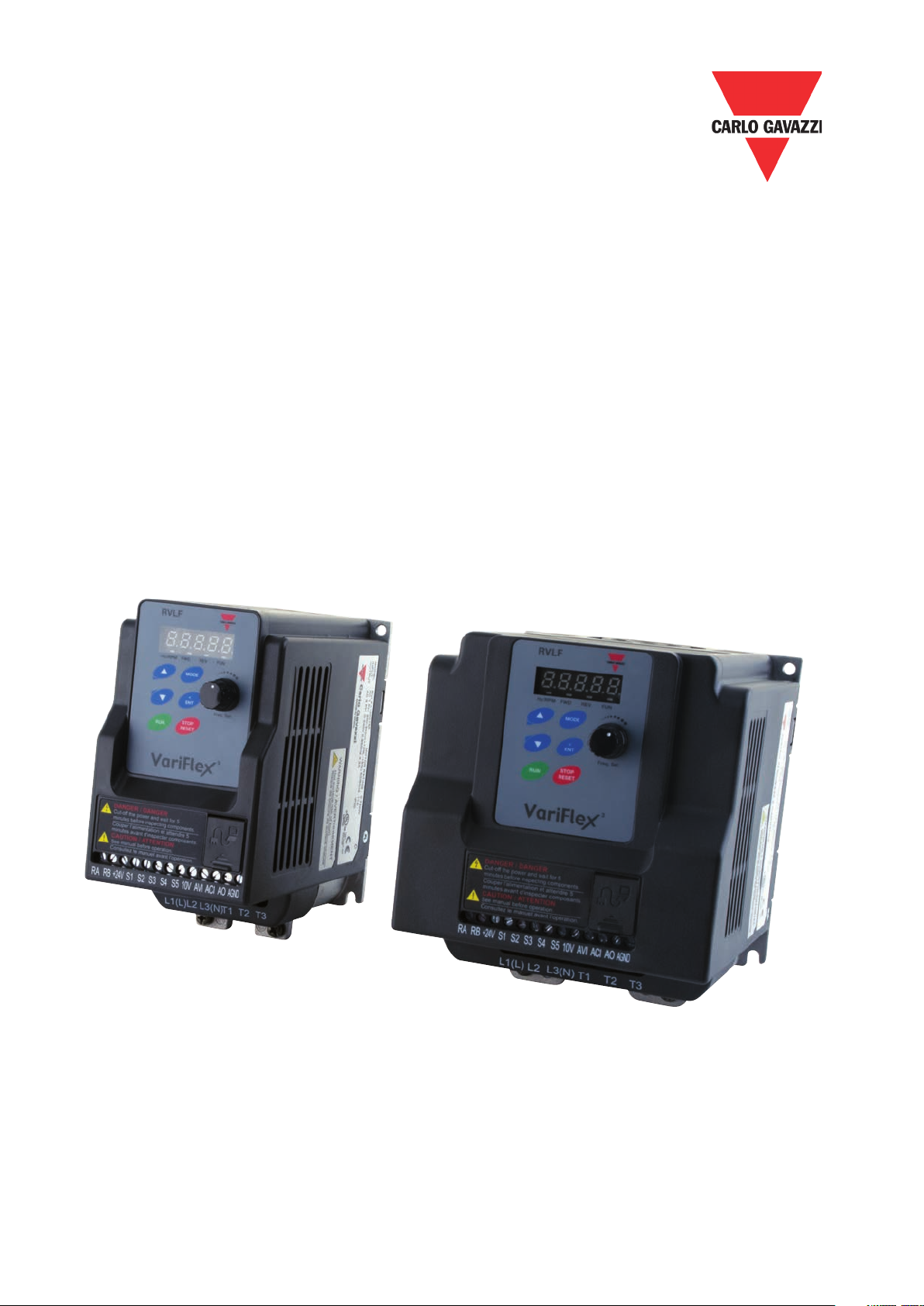
Motor Controllers AC Variable Frequency Drives Type VariFlex3 RVLF