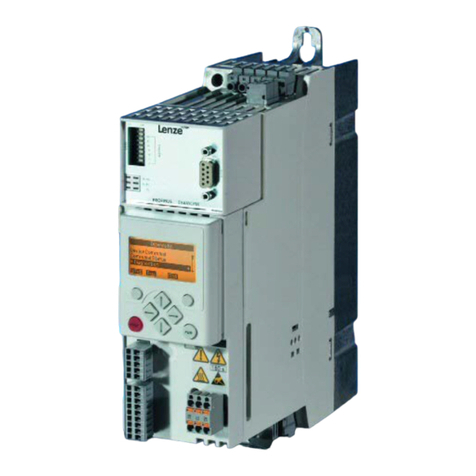
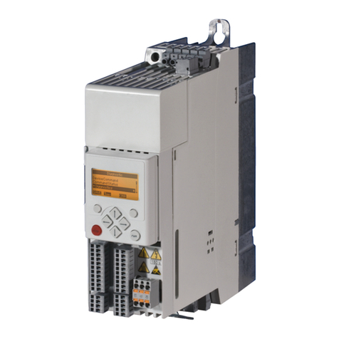
Lenze L-force 8400 BaseLine D Mounting instructions

L
EDS84AVBDxx
13292140
Ä.>6Iä
Software Manual
E84AVBDExxxxxx0
8400 BaseLine D Inverter Drives
8400
L-force Drives

8400 BaseLine D | Software Manual
Overview of the technical documentation for Inverter Drives 8400
2LFirmware 03.00 - DMS EN 5.0 - 07/2009
Overview of the technical documentation for Inverter Drives 8400
Project planning, selecting & ordering Legend:
8400 Hardware Manual Printed documentation
Catalogue Online documentation
(PDF/»Engineer« online help)
Mounting & wiring Abbreviations used
MA 8400 BaseLine/8400StateLine/HighLine BA Operating Instructions
MA for communication module KHB Communication Manual
MA for extension module MA Mounting Instructions
MA for safety module SW Software Manual
MA for accessories
Parameter setting
BA keypad
SW 8400 BaseLine C
SW 8400 BaseLine D ÍThis documentation
SW 8400 StateLine
SW 8400 HighLine
KHB for communication module
Commissioning of the drive
Commissioning guide
SW 8400 StateLine/HighLine
Chapter "Commissioning"
Chapter "Oscilloscope"
Chapter "Diagnostics & fault analysis"
Networking
KHB for communication medium used

Firmware 03.00 - DMS EN 5.0 - 07/2009 L3
8400 BaseLine D | Software Manual
Contents
Contents
1 About this documentation . . . . . . . . . . . . . . . . . . . . . . . . . . . . . . . . . . . . . . . . . . . . . . . . . . . . . . . . . 8
1.1 Document history . . . . . . . . . . . . . . . . . . . . . . . . . . . . . . . . . . . . . . . . . . . . . . . . . . . . . . . . . . . . . . . 8
1.2 Conventions used . . . . . . . . . . . . . . . . . . . . . . . . . . . . . . . . . . . . . . . . . . . . . . . . . . . . . . . . . . . . . . . 9
1.3 Terminology used . . . . . . . . . . . . . . . . . . . . . . . . . . . . . . . . . . . . . . . . . . . . . . . . . . . . . . . . . . . . . . . 9
1.4 Definition of notes used . . . . . . . . . . . . . . . . . . . . . . . . . . . . . . . . . . . . . . . . . . . . . . . . . . . . . . . . . 11
2 Product description . . . . . . . . . . . . . . . . . . . . . . . . . . . . . . . . . . . . . . . . . . . . . . . . . . . . . . . . . . . . . . . 12
2.1 Functions of the frequency inverter . . . . . . . . . . . . . . . . . . . . . . . . . . . . . . . . . . . . . . . . . . . . . . 12
2.2 Memory module . . . . . . . . . . . . . . . . . . . . . . . . . . . . . . . . . . . . . . . . . . . . . . . . . . . . . . . . . . . . . . . . 13
2.3 Communicating with the controller . . . . . . . . . . . . . . . . . . . . . . . . . . . . . . . . . . . . . . . . . . . . . . 14
2.3.1 Going online via diagnostic adapter . . . . . . . . . . . . . . . . . . . . . . . . . . . . . . . . . . . . . . 14
2.4 Internal Keypad . . . . . . . . . . . . . . . . . . . . . . . . . . . . . . . . . . . . . . . . . . . . . . . . . . . . . . . . . . . . . . . . . 18
3 Commissioning . . . . . . . . . . . . . . . . . . . . . . . . . . . . . . . . . . . . . . . . . . . . . . . . . . . . . . . . . . . . . . . . . . . 19
3.1 Before switching on . . . . . . . . . . . . . . . . . . . . . . . . . . . . . . . . . . . . . . . . . . . . . . . . . . . . . . . . . . . . . 19
3.2 Parameter setting and diagnosing directly at the controller. . . . . . . . . . . . . . . . . . . . . . . . 21
3.2.1 Menu structure. . . . . . . . . . . . . . . . . . . . . . . . . . . . . . . . . . . . . . . . . . . . . . . . . . . . . . . . . . 22
3.2.2 Diagnostics. . . . . . . . . . . . . . . . . . . . . . . . . . . . . . . . . . . . . . . . . . . . . . . . . . . . . . . . . . . . . . 23
3.2.3 Messages . . . . . . . . . . . . . . . . . . . . . . . . . . . . . . . . . . . . . . . . . . . . . . . . . . . . . . . . . . . . . . . 25
3.3 Test commissioning . . . . . . . . . . . . . . . . . . . . . . . . . . . . . . . . . . . . . . . . . . . . . . . . . . . . . . . . . . . . . 26
3.3.1 Test commissioning with keypad control. . . . . . . . . . . . . . . . . . . . . . . . . . . . . . . . . . 28
3.3.2 Test commissioning with terminal control . . . . . . . . . . . . . . . . . . . . . . . . . . . . . . . . 30
3.4 Commissioning of the drive application with the »Engineer« . . . . . . . . . . . . . . . . . . . . . . 32
3.4.1 Observe the safety measures . . . . . . . . . . . . . . . . . . . . . . . . . . . . . . . . . . . . . . . . . . . . . 33
3.4.2 Open the »Engineer« . . . . . . . . . . . . . . . . . . . . . . . . . . . . . . . . . . . . . . . . . . . . . . . . . . . . 34
3.4.3 Load the Lenze setting . . . . . . . . . . . . . . . . . . . . . . . . . . . . . . . . . . . . . . . . . . . . . . . . . . . 35
3.4.4 Make motor settings. . . . . . . . . . . . . . . . . . . . . . . . . . . . . . . . . . . . . . . . . . . . . . . . . . . . . 35
3.4.5 Select control source. . . . . . . . . . . . . . . . . . . . . . . . . . . . . . . . . . . . . . . . . . . . . . . . . . . . . 36
3.4.6 Start program . . . . . . . . . . . . . . . . . . . . . . . . . . . . . . . . . . . . . . . . . . . . . . . . . . . . . . . . . . . 38
3.4.7 Diagnostics. . . . . . . . . . . . . . . . . . . . . . . . . . . . . . . . . . . . . . . . . . . . . . . . . . . . . . . . . . . . . . 39
3.5 Password protection . . . . . . . . . . . . . . . . . . . . . . . . . . . . . . . . . . . . . . . . . . . . . . . . . . . . . . . . . . . . 40
3.5.1 Entry of a password not available yet . . . . . . . . . . . . . . . . . . . . . . . . . . . . . . . . . . . . . 41
3.5.2 Delete or change available password . . . . . . . . . . . . . . . . . . . . . . . . . . . . . . . . . . . . . 42
3.5.3 Access password-protected controller without knowing the password. . . . . . 43
3.5.4 Reach password-protected menu level with knowing the password . . . . . . . . 44

8400 BaseLine D | Software Manual
Contents
4LFirmware 03.00 - DMS EN 5.0 - 07/2009
4 Drive control (DCTRL) . . . . . . . . . . . . . . . . . . . . . . . . . . . . . . . . . . . . . . . . . . . . . . . . . . . . . . . . . . . . . . 45
4.1 Device states. . . . . . . . . . . . . . . . . . . . . . . . . . . . . . . . . . . . . . . . . . . . . . . . . . . . . . . . . . . . . . . . . . . . 46
4.1.1 "Init" state . . . . . . . . . . . . . . . . . . . . . . . . . . . . . . . . . . . . . . . . . . . . . . . . . . . . . . . . . . . . . . 47
4.1.2 "MotorIdent" status. . . . . . . . . . . . . . . . . . . . . . . . . . . . . . . . . . . . . . . . . . . . . . . . . . . . . . 48
4.1.3 "SafeTorqueOff" state. . . . . . . . . . . . . . . . . . . . . . . . . . . . . . . . . . . . . . . . . . . . . . . . . . . . 48
4.1.4 "ReadyToSwitchON" state. . . . . . . . . . . . . . . . . . . . . . . . . . . . . . . . . . . . . . . . . . . . . . . . 49
4.1.5 "SwitchedON" state. . . . . . . . . . . . . . . . . . . . . . . . . . . . . . . . . . . . . . . . . . . . . . . . . . . . . . 51
4.1.6 "OperationEnabled" state . . . . . . . . . . . . . . . . . . . . . . . . . . . . . . . . . . . . . . . . . . . . . . . . 51
4.1.7 Status display "Warning". . . . . . . . . . . . . . . . . . . . . . . . . . . . . . . . . . . . . . . . . . . . . . . . . 51
4.1.8 "Trouble" state . . . . . . . . . . . . . . . . . . . . . . . . . . . . . . . . . . . . . . . . . . . . . . . . . . . . . . . . . . 52
4.1.9 "Fault" state . . . . . . . . . . . . . . . . . . . . . . . . . . . . . . . . . . . . . . . . . . . . . . . . . . . . . . . . . . . . . 53
4.2 Controller commands . . . . . . . . . . . . . . . . . . . . . . . . . . . . . . . . . . . . . . . . . . . . . . . . . . . . . . . . . . . 54
4.2.1 General information . . . . . . . . . . . . . . . . . . . . . . . . . . . . . . . . . . . . . . . . . . . . . . . . . . . . . 54
4.2.2 Overview of device commands . . . . . . . . . . . . . . . . . . . . . . . . . . . . . . . . . . . . . . . . . . . 57
4.2.3 Status display for device command . . . . . . . . . . . . . . . . . . . . . . . . . . . . . . . . . . . . . . . 57
4.2.4 Load Lenze setting . . . . . . . . . . . . . . . . . . . . . . . . . . . . . . . . . . . . . . . . . . . . . . . . . . . . . . . 58
4.2.5 Save parameter set . . . . . . . . . . . . . . . . . . . . . . . . . . . . . . . . . . . . . . . . . . . . . . . . . . . . . . 58
4.2.6 Load parameter set . . . . . . . . . . . . . . . . . . . . . . . . . . . . . . . . . . . . . . . . . . . . . . . . . . . . . . 60
4.3 System block "LS_DriveInterface" . . . . . . . . . . . . . . . . . . . . . . . . . . . . . . . . . . . . . . . . . . . . . . . . 61
4.4 Parameter setting . . . . . . . . . . . . . . . . . . . . . . . . . . . . . . . . . . . . . . . . . . . . . . . . . . . . . . . . . . . . . . . 64
4.4.1 General information . . . . . . . . . . . . . . . . . . . . . . . . . . . . . . . . . . . . . . . . . . . . . . . . . . . . . 64
4.4.2 Saving of the parameters in the memory module. . . . . . . . . . . . . . . . . . . . . . . . . . 65
4.4.3 Handling of the memory module . . . . . . . . . . . . . . . . . . . . . . . . . . . . . . . . . . . . . . . . . 66
4.4.4 Non-volatile saving of parameters. . . . . . . . . . . . . . . . . . . . . . . . . . . . . . . . . . . . . . . . 67
4.4.5 Parameter set transfer . . . . . . . . . . . . . . . . . . . . . . . . . . . . . . . . . . . . . . . . . . . . . . . . . . . 67
4.4.6 Parameters for status display. . . . . . . . . . . . . . . . . . . . . . . . . . . . . . . . . . . . . . . . . . . . . 68
4.4.7 Set/remove controller inhibit. . . . . . . . . . . . . . . . . . . . . . . . . . . . . . . . . . . . . . . . . . . . . 68
4.5 Activate/deactivate quick stop function (QSP) . . . . . . . . . . . . . . . . . . . . . . . . . . . . . . . . . . . . 69

Firmware 03.00 - DMS EN 5.0 - 07/2009 L5
8400 BaseLine D | Software Manual
Contents
5 Motor control (MCTRL). . . . . . . . . . . . . . . . . . . . . . . . . . . . . . . . . . . . . . . . . . . . . . . . . . . . . . . . . . . . . 70
5.1 Selection of the operating mode . . . . . . . . . . . . . . . . . . . . . . . . . . . . . . . . . . . . . . . . . . . . . . . . . 71
5.1.1 V/f characteristic control. . . . . . . . . . . . . . . . . . . . . . . . . . . . . . . . . . . . . . . . . . . . . . . . . 74
5.1.1.1 Parameter setting of the V/f characteristic control. . . . . . . . . . . . . . . 76
5.1.1.2 Optimisation of the operational performance by means of slip
compensation . . . . . . . . . . . . . . . . . . . . . . . . . . . . . . . . . . . . . . . . . . . . . . .80
5.1.1.3 Optimisation of the Imax controller setting . . . . . . . . . . . . . . . . . . . . . . 82
5.1.2 Vector control . . . . . . . . . . . . . . . . . . . . . . . . . . . . . . . . . . . . . . . . . . . . . . . . . . . . . . . . . . . 83
5.1.2.1 Sensorless vector control (SLVC) . . . . . . . . . . . . . . . . . . . . . . . . . . . . . . . . 84
5.1.3 Automatic motor parameter identification. . . . . . . . . . . . . . . . . . . . . . . . . . . . . . . . 90
5.2 Motor selection . . . . . . . . . . . . . . . . . . . . . . . . . . . . . . . . . . . . . . . . . . . . . . . . . . . . . . . . . . . . . . . . . 92
5.2.1 Manual parameter setting of external motors. . . . . . . . . . . . . . . . . . . . . . . . . . . . . 93
5.3 Selection of the switching frequency . . . . . . . . . . . . . . . . . . . . . . . . . . . . . . . . . . . . . . . . . . . . . 94
5.4 Definition of current and speed limits . . . . . . . . . . . . . . . . . . . . . . . . . . . . . . . . . . . . . . . . . . . . 96
5.4.1 Definition of speed limits . . . . . . . . . . . . . . . . . . . . . . . . . . . . . . . . . . . . . . . . . . . . . . . . 96
5.4.2 Definition of current limits . . . . . . . . . . . . . . . . . . . . . . . . . . . . . . . . . . . . . . . . . . . . . . . 97
5.5 Flying restart function. . . . . . . . . . . . . . . . . . . . . . . . . . . . . . . . . . . . . . . . . . . . . . . . . . . . . . . . . . . 98
5.5.1 General information . . . . . . . . . . . . . . . . . . . . . . . . . . . . . . . . . . . . . . . . . . . . . . . . . . . . . 98
5.6 DC-injection braking . . . . . . . . . . . . . . . . . . . . . . . . . . . . . . . . . . . . . . . . . . . . . . . . . . . . . . . . . . . . 100
5.6.1 Manual DC-injection braking (DCB) . . . . . . . . . . . . . . . . . . . . . . . . . . . . . . . . . . . . . . . 101
5.6.2 Automatic DC-injection braking (Auto-DCB). . . . . . . . . . . . . . . . . . . . . . . . . . . . . . . 102
5.6.3 Oscillation damping . . . . . . . . . . . . . . . . . . . . . . . . . . . . . . . . . . . . . . . . . . . . . . . . . . . . . 104
5.7 Signal flow. . . . . . . . . . . . . . . . . . . . . . . . . . . . . . . . . . . . . . . . . . . . . . . . . . . . . . . . . . . . . . . . . . . . . . 105
5.8 System block "LS_MotorInterface" . . . . . . . . . . . . . . . . . . . . . . . . . . . . . . . . . . . . . . . . . . . . . . . 107
5.9 Monitoring functions. . . . . . . . . . . . . . . . . . . . . . . . . . . . . . . . . . . . . . . . . . . . . . . . . . . . . . . . . . . . 108
5.9.1 Motor temperature monitoring with I²xt. . . . . . . . . . . . . . . . . . . . . . . . . . . . . . . . . . 108

8400 BaseLine D | Software Manual
Contents
6LFirmware 03.00 - DMS EN 5.0 - 07/2009
6 I/O terminals . . . . . . . . . . . . . . . . . . . . . . . . . . . . . . . . . . . . . . . . . . . . . . . . . . . . . . . . . . . . . . . . . . . . . 111
6.1 Analog input. . . . . . . . . . . . . . . . . . . . . . . . . . . . . . . . . . . . . . . . . . . . . . . . . . . . . . . . . . . . . . . . . . . . 112
6.1.1 Terminal assignment/electrical data. . . . . . . . . . . . . . . . . . . . . . . . . . . . . . . . . . . . . . 113
6.1.2 Parameter setting . . . . . . . . . . . . . . . . . . . . . . . . . . . . . . . . . . . . . . . . . . . . . . . . . . . . . . . 114
6.1.3 Using the analog input as current input. . . . . . . . . . . . . . . . . . . . . . . . . . . . . . . . . . . 114
6.1.4 System block "LS_AnalogInput". . . . . . . . . . . . . . . . . . . . . . . . . . . . . . . . . . . . . . . . . . . 115
6.2 Digital inputs . . . . . . . . . . . . . . . . . . . . . . . . . . . . . . . . . . . . . . . . . . . . . . . . . . . . . . . . . . . . . . . . . . . 116
6.2.1 Terminal assignment/electrical data. . . . . . . . . . . . . . . . . . . . . . . . . . . . . . . . . . . . . . 116
6.2.2 Parameter setting . . . . . . . . . . . . . . . . . . . . . . . . . . . . . . . . . . . . . . . . . . . . . . . . . . . . . . . 116
6.2.3 System block "LS_DigitalInput" . . . . . . . . . . . . . . . . . . . . . . . . . . . . . . . . . . . . . . . . . . . 117
6.3 Digital outputs. . . . . . . . . . . . . . . . . . . . . . . . . . . . . . . . . . . . . . . . . . . . . . . . . . . . . . . . . . . . . . . . . . 118
6.3.1 Terminal assignment/electrical data. . . . . . . . . . . . . . . . . . . . . . . . . . . . . . . . . . . . . . 118
6.3.2 Parameter setting . . . . . . . . . . . . . . . . . . . . . . . . . . . . . . . . . . . . . . . . . . . . . . . . . . . . . . . 119
6.3.3 Function block "LS_DigitalOutput". . . . . . . . . . . . . . . . . . . . . . . . . . . . . . . . . . . . . . . . 119
7 Error management . . . . . . . . . . . . . . . . . . . . . . . . . . . . . . . . . . . . . . . . . . . . . . . . . . . . . . . . . . . . . . . . 120
7.1 Basics on error handling in the controller . . . . . . . . . . . . . . . . . . . . . . . . . . . . . . . . . . . . . . . . . 120
7.2 Drive diagnostics with the »Engineer«. . . . . . . . . . . . . . . . . . . . . . . . . . . . . . . . . . . . . . . . . . . . 121
7.3 Logbook . . . . . . . . . . . . . . . . . . . . . . . . . . . . . . . . . . . . . . . . . . . . . . . . . . . . . . . . . . . . . . . . . . . . . . . . 124
7.3.1 Functional description . . . . . . . . . . . . . . . . . . . . . . . . . . . . . . . . . . . . . . . . . . . . . . . . . . . 125
7.3.2 Reading out logbook entries. . . . . . . . . . . . . . . . . . . . . . . . . . . . . . . . . . . . . . . . . . . . . . 126
7.4 Monitoring . . . . . . . . . . . . . . . . . . . . . . . . . . . . . . . . . . . . . . . . . . . . . . . . . . . . . . . . . . . . . . . . . . . . . 127
7.4.1 Setting the error response. . . . . . . . . . . . . . . . . . . . . . . . . . . . . . . . . . . . . . . . . . . . . . . . 128
7.4.2 Monitoring of the device utilisation. . . . . . . . . . . . . . . . . . . . . . . . . . . . . . . . . . . . . . . 128
7.5 Error messages of the operating system . . . . . . . . . . . . . . . . . . . . . . . . . . . . . . . . . . . . . . . . . . 129
7.5.1 Error number . . . . . . . . . . . . . . . . . . . . . . . . . . . . . . . . . . . . . . . . . . . . . . . . . . . . . . . . . . . . 129
7.5.1.1 Structure of the error number (bit coding). . . . . . . . . . . . . . . . . . . . . . . 129
7.5.1.2 Error type . . . . . . . . . . . . . . . . . . . . . . . . . . . . . . . . . . . . . . . . . . . . . . . . . . . . . 129
7.5.1.3 Error subject area . . . . . . . . . . . . . . . . . . . . . . . . . . . . . . . . . . . . . . . . . . . . . . 129
7.5.1.4 Error ID. . . . . . . . . . . . . . . . . . . . . . . . . . . . . . . . . . . . . . . . . . . . . . . . . . . . . . . . 130
7.5.1.5 Example for bit coding of the error number . . . . . . . . . . . . . . . . . . . . . 130
7.5.2 Reset of error message . . . . . . . . . . . . . . . . . . . . . . . . . . . . . . . . . . . . . . . . . . . . . . . . . . . 131
7.5.3 Short overview (A-Z) . . . . . . . . . . . . . . . . . . . . . . . . . . . . . . . . . . . . . . . . . . . . . . . . . . . . . 132
7.5.4 Cause & possible remedies . . . . . . . . . . . . . . . . . . . . . . . . . . . . . . . . . . . . . . . . . . . . . . . 133
8 Drive Application . . . . . . . . . . . . . . . . . . . . . . . . . . . . . . . . . . . . . . . . . . . . . . . . . . . . . . . . . . . . . . . . . 135
8.1 Overview of the software structure of the drive application function. . . . . . . . . . . . . . . 136
8.1.1 Input and output interconnection of the drive application . . . . . . . . . . . . . . . . . 137
8.1.2 Functions of the drive application "Actuating drive - speed" . . . . . . . . . . . . . . . . 138
8.1.3 Pre-assignment of the drive application. . . . . . . . . . . . . . . . . . . . . . . . . . . . . . . . . . . 140
8.2 Interface description of the drive application . . . . . . . . . . . . . . . . . . . . . . . . . . . . . . . . . . . . . 142
Firmware 03.00 - DMS EN 5.0 - 07/2009 L7
8400 BaseLine D | Software Manual
Contents
9 Function library . . . . . . . . . . . . . . . . . . . . . . . . . . . . . . . . . . . . . . . . . . . . . . . . . . . . . . . . . . . . . . . . . . . 146
9.1 Function blocks . . . . . . . . . . . . . . . . . . . . . . . . . . . . . . . . . . . . . . . . . . . . . . . . . . . . . . . . . . . . . . . . . 146
9.1.1 L_NSet . . . . . . . . . . . . . . . . . . . . . . . . . . . . . . . . . . . . . . . . . . . . . . . . . . . . . . . . . . . . . . . . . . 146
9.1.1.1 Main setpoint path . . . . . . . . . . . . . . . . . . . . . . . . . . . . . . . . . . . . . . . . . . . . 147
9.1.1.2 JOG setpoints. . . . . . . . . . . . . . . . . . . . . . . . . . . . . . . . . . . . . . . . . . . . . . . . . . 148
9.1.1.3 Setpoint inversion . . . . . . . . . . . . . . . . . . . . . . . . . . . . . . . . . . . . . . . . . . . . . 148
9.1.1.4 Ramp function generator for the main setpoint . . . . . . . . . . . . . . . . . 149
9.1.1.5 S-shaped ramp . . . . . . . . . . . . . . . . . . . . . . . . . . . . . . . . . . . . . . . . . . . . . . . . 149
9.1.2 L_MPot . . . . . . . . . . . . . . . . . . . . . . . . . . . . . . . . . . . . . . . . . . . . . . . . . . . . . . . . . . . . . . . . . 150
9.1.2.1 Activation & control of motor potentiometer. . . . . . . . . . . . . . . . . . . . 152
9.1.2.2 Deactivation of motor potentiometer . . . . . . . . . . . . . . . . . . . . . . . . . . . 153
9.1.2.3 Save current output value after mains failure . . . . . . . . . . . . . . . . . . . 153
9.1.3 L_PCTRL . . . . . . . . . . . . . . . . . . . . . . . . . . . . . . . . . . . . . . . . . . . . . . . . . . . . . . . . . . . . . . . . . 154
9.1.3.1 Control characteristic . . . . . . . . . . . . . . . . . . . . . . . . . . . . . . . . . . . . . . . . . . 157
9.1.3.2 Ramp function generator. . . . . . . . . . . . . . . . . . . . . . . . . . . . . . . . . . . . . . . 158
9.1.3.3 Value range of the output signal. . . . . . . . . . . . . . . . . . . . . . . . . . . . . . . . 158
9.1.3.4 Evaluation of the output signal . . . . . . . . . . . . . . . . . . . . . . . . . . . . . . . . . 158
9.1.3.5 Deactivation of the process controller. . . . . . . . . . . . . . . . . . . . . . . . . . . 159
9.1.4 L_RLQ . . . . . . . . . . . . . . . . . . . . . . . . . . . . . . . . . . . . . . . . . . . . . . . . . . . . . . . . . . . . . . . . . . . 160
9.1.5 LS_DisFree . . . . . . . . . . . . . . . . . . . . . . . . . . . . . . . . . . . . . . . . . . . . . . . . . . . . . . . . . . . . . . 161
9.1.6 LS_DisFree_a . . . . . . . . . . . . . . . . . . . . . . . . . . . . . . . . . . . . . . . . . . . . . . . . . . . . . . . . . . . . 162
9.1.7 LS_DisFree_b . . . . . . . . . . . . . . . . . . . . . . . . . . . . . . . . . . . . . . . . . . . . . . . . . . . . . . . . . . . . 163
9.1.8 LS_ParFix. . . . . . . . . . . . . . . . . . . . . . . . . . . . . . . . . . . . . . . . . . . . . . . . . . . . . . . . . . . . . . . . 164
9.1.9 LS_ParFree_b. . . . . . . . . . . . . . . . . . . . . . . . . . . . . . . . . . . . . . . . . . . . . . . . . . . . . . . . . . . . 165
9.1.10 LS_ParFree_a . . . . . . . . . . . . . . . . . . . . . . . . . . . . . . . . . . . . . . . . . . . . . . . . . . . . . . . . . . . . 166
10 Parameter reference. . . . . . . . . . . . . . . . . . . . . . . . . . . . . . . . . . . . . . . . . . . . . . . . . . . . . . . . . . . . . . . 167
10.1 Structure of the parameter descriptions . . . . . . . . . . . . . . . . . . . . . . . . . . . . . . . . . . . . . . . . . . 168
10.1.1 Data type . . . . . . . . . . . . . . . . . . . . . . . . . . . . . . . . . . . . . . . . . . . . . . . . . . . . . . . . . . . . . . . 169
10.1.2 Parameters with read-only access . . . . . . . . . . . . . . . . . . . . . . . . . . . . . . . . . . . . . . . . 169
10.1.3 Parameters with write access . . . . . . . . . . . . . . . . . . . . . . . . . . . . . . . . . . . . . . . . . . . . 170
10.1.3.1 Parameters with setting range . . . . . . . . . . . . . . . . . . . . . . . . . . . . . . . . . 170
10.1.3.2 Parameters with selection list . . . . . . . . . . . . . . . . . . . . . . . . . . . . . . . . . . 170
10.1.3.3 Parameters with bit-coded setting . . . . . . . . . . . . . . . . . . . . . . . . . . . . . . 171
10.1.3.4 Parameters with subcodes . . . . . . . . . . . . . . . . . . . . . . . . . . . . . . . . . . . . . 172
10.1.4 Parameter attributes . . . . . . . . . . . . . . . . . . . . . . . . . . . . . . . . . . . . . . . . . . . . . . . . . . . . 172
10.2 Parameter list. . . . . . . . . . . . . . . . . . . . . . . . . . . . . . . . . . . . . . . . . . . . . . . . . . . . . . . . . . . . . . . . . . . 174
10.3 Table of attributes . . . . . . . . . . . . . . . . . . . . . . . . . . . . . . . . . . . . . . . . . . . . . . . . . . . . . . . . . . . . . . 219
11 Index . . . . . . . . . . . . . . . . . . . . . . . . . . . . . . . . . . . . . . . . . . . . . . . . . . . . . . . . . . . . . . . . . . . . . . . . . . . . 223
Your opinion is important to us. . . . . . . . . . . . . . . . . . . . . . . . . . . . . . . . . . . . . . . . . . . . . . . . . . . . . . . . . 227

8400 BaseLine D | Software Manual
About this documentation
Document history
8LFirmware 03.00 - DMS EN 5.0 - 07/2009
1 About this documentation
This Software Manual contains information about the parameterisation of the
8400 BaseLine D controller using the L-force »Engineer« and the keypad.
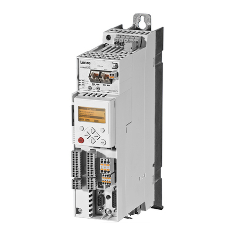
The information given in this Software Manual applies to the 8400 BaseLine D frequency
inverter with the following nameplate data:
Tip!
Current documentation and software updates for Lenze products can be found on
the Internet in the "Services & Downloads" area under
http://www.Lenze.com
1.1 Document history
Danger!
The controller is a source of danger which may lead to death or severe injury of
persons.
To protect yourself and others against these dangers, observe the safety
instructions before switching on the controller.
Please read the safety instructions provided in the 8400 Mounting Instructions
and in the 8400 Hardware Manual. Both documents are supplied with the
controller.
Type Type designation From software
version
Important
8400 BaseLine D E84AVBDExxxxSX0 2.1 Variant without digital output X4/DO1
8400 BaseLine D E84AVBDExxxxSX1 2.1 Variant with digital output X4/DO1
Digital outputs (118)
8400 BaseLine D E84AVBDExxxxxx0 3.0 New function block L_PCTRL
Version Description
1.0 06/2008 TD06 First edition
2.0 07/2008 TD 06 Second edition
3.0 02/2009 TD 06 New: The chapters "Commissioning" and "Parameter reference" have been revised,
new block L_RLQ (CW/CCW rotation)
4.0 04/2009 TD 06 New: Subcode c012 in C002 for adaption of parameter sets from controllers with
firmware version ≤V2.1 in the event of service.
5.0 04/2009 TD 06 New:
• Function block L_PCTRL
• Quick saving at the push of a button (59)
• Parameter list with info texts

Firmware 03.00 - DMS EN 5.0 - 07/2009 L9
8400 BaseLine D | Software Manual
About this documentation
Conventions used
1.2 Conventions used
This Software Manual uses the following conventions to distinguish between different
types of information:
1.3 Terminology used
Type of information Writing Examples/notes
Variable identifier Italics By setting bEnable to TRUE...
Window The Message window... / The Options dialog box...
Control element Bold The OK button... / The Copy command... / The Properties tab... / The
Name input field...
Sequence of
menu commands
If several commands must be used in sequence to carry out a function,
then the individual commands are separated by an arrow: Select
FileOpen to...
Shortcut <Bold> Press <F1> to open the Online Help.
If a command requires a combination of keys, a "+" is placed between
the key symbols: Use <Shift>+<ESC> to...
Hyperlink Underlined A hyperlink is an optically highlighted reference which is activated by a
mouse click.
Step-by-step
instructions Step-by-step instructions are indicated by a pictograph.
Term Meaning
»Engineer« Lenze PC software which supports you in "engineering" (parameterisation,
diagnostics and configuration) throughout the whole life cycle, i.e. from
planning to maintenance of the commissioned machine.
Application block Block for a drive application (e.g. actuating drive - speed)
A drive application is a drive solution provided with the experiences and
know-how of Lenze in which function blocks interconnected to a signal flow
form the basis for implementing typical drive tasks.
Code Parameter used for controller parameter setting or monitoring.
The term is usually called "index".
Display codes Parameter that displays the current status or value of a system block input/
output.
FB Editor Function block editor
Graphical interconnection tool which is provided for signal interconnections
in the »Engineer« on the FB editor tab and by means of which the
applications integrated in the drive can also be reconfigured and extended
by individual functions.
Function block A function block can be compared with an integrated circuit that contains a
certain control logic and delivers one or several values when being executed.
• Each function block has a unique identifier (the instance name) and a
processing number which defines the position at which the function
block is calculated during the task cycle.
Lenze setting This setting is the default factory setting of the device.
Port block Block for implementing the process data transfer via a fieldbus
QSP Quick stop
SC Operating mode: Servo Control
SLVC Operating mode: SensorLess Vector Control

8400 BaseLine D | Software Manual
About this documentation
Terminology used
10 LFirmware 03.00 - DMS EN 5.0 - 07/2009
Subcode If a code contains several parameters, the individual parameters are stored
under "subcodes".
This manual uses a slash "/" as a separator between code and subcode
(e.g. "C118/3").
The term is usually called "subindex".
System block System blocks provide interfaces to basic functions and to the hardware of
the controller in the FB editor of the »Engineer« (e.g. to the digital inputs).
VFCplus Operating mode: V/f characteristic control ("Voltage Frequency Control")
Term Meaning

Firmware 03.00 - DMS EN 5.0 - 07/2009 L11
8400 BaseLine D | Software Manual
About this documentation
Definition of notes used
1.4 Definition of notes used
The following signal words and symbols are used in this Software Manual to indicate
dangers and important information:
Safety instructions
Layout of the safety instructions:
Application notes
Pictograph and signal word!
(characterise the type and severity of danger)
Note
(describes the danger and informs how to prevent dangerous situations)
Pictograph Signal word Meaning
Danger! Danger of personal injury through dangerous electrical voltage
Reference to an imminent danger that may result in death or serious personal injury
if the corresponding measures are not taken.
Danger! Danger of personal injury through a general source of danger
Reference to an imminent danger that may result in death or serious personal injury
if the corresponding measures are not taken.
Stop! Danger of property damage
Reference to a possible danger that may result in property damage if the
corresponding measures are not taken.
Pictograph Signal word Meaning
Note! Important note to ensure trouble-free operation
Tip! Useful tip for easy handling

8400 BaseLine D | Software Manual
Product description
Functions of the frequency inverter
12 LFirmware 03.00 - DMS EN 5.0 - 07/2009
2 Product description
2.1 Functions of the frequency inverter
Memory module for parameter transfer and quick and easy device replacement
Approved for use in balanced supply systems (TN systems)
Wide input voltage range up to 500V (+10%) for a worldwide application without using
additional transformers
Approvals CE, UL
High overload capacity up to 200% for generating high breakaway torques and for a
fault-tolerant operation
Integrated brake transistor (brake chopper) only available with devices operating at
400 V / 500 V.
Integrated interface for diagnostics via PC with extensive diagnostic options
Integrated protective functions
Adjustable warning levels for a simplified and safe machine maintenance (e.g. motor
operating time)
Adjustable password to protect your parameter setting
Saving of all parameters at the push of a button
Relay output
DC connection
Integrated EMC shield connections for control cables

Firmware 03.00 - DMS EN 5.0 - 07/2009 L13
8400 BaseLine D | Software Manual
Product description
Memory module
2.2 Memory module
The memory module is a memory location for the drive parameters of the 8400 BaseLine.
The pluggable design especially serves to
restore an application after a device has been exchanged.
duplicate identical drive tasks within the 8400 BaseLine frequency inverter series.
Tip!
For duplication, we recommend to use the optionally available EPM Programmer.
Exchange of the memory module
By default, the memory module is positioned in the EPM slot at the front of the controller
(see arrow).
To avoid confusion with other Lenze products, the memory modules of the 8400 BaseLine
frequency inverter series are grey. The exchange of these memory modules among each
other is possible without any problems.
More details on the handling can be found in the 8400 hardware manual which is part of
the data medium included in the scope of supply.
[2-1] Positioning of the grey memory module at the front of the 8400 BaseLine
Danger!
After switching off the mains, wait three minutes before working on the
controller. If you want to remove the memory module, make sure that the
controller is deenergised.

8400 BaseLine D | Software Manual
Product description
Communicating with the controller
14 LFirmware 03.00 - DMS EN 5.0 - 07/2009
2.3 Communicating with the controller
The following interface can be used to build up communication between PC and controller:
Diagnostic interface X6/Going online via diagnostic adapter
2.3.1 Going online via diagnostic adapter
For the initial commissioning of the controller, you can use, for instance, the diagnostic
adapter offered by Lenze:
Note!
Please observe the documentation for the diagnostic adapter!

Firmware 03.00 - DMS EN 5.0 - 07/2009 L15
8400 BaseLine D | Software Manual
Product description
Communicating with the controller
Preconditions:
The diagnostic adapter is connected to diagnostic interface X6 on the controller and to
a free USB port on the PC.
The driver required for the diagnostic adapter is installed.
The controller is supplied with mains power via X100.
How to build up an online connection via the diagnostic adapter:
1. Select the 8400 BaseLine controller to which you want to build up an online
connection in the Project view of the »Engineer«:
2. Click the icon or select the command OnlineGo online.
• If no online connection has been configured for the selected controller so far,
the Device assignment offline devices dialog box will be displayed:
• The dialog box also appears if the online connection is built up via the command
OnlineGo online instead of using the toolbar icon.
3. Select the "Diagnostic adapter" entry from the Bus connection list field.
Stop!
If you change parameters in the »Engineer« while the controller is connected
online, the changes will be directly accepted by the controller!

8400 BaseLine D | Software Manual
Product description
Communicating with the controller
16 LFirmware 03.00 - DMS EN 5.0 - 07/2009
4. Click Find device access path to find the controller in the selected bus system.
•TheAddress assignment dialog box appears:
5. Select the corresponding controller from the Field devices located list field.
6. Click OK.
•TheAddress assignment dialog box is closed and the selected Device access path
(e.g. "DDCMP:/") is indicated in the Device assignment offline devices dialog box.
7. Click Connect.
• The dialog box is closed and the online connection with the controller is built up.
• When an online connection with the controller exists, this is indicated in the
Project view - by a yellow icon and
- by the word "ONLINE" in the status bar:
Now you can use the icons and to easily build up and end a connection with the
controller. The communication settings are only required when communication with a
controller is built up for the first time.
If you want to change the existing configuration, select the command OnlineGo
online to open the Device assignment offline devices dialog box and change the settings.
With an online connection, the »Engineer« displays the current parameter settings of
the controller with a yellow background colour.

Firmware 03.00 - DMS EN 5.0 - 07/2009 L17
8400 BaseLine D | Software Manual
Product description
Communicating with the controller
When the background colour changes from yellow to red, the connection with the
controller has been interrupted.

8400 BaseLine D | Software Manual
Product description
Internal Keypad
18 LFirmware 03.00 - DMS EN 5.0 - 07/2009
2.4 Internal Keypad
Display elements and control panel
Symbol Information Meaning
c4-character display with LEDs (A ... F)
A orange Set current/torque limit is reached
B yellow Minus sign for identifying the negative numbers with more than 3 digits.
C yellow User-LED, can be configured via C621/42
D red See Signalling of the LEDs "D" and "E" (24)
E green
F yellow Direction of rotation, CCW rotation
Off Rotational direction CW
blinking Commanded direction does not (yet) equal the actual direction - for example
during reversing
ESC Escape key back
↵Enter key Short: Next / confirmation
3 seconds: Save all parameters
Navigation key,
upwards
Short:
Navigation in the menu level and parameter level and parameter editing
Long (> 2 seconds):
Fast scrolling function
Navigation key,
downwards
8888
B
ESC
C
D
E
F
A
1

Firmware 03.00 - DMS EN 5.0 - 07/2009 L19
8400 BaseLine D | Software Manual
Commissioning
Before switching on
3 Commissioning
3.1 Before switching on
In order to prevent injury to persons or damage to material assets, check
before connecting the mains voltage:
– Wiring for completeness, short circuit, and earth fault
– The "emergency stop" function of the entire system
– The motor circuit configuration (star/delta) must be adapted to the output voltage
of the controller
– The in-phase connection of the motor
the setting of the most important drive parameters before enabling the controller:
– Is the V/f rated frequency adapted to the motor circuit configuration?
– Are the drive parameters relevant for your application set correctly?
– Is the configuration of the analog and digital inputs and outputs adapted to the
wiring?
Danger!
• Continuous operation at low field frequency with rated motor current may
lead to thermal overload when self-ventilated machines are used. If required,
motor temperature monitoring should be activated with C120
Motor temperature monitoring with I²xt (108).
• If an asynchronous motor with the nameplate data 400 V /230 V is delta-
connected to a frequency inverter for 400 V mains supply voltage, set code
C015 (V/f base frequency) to 87 Hz.

8400 BaseLine D | Software Manual
Commissioning
Before switching on
20 LFirmware 03.00 - DMS EN 5.0 - 07/2009
Tip!
In the Lenze setting, the "linear V/f characteristic" mode is set as motor control. The
parameter settings are preset so that, if the frequency inverter and the 50 Hz
asynchronous machine match in terms of power, the controller is immediately
ready for operation without any further parameter setting expense and the motor
operates satisfactorily.
Recommendations for the following application cases:
• If the frequency inverter and the motor differ widely in terms of power, set
Imax ( C022) to 2.0 IN(motor).
• If a high starting torque is required
set Vmin boost ( C016) in motor idle state so that the rated motor current (
C058) flows at a field frequency of f = 3Hz.
• For noise optimisation
set the switching frequency ( C018) to "3" (16 kHzsin var).
• If you need a high torque at low speed we recommend the control mode “vector
control".
Table of contents
Other Lenze Inverter Drive manuals

Lenze
Lenze 8600 series Parts list manual

Lenze
Lenze 8400 StateLine C User manual

Lenze
Lenze L-force 8400 Series User manual

Lenze
Lenze 8300-A Series Parts list manual

Lenze
Lenze 630 Series Operating instructions

Lenze
Lenze 8400 HighLine C Series Mounting instructions

Lenze
Lenze 8300 Series Parts list manual

Lenze
Lenze 8400 motec Series User manual

Lenze
Lenze L-force 8400 Series User manual

Lenze
Lenze 8400 motec Series User manual