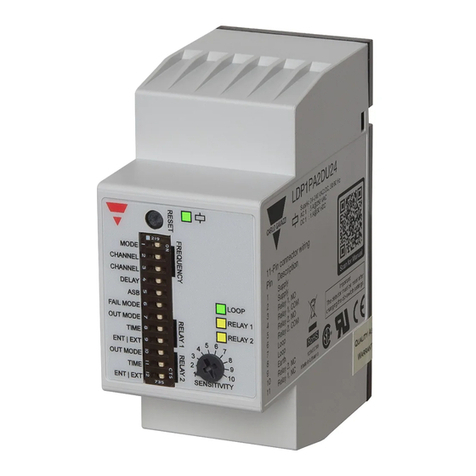
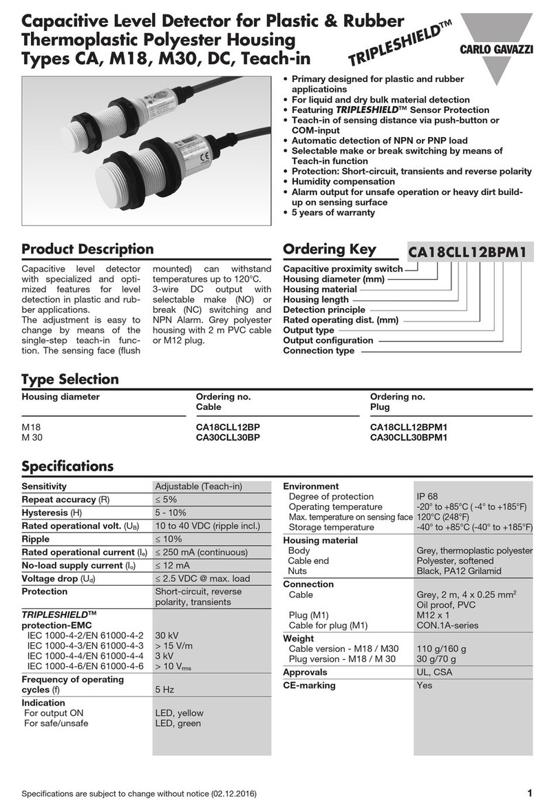
CARLO GAVAZZI LDP1 User manual

Loop Detector
Single and Dual Loops
Plug In
Carlo Gavazzi Industri Over Hadstenvej 40, 8340 Hadsten, Denmark
Instruction manual
Manuel d’instructions
Manuale d’istruzione
Betriebsanleitung
Manual de instrucciones
Brugervejledning
使用手册
LDP1, LDP2

ENGLISH page.......................3
DEUTSCH seite ....................32
FRANÇAIS page ..................62
ESPAÑOL página .................92
ITALIANO pagina...............122
DANSK side ......................152
中文 第页 .........................182

Rev.00 - 09.2018 | LDP1/LDP2 Single and Dual Loop Detector | © 2018 | CARLO GAVAZZI Industri
3
EN
Table of contents
1. Introduction .............................................................................................................. 4
1.1 Description ..........................................................................................................................4
1.2 Validity of documentation ......................................................................................................4
1.3 Who should use this documentation........................................................................................4
1.4 Use of the product ................................................................................................................4
1.5 Safety precautions................................................................................................................4
1.6 Other documents..................................................................................................................4
1.7 Acronyms............................................................................................................................5
2. Product ..................................................................................................................... 6
2.1 Main features.......................................................................................................................6
2.2 Identification number ............................................................................................................6
2.3 Operating modes .................................................................................................................7
2.3.1 SIO mode.........................................................................................................................7
2.3.2 IO-Link mode ....................................................................................................................7
2.4 Output Parameters................................................................................................................8
2.4.1 Sensor front ......................................................................................................................8
2.4.2 Input selector ..................................................................................................................11
2.4.3 Logic function block .........................................................................................................11
2.4.4 Timer (Can be set individually for Out1 and Out2) ..............................................................13
2.4.5 Output Inverter................................................................................................................16
2.4.6 Output stage mode..........................................................................................................16
2.5 Teach procedure ................................................................................................................17
2.5.1 External Teach (Teach-by-wire)...........................................................................................17
2.5.2 Teach from IO-Link Master ................................................................................................17
2.6 Sensor Specific adjustable parameters .................................................................................20
2.6.1 Selection of local or remote adjustment ..............................................................................20
2.6.2 Process data and variables...............................................................................................20
2.6.3 Sensor application setting.................................................................................................20
2.6.4 Temperature alarm threshold.............................................................................................20
2.6.5 Safe limits.......................................................................................................................21
2.6.6 Event configuration..........................................................................................................21
2.6.7 Quality of run QoR..........................................................................................................21
2.6.8 Quality of Teach QoT.......................................................................................................22
2.6.9 Detection Filter ................................................................................................................22
2.6.10 LED activation ...............................................................................................................22
2.7 Diagnostic parameters ........................................................................................................23
3. Wiring diagrams..................................................................................................... 24
4. Commissioning........................................................................................................ 24
5. Operation ............................................................................................................... 25
6. IODD file and factory setting ................................................................................... 26
6.1 IODD file of an IO-Link device..............................................................................................26
6.2 Factory setting ...................................................................................................................26
7. Appendix................................................................................................................ 26
7.1 Acronyms..........................................................................................................................26
7.2 IO-Link Device Parameters for CA18CA.. and CA30CA..........................................................27
7.2.1 Device parameters...........................................................................................................27
7.2.2 SSC parameters ..............................................................................................................28
7.2.3 Output Parameters...........................................................................................................29
7.2.4 Sensor specific adjustable parameters................................................................................30
7.2.5 Diagnostic parameters .....................................................................................................31
Dimensions ................................................................................................................. 212
Mounting .................................................................................................................... 212
Detection stability ....................................................................................................... 213
Installation hints ......................................................................................................... 214
Rev.00 - 09.2018 | LDP1/LDP2 Single and Dual Loop Detector | © 2018 | CARLO GAVAZZI Industri
4
EN
1. Introduction
This manual is a reference guide for Carlo Gavazzi loop detector LDP1 and LDP2. It describes the product
specifications as well as how to install, set up and use the product for its intended use.
1.2 Validity of documentation
This manual is valid only for LDP1 and LDP2 Loop detector and until any newer documentation is published.
This instruction manual describes the functions, operations and installation of the product for its intended
use.
1.6 Other documents
It is possible to find the datasheet, manuals, brochures and electrical drawings on the Internet at
http://gavazziautomation.com
1.5 Safety precautions
This loop detector must not be used in applications where personal safety depends on the function of the loop
detector (The loop detector is not designed according to the EU Machinery Directive).
Installation and use must be carried out by trained technical personnel with basic electrical installation knowledge.
The installer is responsible for correct installation according to local safety regulations and must ensure that a
defective loop detector will not result in any hazard to people or equipment. If the loop detector is defective, it
must be replaced and secured against unauthorized use.
1.3 Who should use this documentation
This manual contains important information regarding installation and must be read and completely
understood by specialized personnel dealing with these kinds of devices.
We highly recommend that you read the manual carefully before installing the loop detector. Please save
the manual for future use. The installation manual is intended solely for qualified technical personnel.
1.4 Use of the product
Loop detector is primarily used to detect vehicles such as cars, trucks, buses and others.
A loop on the ground is required for the loop detector to detect any vehicles above the loop. The device
works on the same principle of an inductive sensor; utilizing the phenomenon of eddy current. When a
metal target/vehicle approaches on top of the loop, the magnetic field generated by the loop interacts with
the target and make the loop detector to change its status.
Loop detector can be used in carpark barriers, bollards, gates, toll gantries and many other door access
applications.
1.1 Description
Carlo Gavazzi loop detector are devices designed and manufactured in accordance with IEC international
standards and are subject to the Low Voltage (2014/35/EU) and Electromagnetic Compatibility (2014/30/
EU) EC directives.
All rights to this document are reserved by Carlo Gavazzi Industri: copies may be made for internal use
only.
Please do not hesitate informing us to make any suggestions for improving this document.

Rev.00 - 09.2018 | LDP1/LDP2 Single and Dual Loop Detector | © 2018 | CARLO GAVAZZI Industri
5
EN
1.7 Acronyms
I/O Input/Output
PD Process Data
PLC Programmable Locic Controller
SIO Standard Input Output
SP Setpoints
IODD I/O Device Description
IEC International Electrotechnical Commission
NO Normally Open contact
NC Normally Closed contact
NPN Pull load to ground
PNP Pull load to V+
Push-Pull Pull load to ground or V+
QoR Quality of Run
QoT Quality of Teach
UART Universal Asynchronous Receiver-Transmitter
SO Switching Output
SSC Switching Signal Channel

Rev.00 - 09.2018 | LDP1/LDP2 Single and Dual Loop Detector | © 2018 | CARLO GAVAZZI Industri
6
EN
2. Product
2.1 Main features
• Loop input inductance: 20 μH to 1000 μH
• Adjustable sensitivity in 10 steps: 0.01% to 1.00% via potentiometer
• Automatic loop frequency tuning or manual tuning
• 4 adjustable loop frequency channels to avoid crosstalk
• Automatic Sensitivity Boost (ASB) for high bed vehicle detection
• Fail safe and fail secure mode is selectable
• 2 x SPDT relay outputs, selectable operation as pulse or presence switching
• Multicolor power/fault LED indication for easy setup and intuitive diagnostic
• Individual loop state multicolor LED to indicate different loop status and fault.
• Loop diagnostic capability: loop short circuit, loop open circuit, inductance out of range,
channels crosstalk.
• Directional logic for dual loop.
• Wide range power supply: 24-240 VAC/VDC, 45-65 Hz
2.2 Identification number
Code Option Description
L-Loop
D-Detector
P-Plug in
1/2 1Single Loop
2Dual Loop
P-Potentiometer
A-Adjustment
2-Number of outputs
D-2 x SPDT outputs
U24 -Power supply 24 - 240 VAC/VDC
Number of loops Code
1 LDP1PA2DU24
2 LDP2PA2DU24-

Rev.00 - 09.2018 | LDP1/LDP2 Single and Dual Loop Detector | © 2018 | CARLO GAVAZZI Industri
7
EN
2.3 Specifications
Loop input inductance 20 μH ... 1000 μH
Adjustable sensitivity 0,01% ... 1,00%
Number of adjustable steps 10
Number of frequency channels 4
Frequency range 10 ... 130 kHz
Loop fault detection Short circuit, open circuit, inductance out of range,
frequency crosstalk
Response time 130 ms
Output type Relay
No of output 2 x SPDT
Output mode Pulse or presence; selectable via dip switch
Output Assignment LDP1: 2 x SPDT for loop 1
LDP2: 1 x SPDT for loop 1 and 1 x SPDT for loop 2
Rated operational voltage 250 VAC/VDC
Rated operational current (Ie) AC1: 5 A @ 250 VAC
DC1: 1 A @ 30 VDC
Mechanical lifetime 15 x 106
Electrical lifetime >100 000 operations (@5A load)
Protection Reverse polarity and transients
Rated operational voltage (UB) 24 ... 240 VAC/VDC
LDP1 Power consumption 24 VAC/VDC < 2 W / 3.5 VA
115 VAC/VDC < 2 W / 6 VA
240 VAC/VDC < 2.5 W / 7 VA
LDP2 Power consumption 24 VAC/VDC < 2.5 W / 4 VA
115 VAC/VDC < 2.5 W / 7 VA
240 VAC/VDC < 3 W / 8 VA
Rated supply frequency 45 to 65 Hz
Rated insulation voltage 800 V
Rated impulse withstand voltage 4 kV (1.2/50 μs)
Power-ON delay (tv) 5 seconds
Protection Reverse polarity, transients
Ambient temperature -40° ... +70°C (-40° ... +158°F) (operating)
-40° ... +70°C (-40° ... +158°F) (storage)
Ambient humidity range 0% ... 90% (operating)
0% ... 90% (storage)
Overvoltage category III (IEC)
Degree of protection IP30 (IEC)
Pollution degree 2 (IEC)
Connection type 11 pin circular plug-in
Connection at socket (ZPD11A) Screw terminal
Housing material PPO PX9406-802, PPO Noryl SE1
Colour RAL 7035 (Grey)
Dimensions 81mm (h) x 35.5mm (w) x 60.2mm (d)
Weight LDP1: 105 g
LDP2: 108g

Rev.00 - 09.2018 | LDP1/LDP2 Single and Dual Loop Detector | © 2018 | CARLO GAVAZZI Industri
8
EN
LDP plug in version required to be plugged into a socket ZPD11A which is sold separately.
3. Wiring diagrams
Single loop (LDP1) plug configuration
1
2
3
4
567
8
9
10
11
Supply
Loop
Relay
1
Relay 2
1Supply
2Supply
3Relay 1 (N.O.)
4Relay 1 (COM)
5Relay 2 (N.O.)
6Relay 2 (COM)
7Loop
8Loop
9Earth
10 Relay 2 (N.C.)
11 Relay 1 (N.C.)
Earth pin must be connected to earth
Do not wipe grease off pins
Dual loop (LDP2) plug configuration
1
2
3
4
567
8
9
10
11
Supply
Loop 1
Relay
1
Relay 2
Loop 2
1Supply
2Supply
3Relay 1 (N.O.)
4Relay 1 (COM)
5Relay 2 (N.O.)
6Relay 2 (COM)
7Loop 1
8Loop 1, 2, Earth
9Loop 2
10 Relay 2 (N.C.)
11 Relay 1 (N.C.)
Earth pin must be connected to earth
Do not wipe grease off pins

Rev.00 - 09.2018 | LDP1/LDP2 Single and Dual Loop Detector | © 2018 | CARLO GAVAZZI Industri
9
EN
4. Structure
Loop 2 LED
Relay 2 LED
Power / Fault LED
Reset button
Loop LED
Relay 1 LED
Relay 2 LED
Dip switch
Potentiometer
LDP1 Single Loop
Power / Fault LED
Reset button
Potentiometer loop 2
Loop 1 LED
Relay 2 LED
Dip switch
Potentiometer loop 1
LDP2 Dual Loop

Rev.00 - 09.2018 | LDP1/LDP2 Single and Dual Loop Detector | © 2018 | CARLO GAVAZZI Industri
10
EN
Loop state LED
LED colour LED constant LED Flashing (3 Hz)
Inductance OK -
Inductance too high Inductance too low
Loop is open circuit Loop is short circuit
Relay state LED
LED colour Mode Relay
deactivated Relay activated
Presence mode OFF ON
Pulse mode, 0.1 s OFF Flashing 0.5 s
Pulse mode, 0.5 s OFF Flashing 1.0 s
Power / fault indicator
LED colour LED constant LED Flashing (1 Hz)
All OK (ASB OFF) DIP switch changed, but
product not reset
Low signal indication -
Channel crosstalk -
ASB ON indication -
5. LED indications
In general, LDP loop detectors have 3 categories of LED indications; namely Power/Fault indicator
LED, Loop state LED and Relay state LED:
Single loop (LDP1)
Loop state LED
LED colour LED constant LED Flashing (3 Hz)
Inductance OK -
Inductance too high Inductance too low
Loop is open circuit Loop is short circuit
Relay state LED
LED colour Mode Relay
deactivated Relay activated
Presence mode OFF ON
Pulse mode, 0.1 s OFF Flashing 0.5 s
Pulse mode, 0.5 s OFF Flashing 1.0 s
Power / fault indicator
LED colour LED constant LED Flashing (1 Hz)
All OK (ASB OFF) DIP switch changed, but
product not reset
Low signal indication -
Channel crosstalk -
ASB ON indication -
Dual loop (LDP2)

Rev.00 - 09.2018 | LDP1/LDP2 Single and Dual Loop Detector | © 2018 | CARLO GAVAZZI Industri
11
ENEN
5.1 Power / fault indicator LED
LED colour LED constant LED Flashing (1 Hz)
All OK (ASB OFF) DIP switch changed, but
product not reset
Low signal indication -
Channel crosstalk -
ASB ON indication -
Explanation:
1. Green LED (steady): Unit is powered up and everything is working well.
2. Green LED (blinking): Dip switch has been changed since last power up and Loop Detector has not
been reset yet. Please press the reset button.
3. Yellow LED (steady): Signal level is low in the loop.
4. Red LED (steady): Crosstalk of loop frequency with another loop detected. Select different frequency
channel on DIP switches and reset product.
5. Blue LED (steady): Automatic Sensitivity Boost is turned ON and everything is working well
5.2 Loop state LED
Explanation:
1. Green LED (steady): Loop inductance is within limit and working well
2. Yellow LED (steady): Loop inductance is too high (more than working range 1000µH)
3. Yellow LED (blinking): Loop inductance is too low (less than working range 20µH)
4. Red LED (steady): Loop is open circuit
5. Red LED (blinking): Loop is short circuit
LED colour LED constant LED Flashing (3 Hz)
Inductance OK -
Inductance too high Inductance too low
Loop is open circuit Loop is short circuit
5.3 Relay state LED
Explanation:
1. Yellow LED (off): Relay is not activated
2. Yellow LED (steady): Relay is activated and in presence mode
3. Yellow LED (Flashing 0.5 s): Relay is activated and in pulse mode, 0.1 s
4. Yellow LED (Flashing 1.0 s): Relay is activated and in pulse mode, 0.5 s
LED colour Mode Relay deactivated Relay activated
Presence mode OFF ON
Pulse mode, 0.1 s OFF Flashing 0.5 s
Pulse mode, 0.5 s OFF Flashing 1.0 s

Rev.00 - 09.2018 | LDP1/LDP2 Single and Dual Loop Detector | © 2018 | CARLO GAVAZZI Industri
12
EN
6. Dip Switch
DIP Switch settings for Single Loop (LDP1)
123456789101112
ON
ON
DIP-switch 1 - Selection mode: The loop detector operates on one out of four channels.
Depending on the noise sources in the vicinity (other loop detectors/frequency converters/starters
etc. i.e. crosstalk) can it be helpful to choose a channel where the loop detector is not disturbed by
the noise. The loop detector will indicate by a white flash which channel the loop detector are using
after power up.
Set DIP SWITCH 1 to OFF for automatically selection During startup will the loop detector
measure the noise levels on all channels and automatically select the channel with the least noise. This
will be done once every time the loop detector is powered up.
Set DIP SWITCH 1 to ON for manual selection Use dip switch 2 and 3 for selecting channel 1
,2 ,3 or 4.
Frequency settings
1Selection
mode Automatic channel selection Manual channel selection
2Channel
selection DIP switch 2 and 3 are not used in
automatic channel selection
1 2 3 4
3
General settings
4 Turn-on delay Delay OFF Delay 2.0 sec
5 ASB ASB OFF ASB ON
6 Failure mode Fail safe Fail secure
Relay 1 settings
7 Output mode Pulse mode Presence mode
8 Time 0.1 sec pulse 0.5 sec pulse Infinite 60 min 10 min 1 min
9 Entry / Exit Vehicle entry Vehicle exit
Relay 2 settings
10 Output mode Pulse mode Presence mode
11 Time 0.1 sec pulse 0.5 sec pulse Infinite 60 min 10 min 1 min
12 Entry / Exit Vehicle entry Vehicle exit

Rev.00 - 09.2018 | LDP1/LDP2 Single and Dual Loop Detector | © 2018 | CARLO GAVAZZI Industri
13
EN
Dip-switch 2 & 3 - Channel selection: Only used when dip switch 1 is set to “Manual”. Not
used if dip switch 1 is set to “Auto”.
Select the loop operating frequency by using the combination below:
(Switch 4) Delay: To prevent false and unintentional detections of objects moving nearby to the
loop, the loop turn on delay time can be prolonged to 2 seconds. This is to ensure a stable detection
before a valid detection signal is accepted. Default detection time is 0.1 second (100ms)
(Switch 5) ASB: In installation whereby there is high bed vehicles (i.e. trucks, lorry, tractors);
Automatic Sensing Boost (ASB) function can boost the loop sensitivity during detection. This ensures
high bed vehicles will be detected correctly. Using this switch 5, ASB can be turned on or off.
(Switch 6) Fail Mode: Selecting “Fail Safe” will ensure that during power loss to the loop detector,
the relay contacts will activate (energized) and hence resulting the barrier to open. This is preferred
in application whereby during power loss, it is preferred to open the barrier such as in public areas,
shopping malls etc.
While selecting “Fail Secure” will ensure that during power loss to the loop detector, the relay
contacts will remain deactivated (deenergized) and hence resulting the barrier to close. This is useful
in application whereby during power loss, it is preferred to close the barrier such as in private areas,
private apartments etc.
Note: The fail safe and fail secure mentioned above is only referring to the power loss to the loop
detector and not referring to the power loss of the main source or power loss to the barrier. This is
because power is still required for the barrier to open or close regardless. If the same power source
is used for loop detector and barrier, a kind of backup power is then required.
(Switch 7) (Switch 10) Out Mode: Relay output 1 and relay output 2 can be independently set
to be in pulse mode or presence mode.
In pulse mode, the relay only activates only for a short period when the vehicle enters or exits the loop.
In presence mode, the relay will remain activated as long as there is a vehicle parked on the loop.
Switch 7 is for relay 1 and switch 10 is for relay 2.
(Switch 8) (Switch 11) Time: If pulse mode is selected in switch 7 or switch 10, the pulse output
duration can be set to be 0.1 second or 0.5 second duration.
Switch 8 is for relay 1 and switch 11 is for relay 2.
(Switch 9) (Switch 12) Ent|Ext: If pulse mode is selected in switch 7 or switch 10, the pulse
output can set to be activated when vehicle enters the loop or only when the vehicle exits the loop.
Switch 9 is for relay 1 and switch 12 is for relay 2.
If presence mode is selected in switch 7 or switch 10, then switch 8/9 (relay 1) and switch 11/12
(relay 2) will change functionality.
In Presence mode, switch 8/9 (relay 1) and switch 11/12 (relay 2) are then used to set the maximum
time of an activation. If setting is different from infinite, the relay output will deactivate after the
specified time, following the table here:

Rev.00 - 09.2018 | LDP1/LDP2 Single and Dual Loop Detector | © 2018 | CARLO GAVAZZI Industri
14
EN
DIP Switch settings for Dual Loop (LDP2)
123456789101112
ON
ON
Bit 1 setting Bit 2 setting Output Presence Time
0 0 Infinity
0 1 1 hour
1 0 10 minutes
1 1 1 minute
In infinite, the relay will continue to be activated as long as the vehicle is still on the loop.
Frequency settings
1Selection
mode Automatic channel selection Manual channel selection
2Channel
selection DIP switch 2 and 3 are not used in
automatic channel selection
1 2 3 4
3
General settings
4 Turn-on delay Delay OFF Delay 2.0 sec
5 ASB ASB OFF ASB ON
6 Failure mode Fail safe Fail secure
Relay 1 settings
7 Output mode Pulse mode Presence mode
8 Mode select Vehicle entry Vehicle exit Innite 1 m
Relay 2 settings
9 Output mode Pulse mode Presence mode
10 Mode select Vehicle entry Vehicle exit Innite 1 m
Relay 1 & 2 settings
11 Pulse
duration
0.1 s 0.5 s Not used in Presence mode
General settings
12 Direction logic OFF ON

Rev.00 - 09.2018 | LDP1/LDP2 Single and Dual Loop Detector | © 2018 | CARLO GAVAZZI Industri
15
EN
(Switch 1 - Switch 6): Please refer to the explanation above in single loop detector (LDP1) as they
are similar.
(Switch 7) (Switch 9) Out Mode: Relay output 1 and relay output 2 can be independently set to
be in pulse mode or presence mode.
In pulse mode, the relay only activates only for a short period when the vehicle enters or exits the loop.
In presence mode, the relay will remain activated as long as there is a vehicle parked on the loop.
Switch 7 is for relay 1 and switch 9 is for relay 2.
(Switch 8) (Switch 10) Mode Select: If pulse mode is selected in switch 7 or switch 9, the relay
output can set to be activated when vehicle enters the loop or only when the vehicle exits the loop.
If presence mode is selected instead in switch 7 or switch 9, switch 8 and switch 10 is then used to set
the maximum time of relay activation of either infinite or 1 min.
Switch 8 is for relay 1 and switch 10 is for relay 2.
(Switch 11) Duration: If pulse mode is selected in switch 7 or switch 9, the pulse output duration
can be set to 0.1 seconds or 0.5 seconds. When presence mode is selected, switch 11 has no function.
Switch 11 is for both relay 1 and relay 2.
(Switch 12) Direction: When direction logic is turned on, relay 1 activates when car moves from
loop 1 to loop 2. Relay 2 activates when car moves from loop 2 to loop 1.
Switch 12 is for both relay 1 and relay 2.
Loop 1 Loop 2
Relay 2
Relay 1
Direction
Direction

Rev.00 - 09.2018 | LDP1/LDP2 Single and Dual Loop Detector | © 2018 | CARLO GAVAZZI Industri
16
EN
7. Installation & Operations
7.1. Loop and wire specification
7.1.1. Loop section
I. Dimension of the loop is dependent on the road size and normally is rectangular in shape with
the longest sides at right angle to the direction of the traffic.
II. Typically, the loop should be around 2m (L) x 1m (D). However, this could be different depending
on the actual road size.
III. The loop should reach maximum to within 300mm on each side to the edge of the road.
IV. No of turns around the loop groove should follow this table:
Note: loop circumference = a+b+c+d
V. Recommended groove depth: 30mm-40mm
VI. Recommended groove slot width: 4-5mm
VII. 45° diagonal cut should be made to every edge in order to avoid strain on the loop wire.
Loop Circumference (meter) No of turns
>10 2
6-10 3
<6 4

Rev.00 - 09.2018 | LDP1/LDP2 Single and Dual Loop Detector | © 2018 | CARLO GAVAZZI Industri
17
EN
7.1.2. Feeder section
I. A groove is to be cut from the corner of the loop to the loop detector for the feeder wire.
II. Feeder wire must be twisted all the way from that loop corner to the loop detector.
III. Minimum 20 twists per every meter.
IV. Maximum feeder wire length is 20 meters (length from loop to loop detector)
V. Feeder wire should not be in parallel with other electrical wires. Minimum distance of 10cm
between feeder wire and other wires is required.
VI. Feeder wires of different loops should also not be in close proximity with each another and feeder
wires shall not touch with other loop wires.

Rev.00 - 09.2018 | LDP1/LDP2 Single and Dual Loop Detector | © 2018 | CARLO GAVAZZI Industri
18
EN
7.1.3. Adjacent Loops
I. Minimum distance of 2m shall be observed between 2 adjacent loops
II. If dual loop LDP2 is used, the loops can be installed nearer (0.5m) to each another.

Rev.00 - 09.2018 | LDP1/LDP2 Single and Dual Loop Detector | © 2018 | CARLO GAVAZZI Industri
19
EN
7.1.4. Wire Specifications
Any coil of insulated cooper wire can be used. There are many copper wires in the market that marked
suitable for loop detector application.
Recommended wire will be following but not restricted to:
I. Conductor cross sectional area of 1.5mm2
II. Thinned flexible copper conductor Class 5
III. Ethylene Propylene Rubber (EPR) insulation
IV. Polychloroprene (PCP) sheath
V. Voltage rating 600/1000v
VI. High temperature limit of around 85° for durability outdoor
VII. Bending radius of 6 x overall diameter
VIII. UV resistant
IX. Halogen free
7.2. Loop Installation
After determining the loop geometry, groove must be cut into the ground to install the loop. This can
be done by using a concrete cutting disc saw or similar device.
Clean the groove to make sure it is free of debris and free from moisture.
Place the wire along the groove and make sure it fitted tightly and nicely into the groove.
Measure the loop inductance using an inductance meter. Recommended value is between 80 to
300µH.
Seal the groove with any suitable epoxy or loop sealant found in the market.
Make sure when sealing the groove:
I. The temperature of the sealing compound does not exceed the temperature of the loop wire
insulation as this might melt the insulation and causes earth fault.
II. The loop wire must be totally fitted into the slot and not able to move after sealing.
III. The loop wire is placed nicely into the slot and no any section is exposed after sealing.
IV. The groove is clean and dry during sealing.

Rev.00 - 09.2018 | LDP1/LDP2 Single and Dual Loop Detector | © 2018 | CARLO GAVAZZI Industri
20
EN
7.3. Loop Detector Installation
After finish installing the loop, the next step is to connect the loop to the loop detector.
I. Mount the socket to the din rail in the cabinet.
II. Laid the feeder cable to the socket neatly and connect to the socket screw terminals according to
the wiring diagram. See section 3 of this manual.
III. Laid the power cable (24-240AC/DC) to the socket neatly and connect to the socket screw
terminals according to the wiring diagram. See section 3 of this manual. Do not turn on the power
switch yet.
IV. Connect other relevant devices to the 2 outputs of the loop detector accordingly and following the
wiring diagram. See section 3 of this manual.
V. Plug in the loop detector to the socket.
VI. Finish the other wiring of the relevant devices that are connected to the outputs of the loop detector.
7.4. Initialization Setup
I. Set the dip switch to the preferred functions required. See section 6 of this manual.
II. Make sure that there is no object/vehicle on top of the loop.
III. Turn on the power switch to the loop detector.
IV. The loop detector will automatically calibrate the loop inductance to optimal level.
V. The loop detector will also automatically tune the frequency of the loop. If manual frequency
tuning is preferred, it can be done manually via the dip switch.
VI. After loop detector has started, check that both loops indicate constant green on the loop LED
VII. Test the loop detector by activating the loop with an actual vehicle.
VIII. If the loop detector is found to be not reacting optimally, the sensitivity can be
adjusted manually using the front potentiometer for that specific loop. Look at the
loop state LED at the front of the loop detector to ascertain the loop is working fine.
It is recommended to always start with a low sensitivity i.e. sensitivity level 5.
Then test the response of the loop and slowly tuned up the sensitivity accordingly and only when
necessary.
IX. If required, adjust the dip switch for other setting such as the 2 relay outputs functions, ASB,
directional logic etc. accordingly. See section 6 of this manual.
Attention: Remember to press the reset button after changing the dip switch.
Other manuals for LDP1
1
This manual suits for next models
3
Other CARLO GAVAZZI Security Sensor manuals

CARLO GAVAZZI
CARLO GAVAZZI Guardian 2 Product information sheet

CARLO GAVAZZI
CARLO GAVAZZI RAD Series User manual

CARLO GAVAZZI
CARLO GAVAZZI TRIPLESHIELD CA User manual

CARLO GAVAZZI
CARLO GAVAZZI Guardian 1 Product information sheet

CARLO GAVAZZI
CARLO GAVAZZI CAR PARK 3 OUTDOOR Owner's manual

CARLO GAVAZZI
CARLO GAVAZZI LDP1 User manual

CARLO GAVAZZI
CARLO GAVAZZI SMS User manual

CARLO GAVAZZI
CARLO GAVAZZI LDD1 User manual

CARLO GAVAZZI
CARLO GAVAZZI Guardian 2 Product information sheet

CARLO GAVAZZI
CARLO GAVAZZI DLI-P360L24MF User manual