Manufacturer reserves the right to discontinue, or change at any time, specifications or designs without notice and without incurring obligations.
Catalog No. 04-53500166-01 Printed in U.S.A. Form 50LC-7-12-03SM Pg 1 1-2020 Replaces: 50LC-7-12-02SM
Service and Maintenance Instructions
TABLE OF CONTENTS
SAFETY CONSIDERATIONS . . . . . . . . . . . . . . . . . . . . 1
UNIT ARRANGEMENT AND ACCESS. . . . . . . . . . . . . 2
General . . . . . . . . . . . . . . . . . . . . . . . . . . . . . . . . . . . . . 2
Routine Maintenance . . . . . . . . . . . . . . . . . . . . . . . . . . 2
Seasonal Maintenance. . . . . . . . . . . . . . . . . . . . . . . . . 2
SUPPLY FAN (BLOWER) SECTION . . . . . . . . . . . . . . 3
Supply Fan (Belt-Drive) . . . . . . . . . . . . . . . . . . . . . . . . 3
COOLING . . . . . . . . . . . . . . . . . . . . . . . . . . . . . . . . . . . 5
Evaporator Coil . . . . . . . . . . . . . . . . . . . . . . . . . . . . . . 5
Coil Maintenance and Cleaning Recommendation. . 5
Refrigerant System Pressure Access Ports . . . . . . . 6
PURON®(R-410A) REFRIGERANT. . . . . . . . . . . . . . . 7
Refrigerant Charge. . . . . . . . . . . . . . . . . . . . . . . . . . . . 7
Compressors . . . . . . . . . . . . . . . . . . . . . . . . . . . . . . . . 7
Filter Drier . . . . . . . . . . . . . . . . . . . . . . . . . . . . . . . . . . . 7
Condenser-Fan Location. . . . . . . . . . . . . . . . . . . . . . . 7
Troubleshooting Cooling System. . . . . . . . . . . . . . . . 8
COOLING CHARGING CHARTS . . . . . . . . . . . . . . . . . 9
CONVENIENCE OUTLETS . . . . . . . . . . . . . . . . . . . . . 12
Weatherproof Cover Installation. . . . . . . . . . . . . . . . 13
Types of Convenience Outlets . . . . . . . . . . . . . . . . . 13
SMOKE DETECTORS. . . . . . . . . . . . . . . . . . . . . . . . . 14
System . . . . . . . . . . . . . . . . . . . . . . . . . . . . . . . . . . . . 14
Controller . . . . . . . . . . . . . . . . . . . . . . . . . . . . . . . . . . 14
Sensor . . . . . . . . . . . . . . . . . . . . . . . . . . . . . . . . . . . . . 14
Smoke Detector Locations . . . . . . . . . . . . . . . . . . . . 14
Completing Installation of Return Air Smoke
Sensor. . . . . . . . . . . . . . . . . . . . . . . . . . . . . . . . . . . 15
FIOP Smoke Detector Wiring and Response. . . . . . 16
Sensor and Controller Tests . . . . . . . . . . . . . . . . . . . 17
Indicators . . . . . . . . . . . . . . . . . . . . . . . . . . . . . . . . . . 18
Resetting Alarm and Trouble Condition Trips . . . . 19
Troubleshooting. . . . . . . . . . . . . . . . . . . . . . . . . . . . . 19
PROTECTIVE DEVICES . . . . . . . . . . . . . . . . . . . . . . . 19
Compressor Protection . . . . . . . . . . . . . . . . . . . . . . . 19
Supply (Indoor) Fan Motor Protection . . . . . . . . . . . 20
Condenser Fan Motor Protection . . . . . . . . . . . . . . . 20
Control Circuit, 24-v. . . . . . . . . . . . . . . . . . . . . . . . . . 20
ELECTRIC HEATERS . . . . . . . . . . . . . . . . . . . . . . . . . 20
Single Point Boxes and Supplementary Fuses. . . . 21
Safety Devices . . . . . . . . . . . . . . . . . . . . . . . . . . . . . . 21
Low-Voltage Control Connections . . . . . . . . . . . . . . 21
PRE-START-UP . . . . . . . . . . . . . . . . . . . . . . . . . . . . . 22
START-UP, GENERAL . . . . . . . . . . . . . . . . . . . . . . . . 23
Unit Preparation . . . . . . . . . . . . . . . . . . . . . . . . . . . . . 23
Return-Air Filters . . . . . . . . . . . . . . . . . . . . . . . . . . . . 23
Outdoor-Air Inlet Screens . . . . . . . . . . . . . . . . . . . . . 23
Compressor Mounting . . . . . . . . . . . . . . . . . . . . . . . .23
Internal Wiring. . . . . . . . . . . . . . . . . . . . . . . . . . . . . . .23
Refrigerant Service Ports. . . . . . . . . . . . . . . . . . . . . .23
Compressor Rotation . . . . . . . . . . . . . . . . . . . . . . . . .23
Cooling. . . . . . . . . . . . . . . . . . . . . . . . . . . . . . . . . . . . .23
Heating. . . . . . . . . . . . . . . . . . . . . . . . . . . . . . . . . . . . .23
To Shut Off Unit . . . . . . . . . . . . . . . . . . . . . . . . . . . . .23
Ventilation (Continuous Fan). . . . . . . . . . . . . . . . . . . 23
Electrical Connections . . . . . . . . . . . . . . . . . . . . . . . .23
RTU Open Control System. . . . . . . . . . . . . . . . . . . . .25
SystemVu™ (Factory Option) . . . . . . . . . . . . . . . . . .25
Integrated Staging Control (ISC) Board . . . . . . . . . .26
EconoMi$er® X (Factory Option) . . . . . . . . . . . . . . .28
Staged Air Volume (SAV™) with Variable Frequency
Drive. . . . . . . . . . . . . . . . . . . . . . . . . . . . . . . . . . . . .42
Multi-Speed VFD Display Kit (Field-Installed
Option). . . . . . . . . . . . . . . . . . . . . . . . . . . . . . . . . . .43
FASTENER TORQUE VALUES. . . . . . . . . . . . . . . . . .54
APPENDIX A —MODEL NUMBER
NOMENCLATURE . . . . . . . . . . . . . . . . . . . . . . . . . .55
APPENDIX B —PHYSICAL DATA . . . . . . . . . . . . . . .56
APPENDIX C —FAN PERFORMANCE . . . . . . . . . . .58
APPENDIX D —WIRING DIAGRAMS . . . . . . . . . . . .67
START-UP CHECKLIST . . . . . . . . . . . . . . . . . . . . .CL-1
SAFETY CONSIDERATIONS
Installation and servicing of air-conditioning equipment can be
hazardous due to system pressure and electrical components. Only
trained and qualified service personnel should install, repair, or
service air-conditioning equipment.
Untrained personnel can perform basic maintenance functions of
cleaning coils and filters and replacing filters. All other operations
should be performed by trained service personnel. When working
on air-conditioning equipment, observe precautions in the litera-
ture, tags and labels attached to the unit, and other safety precau-
tions that may apply.
Follow all safety codes, including ANSI (American National Stan-
dards Institute) Z223.1. Wear safety glasses and work gloves. Use
quenching cloth for unbrazing operations. Have fire extinguisher
available for all brazing operations.
It is important to recognize safety information. This is the safety-
alert symbol . When you see this symbol on the unit and in in-
structions or manuals, be alert to the potential for personal injury.
Understand the signal words DANGER, WARNING, CAUTION,
and NOTE. These words are used with the safety-alert symbol.
DANGER identifies the most serious hazards which will result in
severe personal injury or death. WARNING signifies hazards
which could result in personal injury or death. CAUTION is used
to identify unsafe practices, which may result in minor personal
injury or product and property damage. NOTE is used to highlight
suggestions which will result in enhanced installation, reliability,
or operation.
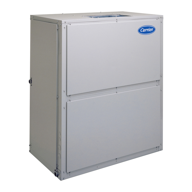
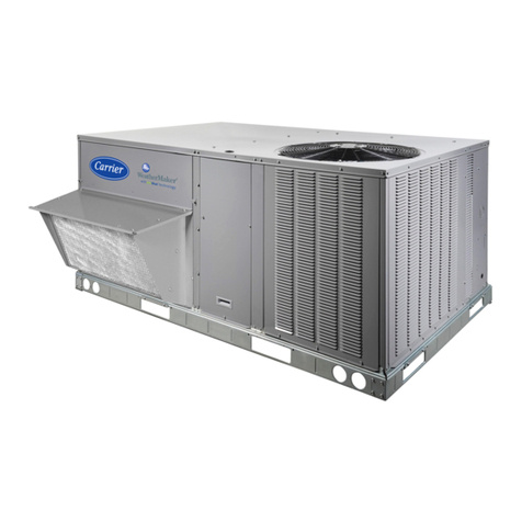
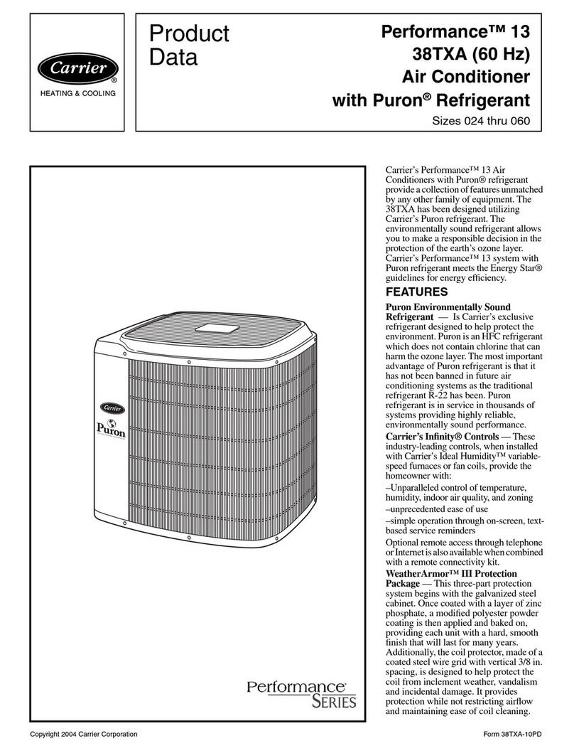
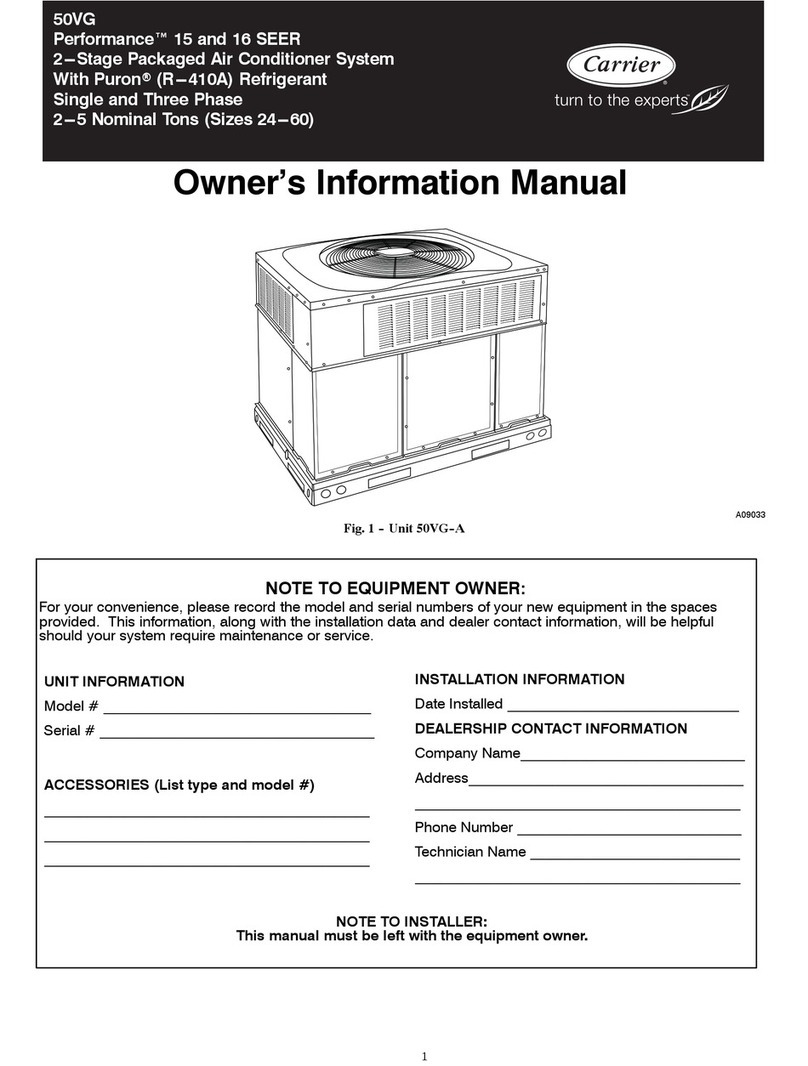
WeatherExpert® 50LC**07-12
Single Package Rooftop
Electric Cooling with Optional Electric Heat
with Puron®(R-410A) Refrigerant

