Unit/CeilingCoordination — Set up a ceiling mock-up
to familiarize all trades with their functions during installa-
tion. Coordinate unit installation with ceiling construction.
This is particularly important in custom installations with
special mounting considerations.
Unit-to-UnitConnections— Use field-fabricated round
duct or flex duct as required.
Unit Suspension
T-BAR SUPPORT — Units are held in place by 2 accessory
T-bar mounting brackets and are locked in place with factory-
supplied wedges.
The mounting brackets fit over the main T-bars, allowing
the T-bars to carry unit weight. Install T-bar support wires
close to each end of T-bar mounting brackets. Make sure
that only wire-hung, main T-bars are used to support unit
weight.
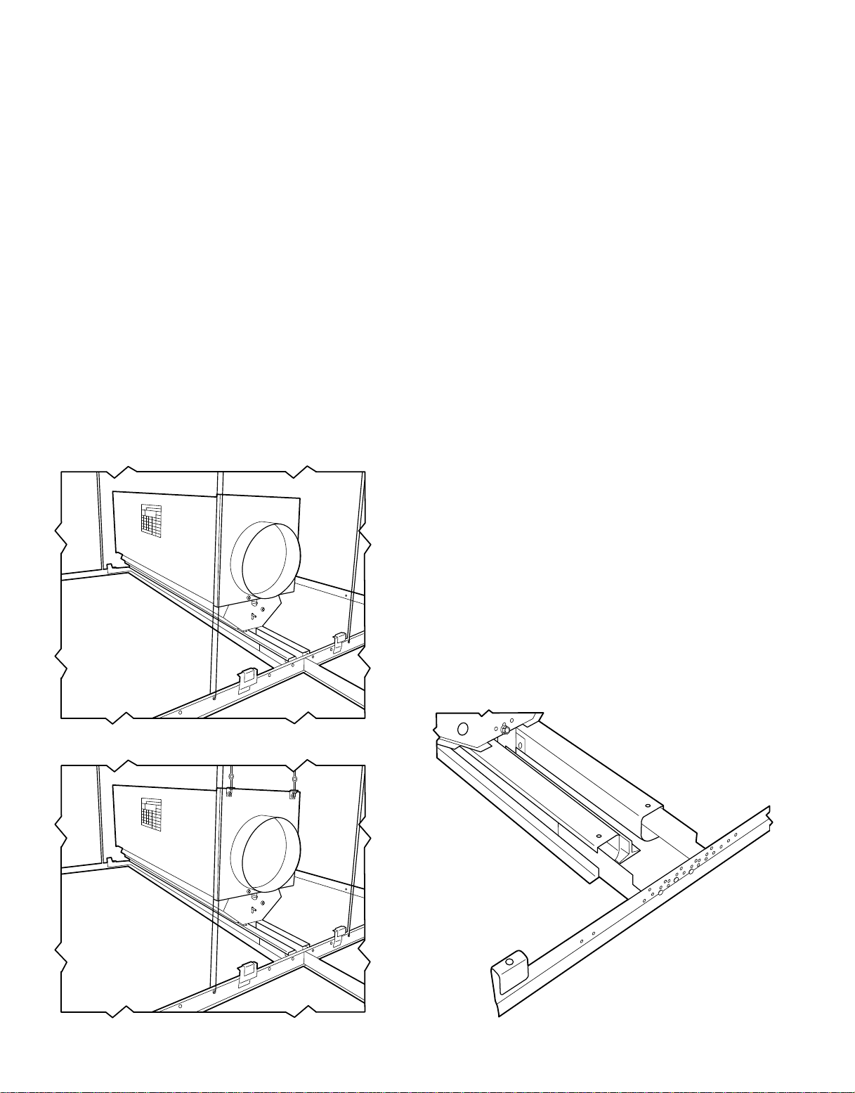
Figure 11 shows a 37HS unit suspended in a T-bar
ceiling.
OTHER SUPPORTS — When installed in nonaccessible ceil-
ings, or in accessible ceilings that require wire-hung units,
the 37HS is held in place by field-installed accessory hanger
mounting brackets. The brackets are wire-hung from the build-
ing structure and are adjustable for proper unit alignment.
Figure 12 shows a 37HS unit wire-hung from the building
structure. NOTE: When units are wire-hung in accessible
ceilings, T-bar mounting brackets can be used for ceiling
alignment.
Unit Installation
T-BAR CEILING
NOTE: Moduline® systems are normally designed with mul-
tiple unit and control arrangements within a single system.
Proper system operation is dependent on careful adher-
ence to the specified job layout. Become familiar with and
check the various control arrangements required on a par-
ticular job before installing the terminals. Additional infor-
mation on unit types and control combinations is given in
Control Arrangements section on page 15.
1. Move units in cartons to installation area.
2. Remove units from cartons and discard packaging ma-
terial. Do not remove protective tape from diffuser. When
handling units, take care not to damage diffusers and
adapters.
3. Arrange units on floor per design layout, diffuser side
up. Check unit identification.
4. Wherever a unit is to be installed directly to another unit,
attach field-supplied connecting duct (flex or metal duct)
to one unit with screws or other mechanical fasteners
before installing the next unit. Seal joint.
5. Install controls in designated units as indicated in job
layout and as described in Control Installation section
on page 22, then proceed to Step 6.
6. Install T-bar mounting bracket in each end of unit as
shown in Fig. 13. Insert bracket in unit side diffusers
and push evenly until bracket seats against diffuser end.
7. Raise unit above ceiling and lower into position. En-
gage T-bar mounting bracket tabs securely over main
T-bars. Do not rest unit diffusers on T-bar flanges. In-
stall 2 locking wedges on each bracket between bracket
and T-bar. See Fig. 14. It may be desirable to crimp the
bracket wedge assembly with pliers to ensure tightness.
8. On single-unit applications, make supply air connection
directly to adapter on end of unit.
9. If other units are to be connected to the first unit, install
T-bar mounting brackets on each end of the adjoining
units.
10. Raise each unit above ceiling and lower into position.
Engage mounting brackets over main T-bar. Reposition
locking wedges at mounting bracket so that they also
secure the mounting bracket of the adjoining unit.
11. Connect interconnecting duct between units, and seal.
Fig. 11 — 37HS Unit Installed in a T-Bar Ceiling
Fig. 12 — 37HS Unit Wire-Hung in a T-Bar Ceiling Fig. 13 — Installing T-Bar Mounting Bracket
8


 null")