Carrier 40MBFAQ User manual

Specifications subject to change without notice.
Fig. 1 — Floor Console 12K
NOTE: Read the entire instruction manual before starting the
installation. Images are for illustration purposes only.
Actual models may differ slightly.
TABLE OF CONTENTS
SAFETY CONSIDERATIONS........................................................2
PARTS LIST ....................................................................................3
ACCESSORIES................................................................................4
SYSTEM REQUIREMENTS...........................................................5
WIRING ...........................................................................................5
DIMENSIONS AND CLEARANCES.............................................6
PRIOR TO INSTALLATION ..........................................................7
ELECTRICAL..................................................................................10
ELECTRICAL DATA......................................................................10
CONNECTION DIAGRAM ............................................................11
WIRING DIAGRAM .......................................................................11
INSTALLATION .............................................................................12
Step 1 - Select Installation Location .................................................12
Step 2 - Installing the Main Body.....................................................12
Step 3 - Take the Indoor Unit Apart to Connect the Pipes ...............14
Step 4 - Drill a Wall Hole for Connective Pipe ................................14
Step 5 - Connect the Drain Hose ......................................................15
TROUBLESHOOTING ...................................................................17
DUCTLESS START-UP CHECKLIST - Single Zone ....................19
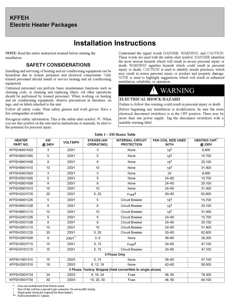
Installation Instructions
40MBFAQ
Floor Console Ductless System
Size 12K

40MBFAQ: Installation Instructions
Manufacturer reserves the right to change, at any time, specifications and designs without notice and without obligations.
2
SAFETY CONSIDERATIONS
Installing, starting up, and servicing air-conditioning equipment
can be hazardous due to system pressures, electrical components,
and equipment location (roofs, elevated structures, etc.).
Only trained, qualified installers and service mechanics should
install, start-up, and service this equipment.
Untrained personnel can perform basic maintenance functions
such as cleaning coils. All other operations should be performed
by trained service personnel.
When working on the equipment, observe precautions in the
literature and on tags, stickers, and labels attached to the
equipment.
Follow all safety codes. Wear safety glasses and work gloves.
Keep quenching cloth and fire extinguisher nearby when brazing.
Use care in handling, rigging, and setting bulky equipment.
Read these instructions thoroughly and follow all warnings or
cautions included in literature and attached to the unit. Consult
local building codes and National Electrical Code (NEC) for
special requirements.
Recognize safety information. This is the safety-alert symbol .
When you see this symbol on the unit and in instruction manuals,
be alert to the potential for personal injury.
When you see this symbol on the unit and in instructions or
manuals, be alert to the potential for personal injury. Understand
these signal words: DANGER, WARNING, and CAUTION.
These words are used with the safety-alert symbol. DANGER
identifies the most serious hazards which will result in severe
personal injury or death. WA R N IN G signifies hazards which
could result in personal injury or death. CAUTION is used to
identify unsafe practices which may result in minor personal
injury or product and property damage. NOTE is used to highlight
suggestions which will result in enhanced installation, reliability,
or operation.
ELECTRICAL SHOCK HAZARD
Failure to follow this warning could result in personal injury or death.
Before installing or servicing unit, always turn off all power to the unit.
There may be more than one disconnect switch. Turn off the accessory
heater power if applicable. Lock out and tag switch with a suitable
warning label.
WA R N I N G
EXPLOSION HAZARD
Failure to follow this warning could
result in death, serious personal injury,
and/or property damage.
Never use air or gases containing oxygen
for leak testing or operating refrigerant
compressors. Pressurized mixtures of air
or gases containing oxygen can lead to
an explosion.
WA R N I N G
EQUIPMENT DAMAGE HAZARD
Failure to follow this caution may result in equipment damage or
improper operation.
Do not bury more than 36 in. (914 mm) of refrigerant pipe in the ground.
If any section of pipe is buried, there must be a 6 in. (152 mm) vertical
rise to the valve connections on the outdoor units. If more than the
recommended length is buried, refrigerant may migrate to the cooler
buried section during extended periods of system shutdown. This causes
refrigerant slugging and could possibly damage the compressor at startup.
CAUTION

40MBFAQ: Installation Instructions
Manufacturer reserves the right to change, at any time, specifications and designs without notice and without obligations.
3
PARTS LIST
Fig. 2 — Parts
Display panel
Drain pipe
Connecting pipe
Air inlet
Air outlet
Air ow louver (at air outlet)
Air inlet (with air lter installed)
1
1
2
3
4
5
6
6
7
1
2
3
4
5
6
7

40MBFAQ: Installation Instructions
Manufacturer reserves the right to change, at any time, specifications and designs without notice and without obligations.
4
ACCESSORIES
Table 1 — Accessories
NOTES:
- If the outdoor unit is higher than the indoor unit, prevent rain from flowing into the indoor unit along the connection pipe by creating a
downward arc in the connection pipe before it enters the wall and enters the indoor unit. Doing so helps ensure rain drips from the
connection pipe before it enters the wall.
- Piping and the interconnecting wiring are field supplied.
Table 2 — Indoor Unit Model Number
ACCESSORY QUANTITY SHAPE
Literature package including owner's manuals, installation instructions and warranty card 3
Wireless remote controller 1
Batteries 2
Heat insulation pipe
1
Copper nut
2
Air freshening filter
2
KBTUH V-PH-HZ ID MODEL NO.
12 208/230-1-60 40MBFAQ12XA3

40MBFAQ: Installation Instructions
Manufacturer reserves the right to change, at any time, specifications and designs without notice and without obligations.
5
SYSTEM REQUIREMENTS
Allow sufficient space for airflow and servicing unit (see Fig. 3 — on page 6 for
the minimum required distances between the unit and walls or ceilings).
Piping
IMPORTANT: Both refrigerant lines must be insulated
separately.
• Minimum refrigerant line length, between the indoor and outdoor units, is 10
ft. (3 m).
• Table 3 lists the pipe sizes for the indoor unit. Refer to the outdoor unit
installation instructions for other allowed piping lengths and refrigerant
information.
Table 3 — Indoor Unit Pipe Sizes
WIRING
All wires must be sized per NEC (National Electrical Code) or CEC (Canadian
Electrical Code) and local codes. Use Electrical Data table MCA (minimum circuit
amps) and MOCP (maximum over current protection) to correctly size the wires
and the disconnect fuse or breakers respectively.
Recommended Connection Method for Power and Communication Wiring:
The main power is supplied to the outdoor unit. The field supplied
14/3 power/communication wiring from the outdoor unit to the indoor unit consists
of four (4) wires and provides the power for the indoor unit. Two wires are high
voltage AC power, one is communication wiring and the other is a ground wire.
To minimize communication interference: If installed in a high
Electromagnetic field (EMF) area and communication issues exist, a 14/2 stranded
shielded wire can be used to replace L2 and (S) between outdoor unit and indoor
unit - landing the shield onto ground in the outdoor unit only.
NOTE: Before performing any electrical work, read these
regulations.
1. All wiring must comply with the local and national electrical codes,
regulations and must be installed by a licensed electrician.
2. All electrical connections must be made according to the Electrical
Connection Diagram located on the panels of the indoor and outdoor
units.
3. If there is a serious safety issue with the power supply, stop work
immediately. Explain your reasoning to the client, and do not install the
unit until the safety issue is properly resolved.
4. Power voltage should be within 90-110% of rated voltage. Insufficient
power supply can cause malfunction, electrical shock, or fire.
5. If connecting power to wiring, a surge protector and main power switch
should be installed.
6. If connecting power to fixed wiring, a switch or circuit breaker that
disconnects all poles and has a contact separation of at least 1/8in
(3mm) must be incorporated in the fixed wiring. The qualified
technician must use an approved circuit breaker or switch.
7. Only connect the unit to an individual branch circuit outlet. Do not
connect another appliance to that outlet.
8. Make sure to properly ground the air conditioner.
9. Every wire must be firmly connected. Loose wiring can cause the
terminal to overheat, resulting in product malfunction and possible fire.
10. Do not allow wires to touch or rest against the refrigerant tubing, the
compressor, or any moving parts within the unit.
11. To avoid getting an electric shock, never touch the electrical
components soon after the power supply has been turned off. After
turning off, the power, always wait 10 minutes or more before touching
the electrical components.
12. Make sure that you do not cross your electrical wiring with your signal
wiring. This may cause distortion and interference.
13. The unit must be connected to the main outlet.
14. No other equipment should be connected to the same power circuit.
15. Connect the outdoor wires before connecting the indoor wires.
NAME 12K
LIQUID PIPE Ø1/4” (6.35)
GAS PIPE Ø1/2” (12.7)
ELECTRICAL DAMAGE HAZARD
Failure to follow this caution may result in equipment damage or
improper operation.
Wires should be sized based on NEC and local codes.
WA R N I N G
EQUIPMENT DAMAGE HAZARD
Failure to follow this caution may result in equipment damage or
improper operation.
Be sure to comply with local codes while running wire from the indoor
unit to the outdoor unit.
Every wire must be connected firmly. Loose wiring may cause the
terminal to overheat or result in unit malfunction. A fire hazard may also
exist. Ensure all wiring is tightly connected.
No wire should touch the refrigerant tubing, compressor or any moving
parts.
Disconnecting means must be provided and shall be located within sight
and readily accessible from the air conditioner.
CAUTION
40MBFAQ: Installation Instructions
Manufacturer reserves the right to change, at any time, specifications and designs without notice and without obligations.
6
DIMENSIONS AND CLEARANCES
Fig. 3 — Dimensions and Clearances
≥39in(1000mm)
7.9in(200mm)
31in(794mm)
≥ 3.9in(100mm)
5.9in(150mm)
24.4in (621mm)
5.9in(150mm)

40MBFAQ: Installation Instructions
Manufacturer reserves the right to change, at any time, specifications and designs without notice and without obligations.
7
PRIOR TO INSTALLATION
REFRIGERANT PIPING CONNECTION
NOTE: When connecting refrigerant piping, do not allow substances
or gases other than the specified refrigerant to enter the unit.
The presence of other gases or substances will lower the
unit’s capacity, and can cause abnormally high pressure in
the refrigeration cycle. This can cause explosion and injury.
NOTE: Ensure that the length of the refrigerant pipe, the number of
bends, and the drop height between the indoor and outdoor
units meets the requirements listed in Table 4.
Table 4 — Maximum Length and Drop Height Based on
Models
Step 1 - Cut Pipes
When preparing refrigerant pipes, take extra care to cut and flare them
properly. This ensures efficient operation and minimizes the need for
future maintenance.
1. Measure the distance between the indoor and outdoor units.
2. Using a pipe cutter, cut the pipe a little longer than the measured
distance.
3. Ensure the pipe is cut at a perfect 90° angle.
Fig. 4 — Pipe Cutter
Step 2 - Remove Burrs
Burrs can affect the air-tight seal of refrigerant piping connection. They
must be completely removed.
1. Hold the pipe at a downward angle to prevent burrs from falling into
the pipe.
2. Using a reamer or deburring tool, remove all burrs from the cut section
of the pipe.
Fig. 5 — Reamer
CAPACITY (BTU/H) PIPING LENGTH MAXIMUM DROP
HEIGHT
12K 15/49 8/26
The branching pipe must be installed horizontally. An angle of more than
10° may cause malfunction.
DO NOT install the connecting pipe until both indoor and outdoor units
have been installed.
Insulate both the gas and liquid piping to prevent water leakage.
CAUTION
Oblique Rough
Warped
90°
DO NOT DEFORM PIPE WHILE CUTTING
Be extra careful not to damage, dent, or deform the pipe while cutting.
This drastically reduces the heating efficiency of the unit.
CAUTION
Pipe
Reamer
Point down

40MBFAQ: Installation Instructions
Manufacturer reserves the right to change, at any time, specifications and designs without notice and without obligations.
8
Step 3 - Flare Pipe Ends
Proper flaring is essential to achieving an airtight seal.
1. After removing burrs from cut pipe, seal the ends with PVC tape to
prevent foreign materials from entering the pipe.
2. Sheath the pipe with insulating material.
3. Place are nuts on both ends of pipe. Ensure they are facing in the right
direction, because you can not put them on or change their direction
after flaring.
Fig. 6 — Flare Pipe Ends
4. Remove PVC tape from the pipe ends when ready to perform flaring
work.
5. Clamp flare form on the end of the pipe. The end of the pipe must
extend beyond the flare form.
Fig. 7 — Clamp Flare Form
6. Place the flaring tool onto the form.
Table 5 — Specifications
7. Turn the flaring tool handle clockwise until the pipe is fully flared.
Flare the pipe in accordance with the dimensions.
Table 6 — Piping Extension Beyond Flare Form
8. Remove the flaring tool and flare form, then inspect the end of the pipe
for cracks and even flaring.
Step 4 - Connect the Pipes
Connect the copper pipes to the indoor unit first, then connect them to the
outdoor unit. Connect the low pressure pipe then the high pressure pipe.
1. When connecting the flare nuts, apply a thin coat of refrigeration oil to
the flared ends of the pipes.
2. Align the center of the two pipes to connect.
Fig. 8 — Align the Pipes
3. Tighten the flare nut as tight as possible by hand.
4. Use an adjustable wrench, grip the nut on the unit tubing.
5. While firmly gripping the nut, use a torque wrench to tighten the flare
nut according to the torque values in Table 6 on page 8.
NOTE: Use an adjustable wrench and a torque wrench when
connecting or disconnecting pipe to or from the unit.
Fig. 9 — Torque fittings
NOTE: Carefully bend the tubing in the middle. DO NOT bend the
tubing more than 90 degrees or more than three times.
6. After connecting the copper pipes to the indoor unit, wrap the power
cable, signal cable and the piping together with binding tape.
NOTE: DO NOT intertwine signal cable with other wires. While
bundling these items together, do not intertwine or cross the
signal cable with any other wiring.
7. Thread this pipeline through the wall and connect it to the outdoor unit.
8. Insulate all the piping, including the valves of the outdoor unit.
9. Open the stop valves of the outdoor unit to start the flow of the
refrigerant between the indoor and outdoor unit.
NOTE: After connecting the piping, wrap the connecting pipe head
with the insulation pipe in the accessory package.
OUTER DIAM.
IN.(MM)
IN. (MM)
MAX. MIN.
Ø1/4” (6.35) 0.05 (1.3) 0.03 (0.7)
Ø3/8” (9.52) 0.06 (1.6) 0.04 (1.0)
Ø1/2” (12.7) 0.07 (1.8) 0.04 (1.0)
Pipe
Gauge
Tightening
Torque
Flare Dimensions
(A) (Unit: In/mm) Flare Shape
1/4”
(6.35)
13.27-14.75 lbsf-ft
(180-200kgf.com)
0.33
/8.4
0.37
/8.7
3/8”
(9.52) 23.6-28.8 lbsf-ft
(320-390kgf.cm)
0.52/
13.2
0.53/
13.5
1/2”
(12.7)
36.14-43.52 lbsf-ft
(490-590kgf.cm)
0.64/
16.2
0.65/
16.5
Flare nut
Copper pipe
Flare form
Pipe
Indoor unit tubing Flare nut Pipe
• Be sure to wrap the insulation around the piping. Direct contact with
the bare piping may result in burns or frostbite.
• Ensure the pipe is properly connected. Over tightening may damage the
bell mouth and under tightening may lead to leakage.
CAUTION
Ensure there is no refrigerant leak after completing the installation work.
If there is a refrigerant leak, ventilate the area immediately and evacuate
the system (refer to the Air Evacuation section of this manual).
CAUTION

40MBFAQ: Installation Instructions
Manufacturer reserves the right to change, at any time, specifications and designs without notice and without obligations.
9
INTERCONNECTING PIPING
Table 7 — Tightening
Fig. 10 — Tighten
Fig. 11 — Flare Nut and Copper Tube
CONDENSATE DRAIN CONNECTION
The unit is supplied with a drain connection to connect the drain piping. When
installing condensate piping, follow these recommendations:
• Condensate piping should slope downward in the direction of the condensate
flow, with a minimum gradient of 1 in. per 100 inches.
• When multiple units are connected to a common condensate drain, ensure the
drain is large enough to accommodate the volume of condensate from all units.
It is also recommended to place an air vent in the condensate piping to prevent
any air locks.
• Condensate piping must not be installed where it may be exposed to freezing
temperatures.
Fig. 12 —Condensate Flow
PIPE DIAMETER INCH (MM) TIGHTENING TORQUE
FT-LB N - M
Ø1/4” (6.35) 10 to 13 13.6 to 17.6
Ø3/8” (9.52) 24 to 31 32.5 to 42.0
Ø1/2” (12.7) 37 to 46 50.1 to 62.3
Ø5/8” (15.88) 50 to 60 67.7 to 81.3
1.5m~2m
Insulating
material
Downward declivity
lower than 1/100
Bend
S shape
VP30
Downward declivity
lower than 1/100
Put as deep as possible
(about 10cm)

40MBFAQ: Installation Instructions
Manufacturer reserves the right to change, at any time, specifications and designs without notice and without obligations.
10
ELECTRICAL
Connections
Remove the sensing device’s installation bearer (see Fig. 13).
Fig. 13 — Remove the sensor bracket
ELECTRICAL DATA
Table 8 — Electrical Data
INDOOR UNITS
INDOOR FAN
MAX FUSE CB AMP
V-PH-HZ FLA (A) HP SYSTEM POWER
FACTOR (%)
12K 208-230/1/60 0.5 1/55 95.6 Refer to outdoor unit installation instructions.
Indoor unit is powered by the outdoor unit.
Sensor Bracket

40MBFAQ: Installation Instructions
Manufacturer reserves the right to change, at any time, specifications and designs without notice and without obligations.
11
CONNECTION DIAGRAM
Fig. 14 — Connection Diagram Size 12
Fig. 15 — Control and Power Wiring
NOTE: For applications where gravity cannot be used for drainage, a condensate pump is required for proper draining.
WIRING DIAGRAM
Fig. 16 — Wiring Diagram Size 12K
1 2 3

40MBFAQ: Installation Instructions
Manufacturer reserves the right to change, at any time, specifications and designs without notice and without obligations.
12
INSTALLATION
NOTE: Panel installation should be performed after piping and
wiring have been completed.
Step 1 - Select Installation Location
Before installing the indoor unit, select an appropriate location.
The following standards are provided to help select an appropriate
location for the unit.
Proper installation locations meet the following standards:
• Enough room exists for installation and maintenance
• Enough room exists for the connection pipe and drainage
• The ceiling is horizontal and its structure can sustain the weight of the indoor
unit.
• The air inlet and outlet are not blocked.
• The airflow can fill the entire room.
• There is no direct radiation from heaters.
DO NOT install the unit in the following locations:
• Areas with oil drilling or fracking
• Coastal areas with high salt content in the air
• Areas with caustic gases in the air, such as hot springs
• Areas that experience power fluctuations, such as factories
• Enclosed spaces, such as cabinets
• Kitchens that use natural gas
• Areas with strong electromagnetic waves
• Areas that store flammable materials or gas
• Rooms with high humidity, such as bathrooms or laundry rooms
NOTE: Recommended distances between the indoor unit. The
distance between the mounted indoor unit should meet the
specifications illustrated (see Fig. 3 — on page 6).
Step 2 - Installing the Main Body
1. After loosening the screws, remove the mounting plate from the unit.
Fig. 17 — Remove the mounting plate
NOTE: If the pipe comes out on the left, it is necessary to loosen the
screws on the bottom mounting plate. If the pipe comes out in
other directions, it is not necessary.
2. Secure the mounting plate, with a tapping screw, onto the wall.
NOTE: It is recommended to secure it to the wall according to the
hanging hole indicated by the arrow on the mounting plate.
The mounting plate must be installed horizontally.
Fig. 18 — Mounting plate
3. Hang the indoor unit on the mounting plate. The unit’s bottom may
touch the floor or remain suspended, however the unit must be installed
vertically.
NOTE: After installation, the unit should remain horizontal without
tilting.
Fig. 19 — Horizontal along wall
Remove the mounting plate
Loosen the screws (Only for left outlet pipe)
Loosen the screw
Mounting plate
Tapping
screw
Washer
˘
0.24in(6mm)

40MBFAQ: Installation Instructions
Manufacturer reserves the right to change, at any time, specifications and designs without notice and without obligations.
13
Bottom Mounting Plate Installation
Installation with a baseboard
If there is a baseboard (see Figure 20) along the intended installation location, the
bottom mounting plate (see Figure 21) needs to be straightened for unit
installation. Use a pair of needle nose pliers (or a sheet metal hand seamer) to
straighten the bottom mounting plate and then secure to the baseboard.
NOTE: The tab is used to secure the lineset when it comes from the left side of
the unit (rear view). If the lineset comes from the right side, the tab is
irrelevant and should be disregarded.
Fig. 20 — Baseboard
Fig. 21 — Straighten
Installation without a baseboard
The bottom mounting plate is secured directly to the wall.
Fig. 22 — Secured to wall
NOTE: To drain smoothly, the position of the drain pipe must
resemble the position in Figure 22 when discharging on the
right hand side.
Baseboard
Straighten
Mounting Plate
Power cordDrain-pipe
Refrigerant pipe

40MBFAQ: Installation Instructions
Manufacturer reserves the right to change, at any time, specifications and designs without notice and without obligations.
14
Step 3 - Take the Indoor Unit Apart to
Connect the Pipes
1. Press and hold the two bottom straps, and then rotate to open the piping
cover plate.
Fig. 23 — Press and hold two straps
2. Remove the pipe cover plate and install the internal and external
connecting pipes.
NOTE: Install the small piping first, and then the large piping.
Step 4 - Drill a Wall Hole for Connective Pipe
1. Determine the location of the wall hole based on the location of the
outdoor unit.
2. Use a 2.5in (65mm) or 3.54in (90mm) hole saw, drill a hole in the wall.
Ensure the hole is drilled at a slight downward angle, so that the
outdoor end of the hole is lower than the indoor end by about 0.5in
(12mm). This ensures proper water drainage.
3. Place the protective wall cuff in the hole. This protects the edges of the
hole and helps seal it when you finish the installation.
Fig. 24 — Drill the Wall Hole
Two straps
EQUIPMENT DAMAGE HAZARD
When drilling the wall hole, make sure to avoid wires and plumbing.
CAUTION
Wall
IndoorOutdoor
≈ 0.5 inch/12mm
19in
(470mm)
6in(150mm)

40MBFAQ: Installation Instructions
Manufacturer reserves the right to change, at any time, specifications and designs without notice and without obligations.
15
Step 5 - Connect the Drain Hose
The drainpipe is used to drain water away from the unit. An improper
installation may cause unit and property damage.
NOTE ON PURCHASING PIPES: Installation requires a
polyethylene tube (exterior diameter = 1-1/2” (3.8cm),
interior diameter = 1-1/4” (3.2cm), which can be obtained
at your local hardware store or dealer.
1. Cover the drainpipe with heat insulation to prevent condensation
and leakage.
2. Attach the mouth of the drain hose to the unit’s outlet pipe. Sheath
the mouth of the hose and clip it firmly with a pipe clasp.
Fig. 25 — Drain Hose Installation
NOTE ON DRAINPIPE INSTALLATION
When using an extended drainpipe, tighten the indoor
connection with an additional protection tube. This prevents
it from pulling loose.
The drainpipe should be pitch down at 1/8” per foot to
prevent water from flowing back into the air conditioner.
Incorrect installation could cause water to flow back into the
unit and flood.
When connecting multiple drainpipes, install the pipes as
shown in Figure 26.
Fig. 26 — Installing Multiple Drainpipes
To ensure smooth drainage, the height difference between the wall outlet and
the hanging plate must be greater than 19in(470mm).
Fig. 27 — Recommended Opening Location
Drainage pipe securing requirements
When installing the drainage pipe (field supplied), secure it with a tie or rope.
Fig. 28 — Secure the Drainage Pipe
Insulate all piping to prevent condensation, which could lead to water
damage.
If the drainpipe is bent or installed incorrectly, water may leak and cause a
water-level switch malfunction.
In the HEAT mode, the outdoor unit discharges water. Ensure that the
drain hose is placed in an appropriate area to avoid
water damage and slippage.
DO NOT pull the drainpipe forcefully; doing so may disconnect it.
CAUTION
Drainpipe
connecting port
Drain hose
Pipe clasp Insulation
Pitch 1/8" per foot
≥4”(
10cm)
19in(470mm)
Recommended opening location
for connecting the pipe outlet
2-1/4”

40MBFAQ: Installation Instructions
Manufacturer reserves the right to change, at any time, specifications and designs without notice and without obligations.
16
WIRELESS REMOTE CONTROL HOLDER
INSTALLATION
Fig. 29 — Wireless Remote RG10L3(2HS)/BGEFU1
1. Use the two screws supplied with the wireless remote control to attach
the mounting bracket to the wall in a location selected by the customer
and within operating range.
2. Install the batteries in the remote control.
3. Place the remote control into the remote control mounting bracket.
NOTE: For remote control operation, refer to the remote control’s
owners manual.
OPTIONAL WIRED WALL-MOUNTED
REMOTE CONTROL INSTALLATION
NOTE: For setup instructions, refer to the Wired Controller
Installation Manual (KSACN0801AAA).
SYSTEM CHECKS
1. Conceal the tubing where possible.
2. Ensure the drain tube slopes downward along its entire length.
3. Ensure all tubing and connections are properly insulated.
4. Fasten tubes to the outside wall, when possible.
5. Seal the hole through which the cables and tubing pass.
INDOOR UNIT
1. Do all remote control buttons function properly?
2. Do the display panel lights work properly?
3. Does the air deflection louver function properly?
4. Does the drain work?
Explain the Following Items To the Customer (with the aid of the
Owner’s Manual):
1. How to turn the air conditioner on and off; selecting COOLING,
HEATING and other operating modes; setting a desired temperature;
setting the timer to automatically start and stop the air conditioner
operation; and all other features of the remote control and display
panel.
2. How to remove and clean the air filter.
3. How to set the air deflection louver.
4. Explain care and maintenance.
5. Present the owner’s manual and installation instructions to customer.
Humidity
Boost

40MBFAQ: Installation Instructions
Manufacturer reserves the right to change, at any time, specifications and designs without notice and without obligations.
17
TROUBLESHOOTING
Common Issues
The issues listed in Table 9 are not malfunctions and in most situations will not require repairs.
Table 9 — Common Issues
NOTE: If problem persists, contact a local dealer or your nearest customer service center. Provide them with a detailed description of
the unit malfunction as well as the model number.
SAFETY PRECUATIONS
If any of the following conditions occurs, turn off your unit immediately:
The power cord is damaged or abnormally warm
You smell a burning odor
The unit emits loud or abnormal sounds
A power fuse blows or the circuit breaker frequently trips
Water or other objects fall into or out of the unit
DO NOT ATTEMPT TO FIX THESE YOURSELF! CONTACT AN
AUTHORIZED SERVICE PROVIDER IMMEDIATELY!
CAUTION
ISSUE POSSIBLE CAUSES
Unit does not turn on when pressing ON/OFF
The unit has a 3-minute protection feature that prevents the unit from overloading.
The unit cannot be restarted within three minutes of being turned off.
Cooling and Heating Models: If the Operation light and PRE-DEF (Pre-heating/Defrost)
indicators are illuminated, or the Operation light is illuminated and the LCD screen displays
“dF”, the outdoor temperature is too cold and the unit’s anti-cold wind is activated to defrost
the unit.
The unit changes from COOL mode to FAN mode
The unit may change its setting to prevent frost from forming on the unit. Once the temperature
increases, the unit starts operating in the previously selected mode again.
The set temperature has been reached, at which point the unit turns off the compressor. The
unit continues operating when the temperature fluctuates again.
The indoor unit emits white mist In humid regions, a large temperature difference between the room’s air and the conditioned
air can cause white mist.
Both the indoor and outdoor units emit white mist When the unit restarts in HEAT mode after defrosting, white mist may be emitted due to
moisture generated from the defrosting process.
The indoor unit makes noises
A squeaking sound is heard when the system is OFF or in COOL mode. The noise is also
heard when the drain pump (optional) is in operation.
A squeaking sound may occur after running the unit in HEAT mode due to expansion and
contraction of the unit’s plastic parts.
Both the indoor unit and outdoor unit make noises
Low hissing sound during operation: This is normal and is caused by refrigerant gas flowing
through both indoor and outdoor units.
Low hissing sound when the system starts, has just stopped running, or is defrosting: This
noise is normal and is caused by the refrigerant gas stopping or changing direction.
Squeaking sound: Normal expansion and contraction of plastic and metal parts caused by
temperature changes during operation can cause squeaking noises.
The outdoor unit makes noises The unit will make different sounds based on its current operating mode.
Dust emits from either the indoor or outdoor unit
The unit may accumulate dust during extended periods of non-use, which will be emitted when
the unit is turned on. This can be mitigated by covering the unit during long periods of
inactivity.
The unit emits a bad odor
The unit may absorb odors from the environment (such as furniture, cooking, cigarettes, etc.)
which will be emitted during operations.
The unit’s filters have become moldy and should be cleaned.
The fan of the outdoor unit does not operate During operation, the fan speed is controlled to optimize product operation.

40MBFAQ: Installation Instructions
Manufacturer reserves the right to change, at any time, specifications and designs without notice and without obligations.
18
NOTE: When troubles occur, check the following points before contacting a repair company.
Table 10 — Troubleshooting
NOTE: FLASH, LIGHT, XEXTINGUISHED
RUNNING LAMP TIMER LAMP DISPLAY MALFUNCTION AND PROTECTION DEFINITION
1 time X E0 Indoor EEPROM malfunction
2 times XE1 Indoor and outdoor unit communication malfunction
4 times X E3 Indoor fan speed malfunction
5 times XE4 Indoor room temperature sensor error
6 times X E5 Evaporator coil temperature sensor leak
7 times XEC Refrigerant leak detection system malfunction
8 times X EE Water level alarm malfunction
11 times XEd Wrong outdoor unit
1 time F0 Overload protection
2 times F1 Outdoor temperature sensor error
3 times F2 Outdoor condenser pipe sensor error
4 times F3 Discharge air temperature sensor error
5 times F4 Outdoor EEPROM error
6 times F5 Outdoor fan speed (DC fan motor only) malfunction
7 times F6 T2b sensor error
8 times F7 Auto-lifting panel communication error
9 times F8 Auto-lifting panel malfunction
10 times F9 Auto-lifting panel is open
1 time P0 Inverter module IPM protection
2 times P1 High/Low voltage protection
3 times P2 Compressor top overheating protection
4 times P3 Outdoor low temperature protection
5 times P4 Compressor drive error
6 times -- Mode conflict
7 times P6 Compressor low-pressure protection
8 times P7 Outdoor IGBT sensor error

40MBFAQ: Installation Instructions
Manufacturer reserves the right to change, at any time, specifications and designs without notice and without obligations.
19
Installation Data
Site Address:_______________________________________________________________________________________________________
City:________________________________________________________ State:___________ Zip Code:__________________
Installing Contractor:______________________________________________________ Contractor Contact #: ( ) _____-___________
Job Name:_______________________________________________________________ Start-up Date:_____________________________
Distributor:_______________________________________________________________
System Details
Are the outdoor unit and indoor unit compatible? YES:______ NO:______
Wiring Electrical
Wire Size and Type Used? AWG:__________ TYPE:_________
Are there any breaks, splices, wire nuts or butt connectors between the outdoor unit and the indoor unit? YES:______ NO:______
Was the wiring from the outdoor unit port to the correct indoor unit verified? YES:______ NO:______
REMARKS:_______________________________________________________________________________________________________
__________________________________________________________________________________________________________________
Voltage Check
Wiring: Single Zone
UNITS MODEL NO. SERIAL NO. CONTROLLER
OUTDOOR UNIT
INDOOR UNIT A
Outdoor Unit
Disconnect
1(L1):GND
Outdoor Unit
Terminal Block
1(L1):GND NOTES:__________________________________
_________________________________________
_________________________________________
_________________________________________
_________________________________________
2(L2):GND 2(L2):GND
1(L1):L2(2) 1(L1):2(L2)
Indoor Unit
Voltage Check
@ Outdoor Unit
1(L1):GND
Indoor Unit
Voltage Check
@ Indoor Unit
1(L1):GND NOTES:__________________________________
_________________________________________
_________________________________________
_________________________________________
_________________________________________
2(L2):GND 2(L2):GND
1(L1):2(L2) 1(L1):2(L2)
2(L2):3(S) 2(L2):3(S)
Outdoor Unit
Disconnect
1(L1):GND
Outdoor Unit
Terminal Block
1(L1):GND NOTES:__________________________________
_________________________________________
_________________________________________
_________________________________________
_________________________________________
2(L2):GND 2(L2):GND
1(L1):L2(2) 1(L1):2(L2)
Indoor Unit
Voltage Check
@ Outdoor Unit
1(L1):GND
Indoor Unit
Voltage Check
@ Indoor Unit
1(L1):GND NOTES:__________________________________
_________________________________________
_________________________________________
_________________________________________
_________________________________________
2(L2):GND 2(L2):GND
1(L1):2(L2) 1(L1):2(L2)
2(L2):3(S) 2(L2):3(S)
DUCTLESS START-UP CHECKLIST - Single Zone

© 2023 Carrier. All rights reserved.
Edition Date: 01/23 Catalog No: IM-40MBFAQ-01
Replaces: NEW
40MBFAQ: Installation Instructions
Manufacturer reserves the right to change, at any time, specifications and designs without notice and without obligations.
20
Ductless Start-Up Checklist (CONT)
Piping
Leak Check:
System held 500 psig (max. 550psi) for a minimum of 30 minutes using dry nitrogen. YES:______ NO:______
Evacuation Method:
•Was the Triple Evacuation Method used as outlined in the installation manual? YES:______ NO:______
• Was the Deep Vacuum Method used as outlined in the installation manual? YES:______ NO:_______
• Did the System Hold 500 microns for 1 hour? YES:______ NO:_______
• Does the line set match the diameter of the evaporator connections? YES:______ NO:_______
• For Conventional Fan Coils, does the line set match the outdoor unit size? YES:______ NO:_______
Single Zone Piping:
Has the liquid pipe length been measured and the additional charge calculated? Size:___________ Length:_________ Charge:____________
Performance Check
NOTE:
• T1 - Ambient Space Temperature Sensor
• T2 - IDU Coil Temperature Sensor
• T3 - Outdoor Coil Temperature Sensor
• T4 - Outdoor Ambient Temperature
• Tb - Suction Line Temperature @PMV
• Tp - Discharge Temperature Sensor
• Th - IPM Board Temperature
• LA/Lr - PMV Position
Error Codes
Were there any error codes present at start-up? YES:______ NO:______
Comments:
__________________________________________________________________________________________________________________
__________________________________________________________________________________________________________________
__________________________________________________________________________________________________________________
NOTES:
PORT LIQUID SIZE SUCTION SIZE LENGTH CHARGE NOTES:____________________________________
___________________________________________
___________________________________________
A
For 1:1 Single Zone Systems: Adjust the set-point to create an operational call for the desired testing operation. Allow the system to run for a
minimum of 10 min. and record the following details:
(Operational data recorded on applicable heads with the wireless remote controller’s Point Check function)
UNIT
SET-POINT
MODE T1 T2 T3 T4 Tb Tp Th LA/Lr
A
Indoor Unit Error Code: Notes:
Outdoor Unit Error Code:
Wall Controller:
24V Interface:
Other manuals for 40MBFAQ
1
Table of contents
Other Carrier Heater manuals

Carrier
Carrier KFFEH Series User manual

Carrier
Carrier CPCRKHTR002A00 User manual

Carrier
Carrier 48HJ015-025 Guide

Carrier
Carrier 42N S Series User manual

Carrier
Carrier 46SE Quick setup guide

Carrier
Carrier 42AM ATEX Manual

Carrier
Carrier EHC05CKN User manual

Carrier
Carrier KAACH1401 User manual

Carrier
Carrier 50DJ034 User manual

Carrier
Carrier 46S User manual
Popular Heater manuals by other brands

NFL
NFL Helmet owner's manual

Flagro
Flagro FV-200RC Series Operating instructions manual

Unold
Unold TOWER ELECTRONIC Instructions for use

Carlo Loysch
Carlo Loysch Thermodom EFB Series Installation and operating instructions

Goldair
Goldair GCT330 operating instructions

Dru
Dru ART 2-01 Instructions for installation and operation