Carrier CRHEATER101A00 User manual

Manufacturer reserves the right to discontinue, or change at any time, specifications or designs without notice and without incurring obligations.
Catalog No. 04-53500315-01 Printed in U.S.A. Form IIK-CRHEATER-07 Pg 1 9-21 Replaces: IIK-CRHEATER-04
Installation Instructions
P/N CRHEATER101A00-CRHEATER112A00, CRHEATER103B00,
CRHEATER104B00, CRHEATER113B00-CRHEATER116B00,
CRHEATER117A00-CRHEATER119A00, CRHEATER128B00,CRHEATER129B00,
CRHEATER264A00-CRHEATER269A00, CRHEATER288A00-CRHEATER297A00,
CRHEATER299A00, CRHEATER301A00, CRHEATER308A00,
CRHEATER316A00-CRHEATER321A00, CRHEATER360A00-CRHEATER364A00,
CRHEATER367A00-CRHEATER384A00,
CRSINGLE037A00-CRSINGLE054A00(STD SCCR),
CRSINGLE064A00-CRSINGLE073A00(High SCCR)
NOTE: Read these instructions completely before attempting to
install this accessory.
NOTE: HSCCR is defined as “High Short Circuit Current
Rating”. Our standard SCCR for units is 5kA, whereas HSCCR
(for Carrier units) can be 10kA to 65kA, therefor it is called
“High” SCCR or HSCCR.
CONTENTS
Page
SAFETY CONSIDERATIONS . . . . . . . . . . . . . . . . . . . 1
PACKAGE CONTENTS . . . . . . . . . . . . . . . . . . . . . . . . 3
GENERAL . . . . . . . . . . . . . . . . . . . . . . . . . . . . . . . . . . . 6
Puron®Units . . . . . . . . . . . . . . . . . . . . . . . . . . . . . . . . 6
Single Point Boxes and Fuses
(STD SCCR Units) . . . . . . . . . . . . . . . . . . . . . . . . . . 6
• NON-HIGH SCCR FIOP
• NO FUSES (NON-HIGH SCCR VERSION ONLY)
• UNITS WITH FACTORY-INSTALLED HACR
(NON-HIGH SCCR VERSION ONLY)
• HIGH SCCR OPTION
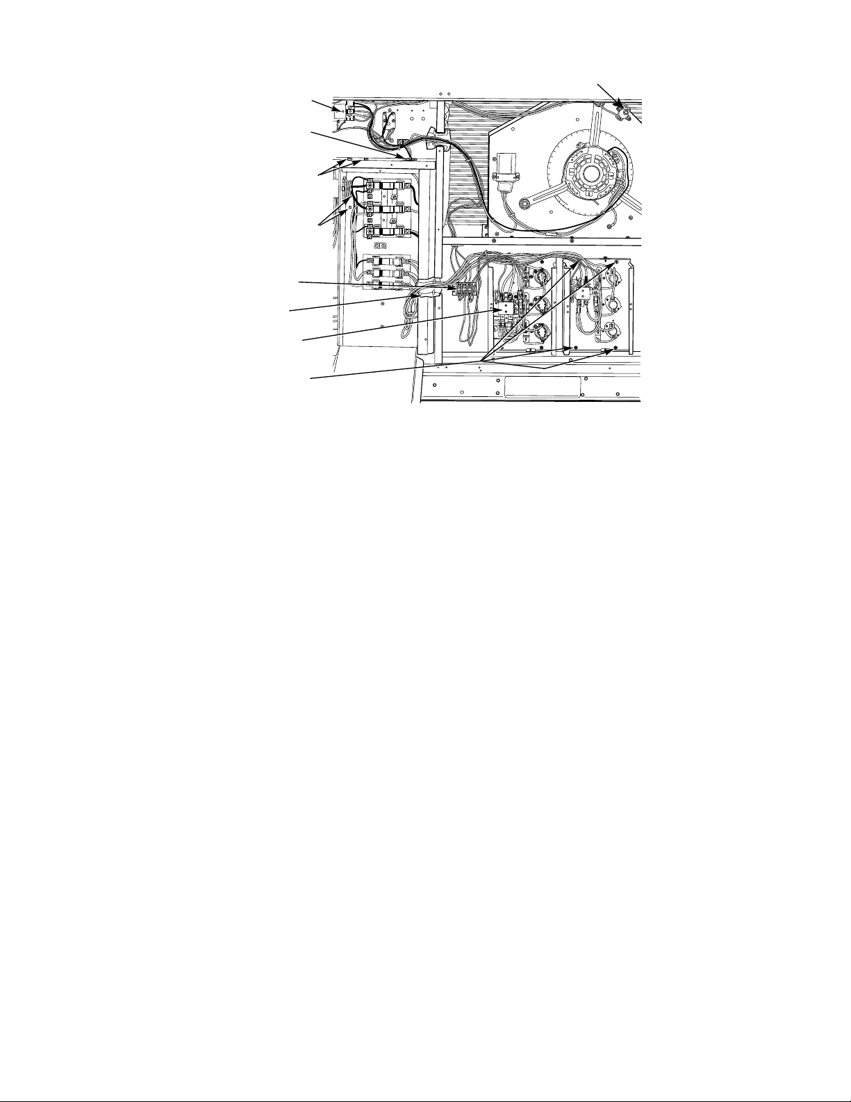
Electric Heaters . . . . . . . . . . . . . . . . . . . . . . . . . . . . . . 7
• SINGLE POINT BOX CONTENTS
Control Wiring . . . . . . . . . . . . . . . . . . . . . . . . . . . . . . . 8
• TERMINAL BLOCK TB10 (208/230-V UNITS)
(STD SCCR VERSION ONLY)
GENERAL INSTALLATION SEQUENCE . . . . . . . . . 10
UNIT-SPECIFIC INSTALLATION INSTRUCTIONS . . 11
SMALL TO MEDIUM CABINET INSTALLATION . . . 11
Check Sales Packages . . . . . . . . . . . . . . . . . . . . . . . 11
Disconnect Field Power Supply . . . . . . . . . . . . . . . . 11
• INSTALLING ELECTRIC HEATER (STD SCCR AND
HIGH SCCR UNITS)
LARGE CABINET INSTALLATION . . . . . . . . . . . . . . 21
Check Sales Packages . . . . . . . . . . . . . . . . . . . . . . . 21
Disconnect Field Power Supply . . . . . . . . . . . . . . . . 21
Install Single Point Box
(CRSINGLE047A00, 049A00, 050A00-054A00 [STD
SCCR], CRSINGLE064-073A00 [High SCCR]) . . 21
Install CRHEATER288A00-296A00,
367A00-370A00, 374A00-377A00,
381A00-384A00 (STD SCCR and High SCCR) . . .24
UNIT POWER SUPPLY WIRING –ALL UNITS . . . . .31
New Unit Without Factory Disconnect or HACR . . .31
• INSTALLATION WITHOUT SINGLE POINT BOX
• INSTALLATION WITH SINGLE POINT BOX
New Unit With Factory Disconnect . . . . . . . . . . . . .32
• IF REQUIRED MINIMUM DISCONNECT VALUE IS
LOWER THAN RATING IN TABLE 14
• IF REQUIRED MINIMUM DISCONNECT VALUE IS
HIGHER THAN RATING IN TABLE 14
• FOR UNIT WITH 115-A DISCONNECT AND
REQUIRED MINIMUM DISCONNECT VALUE PER
UNIT INFO DATA PLATE IS LESS THAN 200-A
• FOR UNIT WITH 115-A DISCONNECT AND
REQUIRED MINIMUM DISCONNECT VALUE PER
UNIT INFODATA PLATE IS GREATER THAN 200-A
New Unit With Factory HACR . . . . . . . . . . . . . . . . . .32
• IF MARKED HACR VALUE ON UNIT DATAPLATE IS
UNCHANGED FROM RATING UNIT-MOUNTED
HACR
• IF MARKED HACR VALUE ON UNIT DATAPLATE IS
GREATER THAN RATING ON UNIT-MOUNTED
HACR
Existing Unit . . . . . . . . . . . . . . . . . . . . . . . . . . . . . . . .32
Complete Unit Installation . . . . . . . . . . . . . . . . . . . . .33
APPENDIX A —AC-1, AC-2 COOLING
APPLICATIONS. . . . . . . . . . . . . . . . . . . . . . . . . . . .34
APPENDIX B —AC-3 50LC COOLING
APPLICATIONS. . . . . . . . . . . . . . . . . . . . . . . . . . . .52
APPENDIX C —HP-1, HP-2 HEAT PUMP
APPLICATIONS. . . . . . . . . . . . . . . . . . . . . . . . . . . .61
APPENDIX D —ELECTRIC HEATER DATA . . . . . . .76
SAFETY CONSIDERATIONS
Installation of this accessory can be hazardous due to system
pressures, electrical components, and equipment location (such as
a roof or elevated structure). Only trained, qualified installers and
Accessory Electric Heater and Single Point Box
for Small Rooftop Units
with Electric Cooling and Heat Pump
Select 3 to 15 Ton Units

2
service technicians should install, start-up, and service this
equipment.
When installing this accessory, observe precautions in the
literature, labels attached to the equipment, and any other safety
precautions that apply:
• Follow all safety codes
• Wear safety glasses and work gloves
• Use care in handling and installing this accessory
It is important to recognize safety information. This is the safety-
alert symbol: . When you see this symbol on the unit and in
instructions or manuals, be alert to the potential for personal
injury.
Understand the signal words DANGER, WARNING, CAUTION,
and NOTE. These words are used with the safety-alert symbol.
DANGER identifies the most serious hazards which will result in
severe personal injury or death. WARNING signifies hazards
which could result in personal injury or death. CAUTION is used
to identify unsafe practices, which may result in minor personal
injury or product and property damage. NOTE is used to highlight
suggestions which will result in enhanced installation, reliability,
or operation.
NOTE: The above is an encompassing list of all models that will include
the HSCCR option. Contact your local representative on current
offerings.
WARNING
Failure to follow this caution could result in personal injury or
death.
Turn off all power to unit and install lockout tag. Power can
come to unit from multiple sources. Verify power is off with a
meter or probe.
CAUTION
PERSONAL INJURY HAZARD
Failure to follow this caution may result in personal injury.
Sheet metal parts may have sharp edges or burrs. Use care and
wear appropriate protective clothing, safety glasses and gloves
when handling parts and servicing air conditioning equipment.
Table 1 — Package Usage
CARRIER MODELS
MODEL NUMBER CHASSIS GROUP UNIT SIZES
STD SCCR HSCCR
50HC AC-2 04-14 07-14
50HCQ HP-2 04-12 07-12
50KC AC-1 04-06 N/A
50KCQ HP-1 04-06 N/A
50LC AC-3 04-12 07-12
50TC AC-1 04-16 08-16
50TCQ HP-1 04-14 08-14
BRYANT MODELS
MODEL NUMBER CHASSIS GROUP UNIT SIZES
STD SCCR HSCCR
547J HP-1 04-06 N/A
548J HP-1 04-14 07-14
549J HP-2 04-12 07-12
551J AC-2 04-14 07-14
558J AC-1 04-16 07-14
559J AC-1 04-06 N/A
ICP MODELS
MODEL NUMBER CHASSIS GROUP UNIT SIZES
STD SCCR HSCCR
RAH AC-2 036-150 072-150
RAS AC-1 036-180 072-150
RAX AC-1 036-060 N/A
RHH HP-1 036-150 072-120
RHS HP-2 036-120 072-150
RHX HP-1 036-060 N/A
LEGEND
AC — Cooling Only (air conditioner)
HP — Heat Pump
1— Standard Efficiency
2— High Efficiency
3— Ultra High Efficiency

3
PACKAGE CONTENTS
*Not included with CRHEATER101A00-109A00, 297A00, 301A00,
360A00-362A00, 371A00-373A00, 378A00, 379A00.
†Supplied with electric heater packages CRHEATER101A00, 102A00,
103B00, 104B00, 360A00-362A00 only.
**Supplied with package CRHEATER301A00, 128B00, 129B00,
360A00-364A00, 371A00-373A00, 378A00-380A00 only.
*Supplied with package CRHEATER367A00-370A00, 374A00-377A00,
381A00-384A00 only.
Table 2 — Electric Heaters
CRHEATER101A00-112A00,103B00,
104B00,113B00-116B00,117A00-119A00,
128B00,129B00,264A00-269A00,297A00,
301A00,308A00, 316A00-321A00, 360A00-364A00,
371A00-373A00, 378A00-380A00
(STD SCCR and High SCCR)
QUANTITY CONTENTS
1Heater Module
1Heater Slider Track*
4Screws*
1Wiring Label
1Red Wire (10 Gage)†
1Splice Connector†
1Wire Tie†
1Label, Max Temp/Static
1Heater Cover**
Table 3 — Electric Heaters
CRHEATER288A00-296A00, 299A00, 367A00-370A00,
374A00-377A00, 381A00-384A00
(STD SCCR and High SCCR)
QUANTITY CONTENTS
1Heater Module
1Heater Slide Track
4Screws
1Wiring Label
1Label, Max Temp/Static
1Heater Cover*
Table 4 — Single Point Box Kits (STD SCCR)
CRSINGLE037A00
QUANTITY CONTENTS
1Single Point Box Housing Assembly
(Height 18 in./449 mm)
1Terminal Block
3Conductors, Tap, #10
1Rain Shield With Conduit Seal
12 Screws, #10 x 1/2 in.
7Wire Ties
1Tube Clamp
1Seal Strip
CRSINGLE038A00
QUANTITY CONTENTS
1Single Point Box Housing Assembly
(Height 18 in./449 mm)
1Terminal Block/Fuse Holder
1Fuse Block
6Fuses, 60-A Class RK5
1Power Distribution Harness
3Conductors, Tap, #10
1Rain Shield With Conduit Seal
12 Screws, #10 x 1/2 in.
7Wire Ties
1Tube Clamp
1Seal Strip
Table 4 — Single Point Box Kits (cont)
CRSINGLE039A00
QUANTITY CONTENTS
1Single Point Box Housing Assembly
(Height 18 in./449 mm)
1Terminal Block/Fuse Holder
2Fuse Block
9Fuses, 60-A Class RK5
1Power Distribution Harness
3Conductors, Tap, #10
1Rain Shield With Conduit Seal
12 Screws, #10 x 1/2 in.
7Wire Ties
1Tube Clamp
1Seal Strip
CRSINGLE040A00
QUANTITY CONTENTS
1Single Point Box Housing Assembly
(Height 18 in./449 mm)
1Terminal Block/fuse Holder
1Fuse Block
4Fuses, 60-A Class RK5
1Power Distribution Harness
2Conductors, Tap, #10
1Rain Shield With Conduit Seal
12 Screws, #10 x 1/2 in.
7Wire Ties
1Tube Clamp
1Seal Strip
CRSINGLE041A00
QUANTITY CONTENTS
1Single Point Box Housing Assembly
(Height 18 in./449 mm)
1Terminal Block/Fuse Holder
1Fuse Block
6Fuses, 60-A Class RK5
1Power Distribution Harness
2Conductors, Tap, #10
1Rain Shield With Conduit Seal
12 Screws, #10 x 1/2 in.
7Wire Ties
1Tube Clamp
1Seal Strip
CRSINGLE042A00
QUANTITY CONTENTS
1Single Point Box Housing Assembly
(Height 25 in./639 mm)
1Terminal Block
3Conductors, Tap, #10
1Rain Shield With Conduit Seal
8Screws, #10 x 1/2 in.
7Wire Ties
1Seal Strip

4
Table 4 — Single Point Box Kits (cont)
CRSINGLE043A00
QUANTITY CONTENTS
1Single Point Box Housing Assembly
(Height 25 in./639 mm)
1Terminal Block/Fuse Holder
1Fuse Block
2Terminal Block (TB-10)
6Fuses, 60-A Class RK5
1Power Distribution Harness
6Conductors, Tap, #10
2Screws, #8 x 1/2 in.
1Rain Shield With Conduit Seal
8Screws, #10 x 1/2 In.
7Wire Ties
1Seal Strip
CRSINGLE044A00
QUANTITY CONTENTS
1Single Point Box Housing Assembly
(Height 25 in./639 mm)
1Terminal Block
2Fuse Block
6Fuses, 60-A Class T (600v)
1Power Distribution Harness
3Conductors, Tap, #10
1Rain Shield With Conduit Seal
8Screws, #10 x 1/2 in.
7Wire Ties
1Seal Strip
CRSINGLE045A00
QUANTITY CONTENTS
1Single Point Box Housing Assembly
(Height 25 in./639 mm)
1Terminal Block/Fuse Holder
2Fuse Block
9Fuses, 60-A Class RK5
1Power Distribution Harness
6Conductors, Tap, #10
2Terminal Block (TB-10)
2Screws, #8 x 1/2 in.
1Rain Shield With Conduit Seal
8Screws, #10 x 1/2 in.
7Wire Ties
1Seal Strip
CRSINGLE046A00
QUANTITY CONTENTS
1Single Point Box Housing Assembly
(Height 25 in./639 mm)
1Terminal Block/Fuse Holder
3Fuse Block
12 Fuses, 60-A Class RK5
1Power Distribution Harness
3Conductors, Tap, #10
1Rain Shield With Conduit Seal
8Screws, #10 x 1/2 In.
7Wire Ties
1Seal Strip
Table 4 — Single Point Box Kits (cont)
CRSINGLE047A00
QUANTITY CONTENTS
1Single Point Box Housing Assembly
(Height 33 in./845 mm)
1Terminal Block
3Conductors, Tap, #10
1Rain Shield, Small
1Rain Shield With Conduit Seal
8Screws, #10 x 1/2 in.
7Wire Ties
1Seal Strip
CRSINGLE048A00
QUANTITY CONTENTS
1Single Point Box Housing Assembly
(Height 25 in./639 mm)
1Terminal Block
3Fuse Block
9Fuses, 60-A Class RK5
1Power Distribution Harness
3Conductors, Tap, #10
1Rain Shield With Conduit Seal
8Screws, #10 x 1/2 in.
7Wire Ties
1Seal Strip
CRSINGLE049A00
QUANTITY CONTENTS
1Single Point Box Housing Assembly
(Height 33 in./845 mm)
1Terminal Block/Fuse Holder
1Fuse Block
6Fuses, 60-A Class RK5
1Power Distribution Harness
8Conductors, Tap, #10
2Terminal Block (TB-10)
2Screws, #8 x 1/2 in.
1Rain Shield, Small
1Rain Shield With Conduit Seal
8Screws, #10 x 1/2 in.
7Wire Ties
1Seal Strip
CRSINGLE050A00
Quantity CONTENTS
1Single Point Box Housing Assembly
(Height 33 in./845 mm)
1Terminal Block
2Fuse Block
6Fuses, 60-A Class T (600v)
1Power Distribution Harness
3Conductors, Tap, #10
1Rain Shield, Small
1Rain Shield With Conduit Seal
8Screws, #10 x 1/2 in.
7Wire Ties
1Seal Strip

5
Table 5 — Single Point Box Kits (High SCCR)
Table 4 — Single Point Box Kits (cont)
CRSINGLE051A00
QUANTITY CONTENTS
1Single Point Box Housing Assembly
(Height 33 in./845 mm)
1Terminal Block/fuse Holder
2Fuse Block
9Fuses, 60-A Class RK5
1Power Distribution Harness
8Conductors, Tap, #10
2Terminal Block (TB-10)
2Screws, #8 x 1/2 in.
1Rain Shield, Small
1Rain Shield With Conduit Seal
8Screws, #10 x 1/2 in.
7Wire Ties
1Seal Strip
CRSINGLE052A00
QUANTITY CONTENTS
1Single Point Box Housing Assembly
(Height 33 in./845 mm)
1Terminal Block
3Fuse Block
9Fuses, 60-A Class T (600 v)
1Power Distribution Harness
3Conductors, Tap, #10
1Rain Shield, Small
1Rain Shield With Conduit Seal
8Screws, #10 x 1/2 in.
7Wire Ties
1Seal Strip
CRSINGLE053A00
QUANTITY CONTENTS
1Single Point Box Housing Assembly
(Height 33 in./845 mm)
1Terminal Block
4Fuse Block
12 Fuses, 60-A Class RK5
1Power Distribution Harness
8Conductors, Tap, #10
2Terminal Block (TB-10)
2Screws, #8 x 1/2 in.
1Rain Shield, Small
1Rain Shield With Conduit Seal
8Screws, #10 x 1/2 in.
7Wire Ties
1Seal Strip
Table 4 — Single Point Box Kits (cont)
CRSINGLE054A00
QUANTITY CONTENTS
1Single Point Box Housing Assembly
(Height 33 in./845 mm)
1Terminal Block
5Fuse Block
15 Fuses, 60-A Class RK5
1Power Distribution Harness
8Conductors, Tap, #10
2Terminal Block (TB-10)
2Screws, #8 x 1/2 in.
1Rain Shield, Small
1Rain Shield With Conduit Seal
8Screws, #10 x 1/2 in.
7Wire Ties
1Seal Strip
CRSINGLE064A00
QUANTITY CONTENTS
1Single Point Box Housing Assembly 25 in. (639 mm)
1Terminal Block
1Fuse Block
3Fuse Class J (JKS)
1Unit Power Wire Harness- 4 GA, 3 wire
1Rain Shield
7Screws
5Wire Ties
1Seal Strip
CRSINGLE065A00
QUANTITY CONTENTS
1Single Point Box Housing Assembly 25 in. (639 mm)
1Terminal Block
2Fuse Block
6Fuse Class J (JKS)
1Unit Power Wire Harness- 4 GA, 3 wire
1Rain Shield
7Screws
5Wire Ties
1Seal Strip
CRSINGLE066A00
QUANTITY CONTENTS
1Single Point Box Housing Assembly 25 in. (639 mm)
1Terminal Block
3Fuse Block
9Fuse Class J (JKS)
1Unit Power Wire Harness- 4 GA, 3 wire
1Rain Shield
7Screws
5Wire Ties
1Seal Strip

6
Table 5 — Single Point Box (High SCCR) (cont) Table 5 — Single Point Box (High SCCR) (cont)
GENERAL
Puron®Units
This installation instruction manual describes the installation of
electric heaters and associated fuse block/field power termination
kits (single point box or SPB) on select small rooftop units in
nominal cooling capacities from 3 to 15 tons. These rooftop units
use Puron refrigerant (R-410A). See Package Usage tables on
page 2 for applicable unit models. Unit types include cooling units
(AC) and heat pumps (HP) distributed over several chassis sizes.
Unit types AC-1, AC-2, HP-1, HP-2 are identified. Unit type
AC-3 consists of a single model: Carrier 50LC.
This information does not include selection data. Refer to project
plans, job submittals and selection programs for heater and field
power termination/SPB kit usage.
Some electric heaters used on these Puron (R-410A) units may
also be installed in earlier R-22 rooftop units. For details on use
with R-22 units, contact your local distributor office.
Single Point Boxes and Fuses
(STD SCCR Units)
The single point box (SPB) kits provide a field power termination
location plus an enclosure for heater fuses when required by code.
The SPBs are installed under the unit’s main control box and
include a cover plus all internal wiring (see Fig. 1). Minimum
components of the non-High SCCR (High Short-Circuit Current
Rating) option SPB are a field power terminal block with tap
conductors (to connect to the unit’s main control box field
terminals). Minimum components of the High SCCR option SPB
are a field power terminal block with tap conductors (to convert to
the unit’s main control box field terminals) and at least one fuse
block with fuses. Maximum component population for both
non-High SCCR and High SCCR options. includes up to five fuse
blocks. See Table 4.
NON-HIGH SCCR FIOP
Fuses for electric heater circuits are required and provided when
the unit’s MOCP exceeds 60-A or when the total heater Full Load
Amp value exceeds 48-A. When fuses are required and provided,
the cooling circuit is also provided with fuse protection; some
units require minor wiring changes in the main control box (see
section on TB10 terminal blocks).
CRSINGLE067A00
QUANTITY CONTENTS
1Single Point Box Housing Assembly 33 in (845 mm)
1Terminal Block
1Fuse Block
3Fuse Class J (JKS)
1Unit Power Wire Harness- 4 GA, 3 wire
1Rain Shield
7Screws
6Wire Ties
1Seal Strips
CRSINGLE068A00
QUANTITY CONTENTS
1Single Point Box Housing Assembly 33 in (845 mm)
1Terminal Block
2Fuse Block
6Fuse Class J (JKS)
1Unit Power Wire Harness- 4 GA, 3 wire
1Rain Shield
7Screws
6Wire Ties
1Seal Strips
CRSINGLE069A00
QUANTITY CONTENTS
1Single Point Box Housing Assembly 33 in (845 mm)
1Terminal Block
3Fuse Block
9Fuse Class J (JKS)
1Unit Power Wire Harness- 4 GA, 3 wire
1Rain Shield
7Screws
6Wire Ties
1Seal Strips
CRSINGLE070A00
QUANTITY CONTENTS
1Single Point Box Housing Assembly 33 in (845 mm)
1Terminal Block
4Fuse Block
12 Fuse Class J (JKS)
1Unit Power Wire Harness- 4 GA, 3 wire
1Rain Shield
7Screws
6Wire Ties
1Seal Strips
CRSINGLE071A00
QUANTITY CONTENTS
1Single Point Box Housing Assembly 33 in (845 mm)
1Terminal Block
2Fuse Block
6Fuse Class J (JKS)
1Unit Power Wire Harness- 2 GA, 3 wire
1Rain Shield
7Screws
6Wire Ties
1Seal Strips
CRSINGLE072A00
QUANTITY CONTENTS
1Single Point Box Housing Assembly 33 in (845 mm)
1Terminal Block
3Fuse Block
9Fuse Class J (JKS)
1Unit Power Wire Harness- 2 GA, 3 wire
1Rain Shield
7Screws
6Wire Ties
1Seal Strips
CRSINGLE073A00
QUANTITY CONTENTS
1Single Point Box Housing Assembly 33 in (845 mm)
1Terminal Block
4Fuse Block
12 Fuse Class J (JKS)
1Unit Power Wire Harness- 2 GA, 3 wire
1Rain Shield
7Screws
6Wire Ties
1Seal Strips

7
Fig. 1 — Typical Single Point Kit Installation
NO FUSES (NON-HIGH SCCR VERSION ONLY)
If the unit’s MOCP device rating is 60-A or less, then the MOCP
device is recognized as providing the required overcurrent
protection to the heater and no internal fusing is required. If two
heater modules are installed, a single point box that contains only
a field power terminal block is required. See tables at the
beginning of Appendix A, B and C for where-used information on
the single point boxes and for the relevant connections wiring
diagram.
For High SCCR option, see Tables A-C (Single Point BoxWiring
Diagrams) of Appendix D on page 76 for information on the
single point boxes and see Fig. AY-BB for the relevant connection
wiring diagram.
UNITS WITH FACTORY-INSTALLED HACR
(NON-HIGH SCCR VERSION ONLY)
NOTE: HACR is not available on the High SCCR option.
The amp rating of the HACR factory-installed option is based on
the size, voltage, indoor motor and other electrical options of the
unit as shipped from the factory. When field-installed accessory
electric heaters are added or changed in the unit, the HACR may
no longer be of the proper amp rating and therefore will need to be
removed from the unit. See unit nameplate and label on factory
installed HACR for the amp rating of the HACR that was shipped
with the unit from the factory. See unit nameplates for the proper
fuse, HACR or maximum over-current protection device required
on the unit with field installed electric heat.
HIGH SCCR OPTION
Unlike the non-High SCCR version, fuses for electric heater cir-
cuits are required regardless of the unit’s MOCP to provide the
unit rated High SCCR rating for the electric heaters.
Additionally, unlike the non-High SCCR version, TB10’s are not
required for the High SCCR option.
Units with High SCCR ratings must use a single point box
(specifically for High SCCR application) for all electric heat
installations. These boxes contain High SCCR fusing rated to
protect the heaters. General installation of the Single Point Box
(SPB) and Electric Heaters is the same fro both STD SCCR and
High SCCR units. Unit power wiring must enter through the
SPB and then power is routed to the Unit Control Fuse Box
using wire harness provided. See High SCCR Single Point Box
installation details in this document.
Electric Heaters
Heaters are shipped with one heater per carton. The carton is
marked with a Sales Package Number. On all heaters except
CRHEATER101A00 through 119A00, 103B00, 104B00, 113B00
through 116B00, 128B00, and 129B00, the heater Model Number
(as marked on the heater infoplate) is the same as the Sales
Package number. On CRHEATER101A00 through 119A00,
103B00, 104B00, 113B00 through 116B00, 128B00, and 129B00,
the value in position 9 of the part number differs between the sales
package part number (value is 1 and bare heater model number
(value is 0).
The heaters are modular in design, with heater frames holding
open coil resistance wires strung through ceramic insulators, limit
switches and one or two control contactors. Power conductors are
attached. One or two heater modules may be used in a unit.
Heater modules are installed in the compartment below the indoor
(supply) fan outlet. Access is through the indoor access panel.
Heater modules slide into the compartment on tracks along the
bottom of the heater opening. (See Fig. 18 and 19.) Some heaters
are “keyed” with a restrictor bar on the heater frame or restrictor
plate on the back of the heater mounting plate to be able to go in
only one slot. (See Fig. 13.) These keyed heaters have been
designed and qualified to go only into the designated slot. Do not
remove the key for the purpose of putting the heater in the wrong
slot. Placing a keyed heater in the wrong slot could lead to
overheating and unit damage from the heater not operating
properly.
NOTE: The following heaters do not use the slide track:
CRHEATER101A00-109A00, 297A00, 301A00,
360A00-362A00, 371A00-373A00, 378A00, 379A00.
Not all available heater modules may be used in every unit. Use
only those heater modules that are UL listed for use in a specific
size unit. Refer to the label on the unit cabinet and the unit data
plate for the list of approved heaters. (See Fig. 2 and 3.)
See “Appendix D — ELECTRICAL HEATER DATA” on
page 76 for electric heater module data.
ALLIEDPA
MODELNO.
ERIALNO.
CORP.
11
13
21
23
OD
22.2
3
1
23
ISTEDAI R
NDITIONING
UIP
ACCESS
346N.
P/ N2-5610-4
REV
11
13
21
23
Manual Reset
Limit Switch
Control Box
Bushing
Single Point Box
Mounting Screws
Drip Boot Bracket
Mounting Screws
Power Wires
Foam Bushing
Heater Relays
Heater
Mounting
Screws

8
SINGLE POINT BOX CONTENTS
See Package Contents tables on pages 3-6 for a list of components
included in each single point box kit. Note the height differences
and their use in specific size units.
Control Wiring
Heater modules contain one or two heater control contactors. If
two heater modules are installed, or a two-circuit heater module is
installed, the cooling unit (AC type) can be connected for
one-stage or two-stage heating control. On all heat pump units
(HP type), all heater contactors will be connected to provide
second-stage heating control.
Fig. 2 — Typical Unit Informative Data Label (STD SCCR Units)
7310 West Morris Street
Indianapolis, IN 46231 U.S.A.
BREAKER PER NEC
MAX OVERCURRENT
MINIMUM UNIT DISCONNECT
FLA LRA
PROTECTION DEVICE
VOLT
OTHER
LBS kg
CAPACITY Btu/Hr CAPACITY kW EER COP
COOLING
HP HEATING
THIS EQUIPMENT COMPLIES WITH THE
2004 REQUIREMENTS OF ASHRAE 90.1
Carrier
Corporation
MODEL
QTY VOLTS AC PH HZ RLA LRA REF. SYSTEM R410A TEST PRESSURE GAGE
COMPR A
COMPR B
LBS
LBS
kg
kg
HI
LO
PSI kPa
PSI kPa
FAN MTR QTY VOLTS AC PH HZ FLA
OUTDOOR
COMPR C
INDOOR
PWR.EXH.
ELC.HEAT
CHARGE SYSTEM PER INSTALLATION INSTRUCTIONS
SUITABLE FOR OUTDOOR INSTALLATION
POWER
ZHHPYLPPUS
PERMISSIBLE
NIMTINUTAEGATLOV MAX
DOWN SUPPLY
MIN CLEARANCE TO COMBUSTIBLE MATERIALS _____INCHES ______mm.
FOR FIRST _____INCHES______mm. OF DUCT WHEN ELECTRIC HEATER IS INSTALLED
SIDE SUPPLY
MIN CLEARANCE TO COMBUSTIBLE MATERIALS _____INCHES ______mm.
FOR FIRST _____INCHES______mm. OF DUCT WHEN ELECTRIC HEATER IS INSTALLED
*FOR INSTALLATION ON COMBUSTIBLE FLOORING OR
CLASS A,B, OR C ROOFING MATERIAL
ACCESSORY
HEATER MODEL
NUMBER
CHECK
HERE VOLTS PH HZ
HEATER
FLA
MIN CKT
AMPS
FUSE OR
HACR
BREAKER
PER NEC
MAXIMUM
OVERCURRENT
PROTECTION
DEVICE
SINGLE PT.
BOX MODEL
NUMBER
MINIMUM
UNIT
DISCONNECT
FLA LRA
INSTALLER NOTE: 1.INSTALL ACCESS HEATER PER INSTALL INSTR ENCLOSED WITH HEATER. MARK
SPACE "CHECK HERE" FOR MODEL USED USE MIN CKT AMPS & MAX OVER-
CURRENT DEVICE AMPS LISTED FOR HEATER. IF NO HEATER IS USED
MARK SPACE "CHECK HERE" FOR NONE.
2.HEATERS ARE MANUFACTURED BY EMERSON HEATING PRODUCTS OR TUTCO ELECTRIC.
MIN. CKT.
AMPS
MAX FUSE OR HACR
50KC-A06A2A5A0A0A0
10.7 4.9 650 4482
450 3103
1 208/230 3 60 15.6 110
1 208/230 1 60 1.5
1 208/230 3 60 5.2
208/230 3 60
253 187 26.2
40
26 144-
125
12 305
125
12 305
17.259000 13
102A 208/
240
3 60 13.6/
15.6
26.2/
26.2
40/40 -/- - 26/26 144/
144
104B 208/
240
3 60 21.9/
25.3
33.9/
38.1
40/40 -/- - 31/35 144/
144
105A 208/
240
3 60 33.4/
38.5
48.3/
54.6
50/60 -/- 037 44/50 144/
144
104B+104B 208/
240
3 60 43.8/
50.5
61.3/
69.6
70/70 -/- 038 56/64 144/
144
104B+105A 208/
240
3 60 55.2/
63.8
75.5/
86.3
80/90 -/- 038 69/79 144/
144

9
Fig. 3 — Typical Unit Informative Data Label, Power Exhaust Installed (STD SCCR Units)
BOX MODEL
NUMBER
SINGLE PT
BOX MODEL
NUMBER
SINGLE PT
BOX MODEL
NUMBER
1.INSTALL ACCESS. HEATER AND/OR POWER EXHAUST PER INSTALL INSTR ENCLOSED
USE MIN CKT AMPS AND MAX OVER CURRENT DEVICE AMPS LISTED FOR HEATER
HERE
CHECK
MODEL
REFRIGERANT CHARGE R410A
ELECTRICAL DATA FOR ACCESSORY POWER EXHAUST INSTALLED
IN COMBINATAION WITH ELECTRIC HEATER
ACCESSORY
HEATER MODEL
NUMBER
HEATER
FLA
FLA
LRA
INSTALLER NOTE:
WITH HEATER AND POWER EXHAUST. MARKSPACE "CHECK HERE" FOR MODEL USED.
AND POWER EXHAUST.
2.HEATERS ARE MANUFACTURED BY EMERSON HEATING PRODUCTS OR TUTCO ELECTRIC.
ELECTRICAL DATA FOR ACCESSORY POWER EXHAUST ONLY
ACCESSORY
POWER EXHAUST
MODEL NUMBER
CHECK
HERE
VOLTS PH HZ MIN CKT
AMPS
FUSE OR
HACR
BREAKER
PER NEC
MAXIMUM
OVERCURRENT
POROTECTION
DEVICE
MINIMUM
UNIT
DISCONNECT
FLA
LRA
FLA
EXHAUST
POWER
FUSE OR
HACR
BREAKER
PER NEC
MAXIMUM
OVERCURRENT
POROTECTION
DEVICE
MINIMUM
UNIT
DISCONNECT
SINGLE PT
BOX MODEL
NUMBER
FLA
LRA
FLA
LRA
FLA
LRA
FLA
LRA
FLA
LRA
VOLTS PH HZ MIN CKT
AMPS
SINGLE PT
BOX MODEL
NUMBER
SINGLE PT
BOX MODEL
NUMBER
SINGLE PT
50KC-A06A2A5A0A0A0
28.1 28
146
-/-
-/-
-/-
-/-
-/-
40 -/-
40/40
40/45
60/60
70/80
80/90
146/146
CRPWREXH_
146/146
146/146
28/28
33/37
146/146
47/52
59/66
146/146
72/82
28.1/28.4
36.3/40.5
50.6/57.0
63.6/72.0
77.9/88.6
102A 208/
240
3 60 13.6/
15.6
-
104B 208/
240
3 60 21.9/
25.3
-
105A 208/
240
3 60 33.4/
38.5
037
104B+104B 208/
240
3 60 43.8/
50.5
038
104B+105A 208/
240
3 60 55.2/
63.8
038
*50KC-A06A2A5A0A0A0*

10
TERMINAL BLOCK TB10 (208/230-V UNITS)
(STD SCCR VERSION ONLY)
Two small terminal blocks (designated TB10) are included in
these single-point boxes used on select 208/230-3-60 units.
TB10 is a small single-pole terminal block, 2-1/2 in. (63 mm) long
with seven 1/4 in. male quick-connect terminals. One or two
terminal blocks are used to aid in rearranging the unit’s base
cooling power circuit into two circuits, each under 60-A MOCP.
On units using both TB10 blocks, the indoor fan motor is
separated into the second circuit. On units using only a single
TB10 block, Compressor 2 is separated into the second circuit.
On the largest units and on all AC-3 (50LC) units, the TB10
blocks are not used and may be discarded. The tap conductors
from fuse blocks FU2 and FU3 are connected in parallel to the
main control box’s power terminal block. See unit-SPB
connection figures in the Appendix A-D, pages 34-81.
Tables 7-10 indicate TB10 use on AC-1, AC-2, HP-1 and HP-2
units using these single point boxes.
GENERAL INSTALLATION SEQUENCE
1. Pre-stage heater packages and single point boxes by placing
the required component cartons at each unit.
2. Check the heater sales package number and single point box
part number (if used) against the part numbers on the unit’s
infoplate. See Fig. 2 and 3 for typical data.
3. Disconnect power wiring into unit control box from
factory-installed disconnect switch (if installed) or HACR
breaker (if installed) and withdraw wiring from control box.
4. If unit has been previously power wired, disconnect switch or
HACR breaker and withdraw wiring from control box.
5. Install the single point box or High SCCR fuse box and
connect power wiring tap conductors to field power terminals
in main control box.
NOTE: For High SCCR units, connect unit power harness to unit
control fuse block.
6. Install the electric heater module(s) and connect heater power
conductors to single point box or main unit control box per
appropriate connections figure. (See Appendix A-D
pages 34-81.)
7. Connect the heater control contactors to unit terminal block
TB4.
8. Mark the unit info plate to indicate which heater module(s)
have been installed.
9. Note the required wire size ampacity for the field power
supply conductors as marked on the unit info plate as MIN
CKT AMPS for accessory heater(s) plus convenience outlet
and power exhaust when provided. Select and install suitable
field power conductors from external safety disconnect to
unit power connection points, or confirm wiring already
provided is suitable for required MIN CKT AMPS.
Table 6 — Terminal Block Units
SPB P/N CRSINGLE
043A00
045A00
049A00
051A00
053A00
054A00
Table 7 — TB10 Use on AC-1 Units
AC-1 UNIT SIZE SPB TB10 QTY
08, 090, 091 043A
045A 2
09, 101, 102 049A
051A 2
12, 120, 121 049A
051A 2
14, 150 049A
051A 1
16, 180
049A
051A
053A
N/A
Table 8 — TB10 Use on AC-2 Units
AC-2 UNIT SIZE SPB TB10 QTY
07, 072 043A 2
08, 090 049A
051A 2
09, 102 049A
051A 2
12, 120 049A
051A 1
14, 150 049A
051A N/A
Table 9 — TB10 Use on HP-1 Units
HP-1 UNIT SIZE SPB TB10 QTY
08, 090
049A
051A
053A
2
09, 102
049A
051A
053A
2
12, 120
049A
051A
053A
054A
1
14, 150
051A
053A
054A
N/A
Table 10 — TB10 Use on HP-2 Units
HP-2 UNIT SIZE SPB TB10 QTY
07, 072 043A
045A 2
08, 090
049A
051A
053A
2
09, 102
049A
051A
053A
054A
1
12, 120
049A
051A
053A
054A
N/A

11
UNIT-SPECIFIC INSTALLATION INSTRUCTIONS
The unit-specific installation instructions are presented in two
sections, grouped by common chassis and control box design.
“SMALL to MEDIUM CABINET installation” on page 11 covers
smaller chassis models. “LARGE CABINET installation” on
page 21 covers the large chassis models. See Table 11 for section
assignment for specific unit types and sizes.
SMALL TO MEDIUM CABINET INSTALLATION
Product Groups/Sizes included in this section:
• AC-1 04-14 (036-150)
• AC-2 04-12 (036-120)
• AC-3 04-07
• HP-1 04-12 (036-120)
• HP-2 04-09 (036-102)
Check Sales Packages
Following the project drawing schedule tables or submittal
documents, select the scheduled heaters and single point boxes (if
used) and place at each unit.
Compare the sales package number(s) for scheduled heater
modules against the approved usage table on the unit’s info plate.
See Fig. 2 and 3 for typical plate data. If the scheduled heater
usage does not appear on the unit info plate label, STOP. Contact
the project engineer or the local distributor sales office for
clarification.
Open the cartons and inspect for damage.
NOTE: If one heater in a two-heater system needs to be replaced,
both heaters must be replaced with a single module (except for
CRHEATER102A00 + 102A00, CRHEATER117A00 + 117A00,
and CRHEATER110A00 + 117A00). Both heaters need to be
replaced with a single module that is designed to UL1995 5th
edition.
Disconnect Field Power Supply
1. Disconnect power to the unit. Lock-out/tag-out on unit
disconnect switch.
2. Remove the outdoor access panel, control box cover, and
indoor access panels from the unit. Save screws.
(See Fig. 4-6.)
3. Use a voltmeter to check that no power is present at unit
terminal block.
4. Remove control box cover and center post. Save screws. (See
Fig. 6.)
5. If unit does not have the factory-installed disconnect or
HACR option or has not had field power wiring connected,
skip to Step 6.
When unit is equipped with factory-installed disconnect or
HACR or has field power wiring connected, disconnect the
power leads at the control box terminals and withdraw the
conductors from the control box.
Fig. 4 — Typical Access Panel Location
(AC-1/HP-1 04-07/036-072, HP-2 04-06/036-060,
AC-2,3 04-06/036-060)
Fig. 5 — Typical Access Panel Location
(AC-1 08-14/090-150, AC-2 07-12/072-120, AC-3 07,
HP-1 08-12/090-120, HP-2 07-09/072-102)
Table 11 — Unit-Specific Installation Instructions
UNIT
SIZE
GROUP
AC-1 AC-2 AC-3 HP-1 HP-2
04, 036
05, 048
06, 060
07, 072
08, 090
09, 102
11
12, 120
14, 150
16, 180
LEGEND
See Small to Medium Cabinet Installation section for
unit-specific installation instructions.
See Large Cabinet Installation section for unit-specific
installation instructions.
Disconnect Mounting
Location
Unit Block-off
Panel
Outdoor
Access Panel
Indoor
Access
Panel
Max. Temp/
Static Label
Disconnect Mounting
Location
Unit
Block-off
Panel
Outdoor
Access Panel
Indoor
Access
Panel
Max. Temp/
Static Label

12
NOTE: Applies to all units except for large (3 outdoor fan) cabinet.
Fig. 6 — Typical Component Location
6. Add seal strip to the rear bottom corner of the control panel as
shown in Fig. 7. Foil tape open screw holes on the back of the
single point box as shown in Fig. 7 (foil tape not included).
Different single point boxes will have different screw holes
open.
7. All bushings in the area of the control box where the single
point box (SPB) mounts, must be removed prior to securing
the SPB to the control box. (See Fig. 8.) Also, for units
installed in the snow belt, all unplugged holes in the bottom
of the control box which are not used must be plugged before
installing the SPB. Use foil tape or reinstall the bushings from
the outside of the control box prior to securing the SPB. (See
Fig. 9.)
8. Remove the single point box cover. Secure single point box to
the underside of the control box with the 2 screws provided.
(See Fig. 1.) Re-install bushing on the SPB tap conductors.
(See Fig. 9.)
9. Secure the rain shield (conduit drip boot bracket) assembly to
the back of the single point box with 2 of the screws
provided. (See Fig. 1.) The channel portion of the bracket
assembly extends to the top panel behind the control box.
Secure all wires to bracket with field-supplied wire tie as
shown.
10. Connect power tap conductors to unit main control box
(non-High SCCR version).
a. Single point boxes with two or three tap conductors:
Route the tap conductors (with bushing added per Step
7) into the unit main control box. Connect the power tap
conductors to the designated terminals in the unit’s
control box for field power connections. Refer to the
wiring diagram in the unit, to unit installation
instructions for Field Power Wiring Connections or to
Appendix A-D.
b. Single point boxes with six tap conductors:
(CRSINGLE043A00, 045A00, 049A00, 051A00,
053A00 and 054A00)
These single point boxes include two sets of three-lead
power tap conductors connected to two separate fuse
blocks, at FU2 and FU3. These kits also include two
terminal blocks (TB10A and TB10B) and attachment
screws; the TB10 block usage will be two, one or none,
based on base unit. Refer to Tables 7-10 to determine
quantity required for this unit. (See Fig. 10.)
11. Units requiring TWO TB10 terminal blocks Mount these
terminal blocks in the unit’s control box next to compressor
contactor C1. (See Fig. 10 and Appendix A or C.) Locate two
42 in. (1067 mm) BLU and YEL wires with single insulated
female terminal shipped in a bag with this kit. At the single
point box, locate the BLU tap conductor on fuse block FU2
(upper block); disconnect and discard. Connect the 42 in.
BLU wire to FU2. At the single point box, locate the YEL tap
conductor on fuse block FU3 (second block); disconnect and
discard. Connect the 42 in. YEL wire to FU3. In the unit
control box, relocate these wires: At IFC terminal 13,
disconnect Compressor 1 BLU and Compressor 2 ORN
leads; reconnect at TB10A. At C1 terminal 13, disconnect ID
Fan YEL lead; reconnect at TB10B. At C1 terminal 11,
disconnect BLK jumper; reconnect to IFC terminal 11.
Route the first set of tap conductors (attached at upper fuse block,
with bushing per Step 7) into the main control box; connect at:
• BLK: C1 terminal 11
• YEL: C1 terminal 13
• BLU (long lead with terminal): TB10A
Route the second set of tap conductors (attached at second fuse
block) into the main control box; connect at:
• BLK: IFC terminal 11
• YEL (long lead with terminal): TB10B
• BLU: IFC terminal 13
12. Units requiring ONE TB10 terminal block locate two 42 in.
(1067 mm) BLU and YEL wires with single insulated female
terminal shipped in a bag with this kit. At the single point
box, locate the BLU tap conductor on fuse block FU3
(second block); disconnect and discard. Connect the 42 in.
Heater
Mounting
Bracket
Heater
Module
(Location 2)
Heater
Module
(Location 1)
Single Point Box
(Not Shipped With
Unit)
Heater
Covers
Main
Control
Box
Center
Post
TB4
Unit Disconnect, HSCCR
or Unit HSCCR Fuse Box

13
BLU wire to FU3. Mount one TB10 terminal block in the
unit’s control box between compressor contactors C1 and C2.
(See Fig. 10.)
Relocate these wires at:
a. IFC terminal 13, disconnect Compressor 2 ORN
and
b. OFM BLU leads; reconnect at TB10.
Remove these leads at:
• C1-11, remove BLK jumper to C2-11. Discard.
• C1-13, remove YEL jumper to C2-13. Discard.
Route the first set of tap conductors (attached at upper fuse block,
with bushing per Step 7) into the main control box; connect at:
• BLK: C1 terminal 11
• YEL: C1 terminal 13
• BLU: IFC terminal 13
Route the second set of tap conductors (attached at second fuse
block) into the main control box; connect at:
• BLK: C2 terminal 11
• YEL: C2 terminal 13
• BLU: TB10
13. Units requiring NO TB10 terminal block, route the first set of
tap conductors (attached at upper fuse block, with bushing
per Step 7) into the main control box. Route the second set of
tap conductors (attached at second fuse block) into the main
control box.
Connect both sets of tap conductors to unit terminal block TB1;
connect at:
• BLK: terminal 11
• YEL: terminal 12
• BLU: terminal 13
14. Connect power tap conductors to High SCCR box (units with
High SCCR option only)
a. Route the Unit Power Harness (with bushing added per
Step 7) into High SCCR fuse box mounted to the
underside of the unit’s main box. (See Fig. 11 and 12.)
Connect the power tap conductors to the designated fuse
block terminals in High SCCR fuse box for field power
connections. Refer to wiring diagrams and installation
instructions for Field Power Wiring Connections in
Appendix D.
Fig. 7 — Seal Strip and Foil Tape Locations
(STD SCCR)
Fig. 8 — Control Box - Bushings to Remove
(STD SCCR and High SCCR)
Fig. 9 — Bushings Replaced from Outside Control
Box (STD SCCR and High SCCR)
Seal Bottom Corner
Seal Back Corner
Foil Tape Locations
Remove Bushing
Reinstall Bushing From
Outside Box or Tape

14
Fig. 10 — TB10 Locations and Connections (STD SCCR Only)
Fig. 11 — High SCCR Single Point Box Assembly — Rain Shield
HEATER
363A00
Rain Shield Terminal Block
Access Hole
Attach Rain Shield
With (3) Screws
Thru Back Of SPB Box
Fuse Block
Access Cover
Add Seal Strip To Assembly
Prior To Installing Into Unit
Wire Tie or Grommet
For ODF, Crankcase
Heater or Other Wires
NOTE: Due to length, some component wiring may need to be disconnected and rewired throught the rain shield grommet.

15
Fig. 12 — HSCCR Single Point Box Kit and Unit Power Connection (SRT/MRT Units)
INSTALLING ELECTRIC HEATER (STD SCCR AND
HIGH SCCR UNITS)
CRHEATER101A00-109A00, 110A-112A00, 103B00, 104B00,
113B00-116B00, 117A00-119A00, 128B00, 129B00,
264A00-269A00, 297A00, 299A00, 301A00, 308A00,
316A00-321A00, 360A00-364A00, 371A00-373A00,
378A00-380A00
1. Identify heater cover(s) to remove. (See Fig. 15 and 26.) On
units without the notch in slot 2 (units with a production date
before September 28, 2009) where a heater(s) needs to be
replaced with one of CRHEATER113B00-116B00,
128B00-29B00, it is recommended to drill out the rivets
fastening the restrictor plate to the back of the heater control
box/mounting plate and remove the restrictor plate. It is not
recommended to bend the restrictor plate flat to allow the
heater to be installed into slot 2 because it will leave air gaps
between the heater mounting plate and the unit mounting
bracket. (See Fig. 13 and 14.)
a. All two-heater installations: Remove both heater covers.
Save covers and screws.
b. All single-heater installations EXCEPT
113B00-116B00, 265A00-269A00, 299A00, 301A00:
Alternate wire routing for larger fuse box
Rain Shield (Ref)
Heater Control Wiring
(pre-wired from control box)
TB4 (Ref)
Heater Schematic
Locations
FB1
(Ref)
Unit Power Harness
with “Drip Loop”
Unit Control
Fuse Box
Connector
Single Point Box
Unit Control
High SCCR
Fuse Box
Field Power Entry
Single Point Box
Single Point Box
Connector
(By Others)
Field Power
and Box
Connector
(by others)

16
Remove the heater cover at Heater 1 position. Save
cover and screws.
c. Heater CRHEATER113B00-116B00, 265A00-269A00
ONLY:
Remove the heater cover at Heater 2 position. Save
cover and screws.
d. Heater CRHEATER128B00, 129B00, 301A00,
360A00-377A00, 380A00-384A00 ONLY:
Remove both heater covers. Save the screws. Discard the
covers.
2. Open the heater package(s) and remove the heater module,
heater support track (where provided), heater cover (where
provided), screws, wiring label, miscellaneous parts.
3. All heaters EXCEPT CRHEATER101A00-109A00,
301A00, 360A00-362A00, 371A00-373A00, 378A00,
379A00:
Install heater slide bracket(s) from the heater kit through the
bottom of the heater mounting hole(s) and fasten each with
the two screws provided. (See Fig. 19.)
4. Install the heater module(s) in the heater support bracket
opening(s). On two-heater installations where there is no
key-forced heater position (see Fig. 14 for example of notch
in slot 2 that makes a key forced heater position), install the
heater with the higher kW rating in heater position 1. The
installation uses 8 screws (4 per module).
a. Heaters 101A00-109A00, 265A00-269A00:
To install module, insert heater frame into location notch
in heater bracket opening in unit and slide heater through
the opening. Fasten heater module to heater mounting
bracket with the 4 screws saved from Step 1.
(See Fig. 18.)
b. Heater CRHEATER301A00, 360A00-362A00,
371A00-373A00 only:
To install module, insert both heater frames into location
notches in heater bracket opening in unit and slide heater
through the opening. Fasten heater module to heater
mounting bracket with the 8 screws saved from Step 1.
(See Fig. 20.)
c. Heater CRHEATER128B00-129B00 only:
To install module, insert heater frame into slot 2 in heater
bracket opening in unit, engage flange on heater with
track in unit, and slide heater through the opening.
Fasten heater module to heater mounting bracket with 8
screws saved from Step 1. (See Fig. 20.)
d. All other heaters:
To install module, engage flange on heater with track in
unit and slide heater through mounting bracket opening.
Fasten heater module to heater mounting bracket with
the 4 screws saved from Step 1. (See Fig. 19.)
Single-phase heater conversion
5. 208/230-v heaters 101A00-104B00, 360A00, 361A00 are
factory-wired for 3-phase applications but can be converted
to single-phase by changing one wire as described below.
Three-phase applications: Skip to Step 6 and see Fig. 27. For
single-phase applications, rewire the heater as follows (see
Fig. 15):
Connect RED wire provided with kit to Heater Relay (HR)
and to L1 as shown.
a. Disconnect YELLOW wire from HR Terminal 3 and
reconnect to HR Terminal 1.
b. Using the wire tie provided, fasten the RED wire to
heater power wire harness near existing wire tie on
heater module. This provides strain relief for the RED
wire. (See Fig. 16 and 17.)
Connect the BLACK and RED conductors in the heater
power wire harness to the same L1 pole on single point
box TB or fuse block. Connect the BLUE and
YELLOW conductors in the heater power wire harness
to the same L2 pole on single point box TB or fuse
block. (See Fig. 15.)
6. Route power wires from heater module(s) through the foam
bushing in the center partition and into the single point box.
(See Fig. 1.) Connect to terminal block or fuse blocks per
schematics in Appendix A,B,C,D. See the tables at beginning
of each Appendix to identify the appropriate figure.
All heaters are single bank heaters except
CRHEATER111A00, 112A00, 128B00, 129B00, 268A00,
269A00, 301A00, 318A00, 360A00-364A00,
371A00-373A00, and 380A00, which are dual bank heaters.
These heaters will be wired as two heaters (i.e., 6, 9, or 12
leads). Fusing is shown pictorially on the unit wiring
schematic label.
If no single point box is required for the unit and heater
combination, run the heater power supply wiring through the
grommet holes to the main unit control box’s field power
connection points or to optional factory-supplied disconnect.
7. Factory control wiring for heaters runs from unit control box
to terminal block TB-4, mounted in the heater compartment
above module 1 location. (See Fig. 6 and 21-26.) Connect
the heater control wiring at TB-4.
NOTE: The view shown is for CRHEATER113B00-116B00. The
restrictor plate is also present on the CRHEATER128B00-129B00 that
has the larger heater mounting plate.
Fig. 13 — Restrictor Plate Views
Restrictor Plate

17
Fig. 14 — Slot 2 with and without Notch
Fig. 15 — Single-Phase Heater Wiring
Units produced before September 28, 2009
do not have a notch in slot 2.
Units produced on or after September 28, 2009
have a notch in slot 2.
* Power supply wiring per NEC and local codes. Suitable for at least 75°C. Use copper conductor wiring only. Field wire, NEC Class I.
** Replace Auto Reset with Therm-O-Disc type 60TX11 L140-50F.
*** Replace Non-Resettable with Therm-O-Disc type 64FX14 L225F.
Single Point Connection
WARNING: Electric Shock Hazard- Disconnect all
branch circuits before removing this cover.
Control Wiring - - - - - -
Power Wiring

18
Fig. 16 — Typical Single-Phase Wiring Installed
Fig. 17 — Typical Conduit Installation
Fig. 18 — Typical Electric Heat Installation
(AC-1 Sizes 04 to 07 and 036 to 072, AC-2 Sizes 04-06,
HP-1 Sizes 04-07 and 036 to 072, HP-2 Sizes 04-06)
Fig. 19 — Typical Module Installation
(AC-1 Sizes 08 to 14 and 090 to 150, AC-2 Sizes 07-12,
HP-1 Sizes 08-12 and 090 to 121, HP-2 Sizes 07-09)
Conduit Wire
Tie
C—comm
30v—or 200v—rd Ov—yl
D 24v 75vA
Bd236b
N—Tran 3o—bv2075
E 60 Hz 30-8703
Key For Module Locaton 1
Flange
Heater
Slide
Track
Track Screws
Key For Module Location 1

19
NOTE: Only CRHEATER301A00 is shown in the figure.
CRHEATER128B00-129B00 has only one bank of heaters with a wide
mounting plate covering both slots.
Fig. 20 — Installing CRHEATER301A00 and CHEATER128B00-129B00, 360A00-364A00, 371A00-373A00, 380A00
Fig. 21 — Accessory Electric Heater Control
Connections (AC-1 Except Size 16 and 180, AC-2
Except Size 14 and 150)
Fig. 22 — Accessory Electric Heater Control
Connections (AC-1 Size 08-14, AC-2 Size 08-12)
(CRHEATER128B00, 129B00 only)
Control Box
(Ref)
Disconnect
Grommet
Route Heater Wires
Through Grommet
Screw (8) Heater Cover
Screw (2)
HR1: On Heater 1 in Position #1
HR2: On Heater 2 in Position #2
(if installed)
2
3
12
13
2
TB4
HR2
HR1
Elec Htr
CONTROL
BOARD
CTB
Field
Connections
VIO BRN BRNVIO
VIO BRN
VIO BRN
ORN
BRN
VIO
ORN VIO BRN
For simplicity, not all control wiring internal
to the electric heaters is shown.
VIO
ORN
BRN
VIO
ORN BRN
LCTB
CONTROL
BOARD
2
3
12
123
TB4
VIO
ORN BRN
VIO
BRNORN
LS
Elec Htr
HR3
HR1
Field
Connections
LS: Primary Limit Switch

20
Fig. 23 — Accessory Electric Heater Control
Connections (AC-2, Size 06 and 060, 575V only),
(CRHEATER301A00 only)
Fig. 24 — Accessory Electric Heater Control
Connections (HP-1 Except Size 14 and 150,
HP-2 Except Size 12 and 120)
Fig. 25 — Accessory Electric Heater Control
Connections (HP-1 Size 08-12, HP-2 Size 08-09)
(CRHEATER128B00, 129B00 only)
Fig. 26 — Accessory Electric Heater Control
Connections (HP-2, Size 06 and 060, 575V only),
(CRHEATER301A00 only)
Field
Connections
DEFROST
BOARD
ORN
BRN
Field
Connections
E-HEAT
P3-3
31
ORN BRN
VIO BRN BRN
VIO
TB4
VIO HR2
HR1
BRN
VIO BRN
Elec Htr
HR1: On Heater 1 in Position #1
HR2: On Heater 2 in Position #2
(if installed)
Field
Connections
For simplicity, not all control wiring internal
to the electric heaters is shown.
LS: Primary Limit Switch
LS BRN
ORN HR1
HR3
VIO
Elec Htr
DEFROST
BOARD
E-HEAT
P3-3
ORN
ORN BRN
BRN
VIO
ORN
BRN
TB4 13
Field
Connections
This manual suits for next models
26
Table of contents
Other Carrier Heater manuals

Carrier
Carrier 50DJ034 User manual

Carrier
Carrier 40MBFAQ User manual

Carrier
Carrier 46SE Quick setup guide

Carrier
Carrier 42N S Series User manual

Carrier
Carrier KAACH1401 User manual

Carrier
Carrier CPCRKHTR002A00 User manual

Carrier
Carrier 46S User manual

Carrier
Carrier 48HJ015-025 Guide

Carrier
Carrier KFFEH Series User manual

Carrier
Carrier 40MBFQ User manual