manuals.online logo
Brands
  1. Home
  2. •
  3. Brands
  4. •
  5. Carrier
  6. •
  7. Thermostat
  8. •
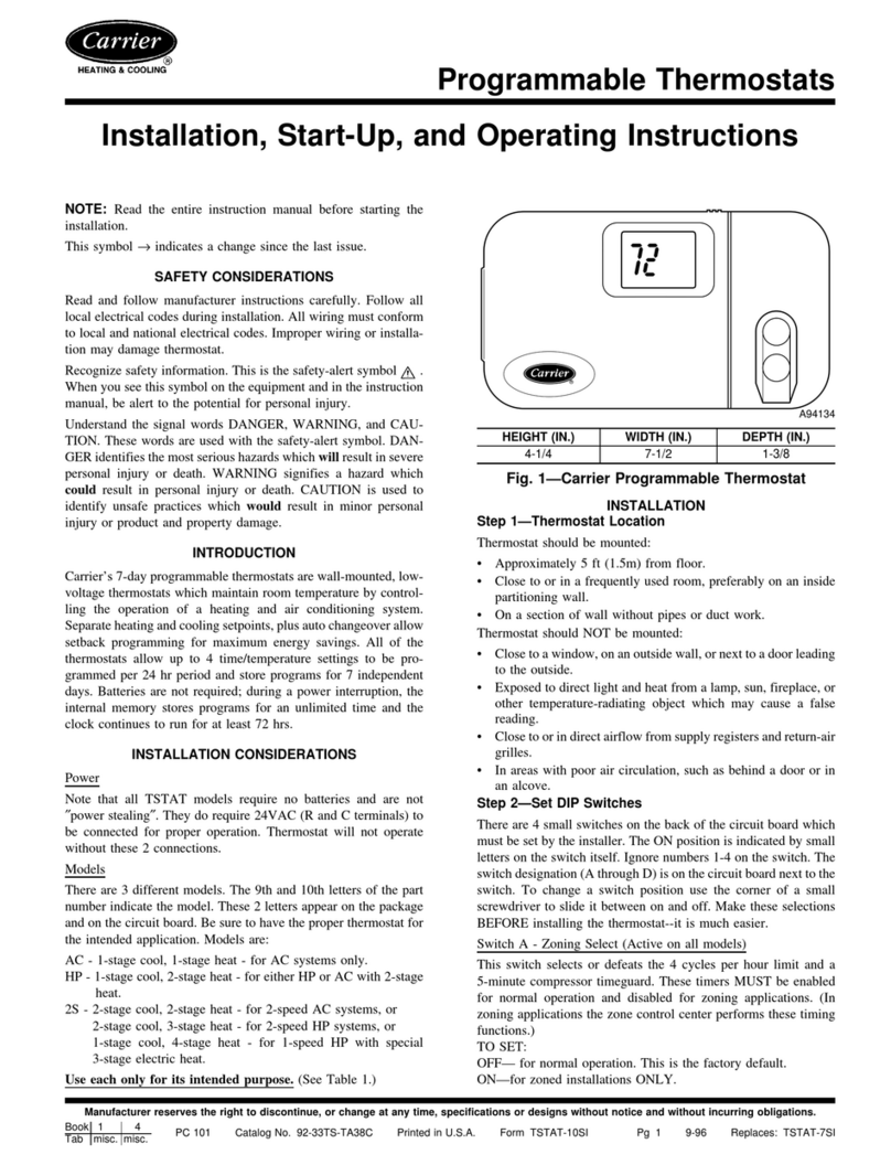
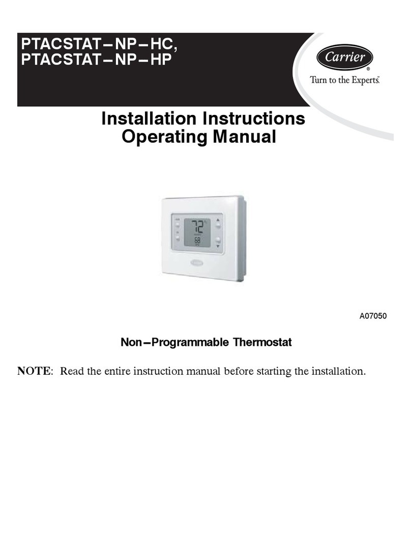
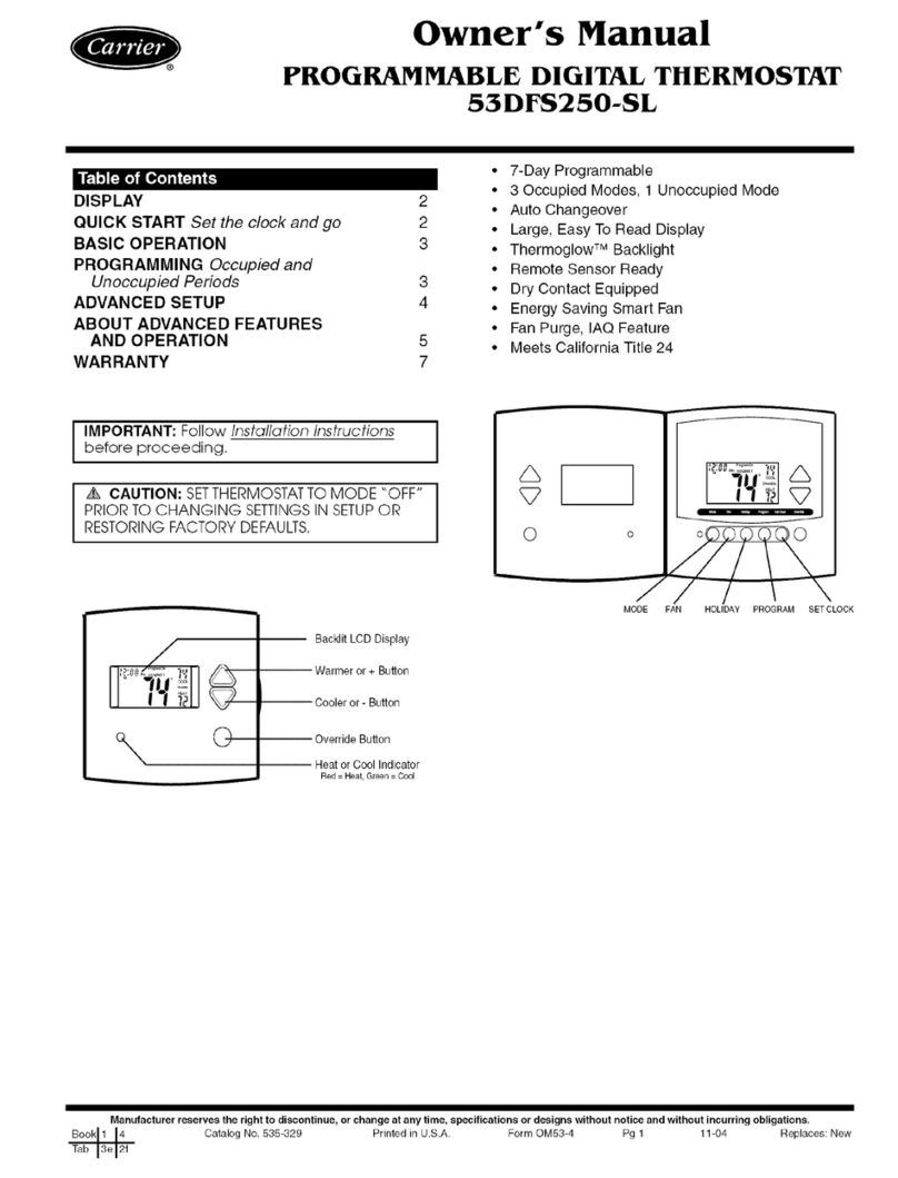
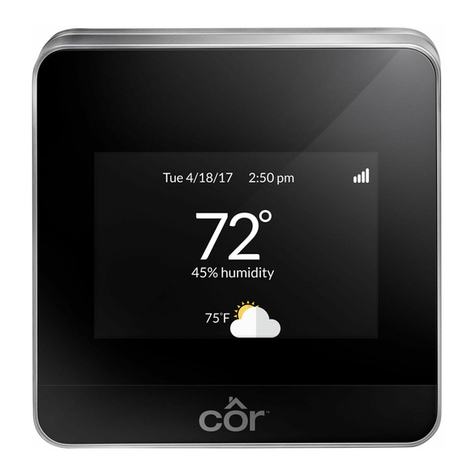
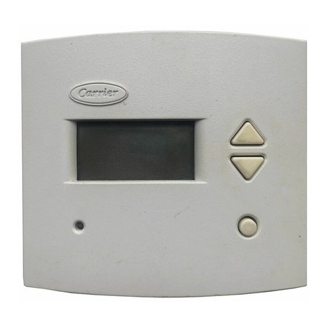
  9. Carrier 53DFST2-NP User manual

Carrier 53DFST2-NP User manual

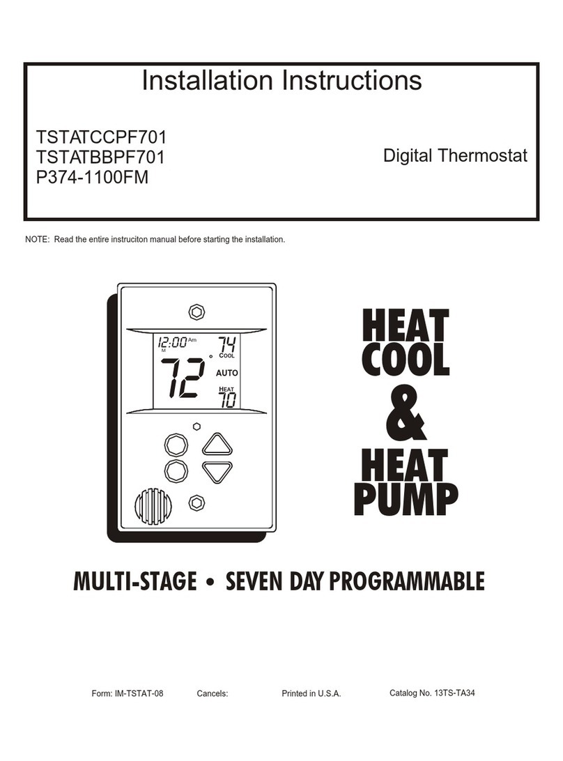
Installation Instructions
DIGITAL THERMOSTAT 53DFST2-NP
HeatCooland CoolingOnly
_i_ "jF'Jl I"J-'1:1:7±I-'_±'q/[e]_I
OOoVA
PROGRAMMABLE
STEP #1 PREPARATION
STEP #2 WIRE CONNECTIONS
SAMPLE WIRING DIAGRAM
STEP #3 TEST OPERATION
ADVANCED SETUP
ABOUT ADVANCED FEATURES
AND OPERATION
TROUBLESHOOTING
CALIBRATION
1
1
2
2
2
3
4
4
IIMPORTANT: Follow Installation Instructions carefully
CAUTION: DISCONNECT POWER TO THESYS-
TEM BEFOREINSTALLING THE NEW THERMOSTAT,
SERIOUSPERSONAL INJURY COULD RESULT,
A.
a.
C.
D.
Proper installation of the thermostat will be accom-
plished by following these step by step instructions. If
you are unsure about any of these steps, call a quali-
fied technician for assistance.
Assemble tools:
Flat Blade
Screwdriver Wire Cutter
and Stripper
Carefully unpack the thermostat. Save the screws,
bracket, and instructions.
Turn off the power to the system at the main fuse pan-
el. Most systems have a separate breaker for discon-
necting power to the indoor and outdoor units.
Refer to the chart below, or the wiring diagram that
follows for thermostat functions and corresponding
thermostat connectors.
FUNCTION
Lo Fan
Compressor
Heating
24 v Power
Common
Rev. Valve
Hi Fan
INSTALL ON THE
NEW THERMOSTAT
CONNECTOR MARKED
Gt
Y
H2
R
C
O*
G2
*Not applicable for use with Duct-Free Split heat pump systems.
This device complies with Part 15 of the FCC rules. Op-
eration is subject to the following 2 conditions: (1) This
device may not cause harmful interference, and (2) This
device must accept any interference received, including
interference that may cause undesired operation.
Manufacturer reserves the right to discontinue, or change at any time, specifications or designs without notice and without incurring obligations.
Catalog No. 02-DFC536SI Printed in U.S.A. Form 53-6SI Pg 1 11-05 Replaces: 53-3SI
8 Conductor 18 gage J[
unshielded came from
the thermostat to the
equipment
£E
LU
o
O-
:>
O
T_N_ CONNEC_ONS t
_ G, Y H_ O G_ 0
_ _ _ D D D D
2
Z CE I-- Z Z
,,< o ,,<, ,,< o
x (D o
o_ < I o
o
o
NOTE: For cooling only applications, H2 connection is not required,
[,._/ ::1_i'_ //:_',-_I[O]"2_-'__'_1/[o]_I
A.
B.
C.
Turn the power on to the HVAC (heating, ventila-
tion, and air conditioning) system.
Press the Mode button until the HEAT icon
appears on the display. Press the Up or Down but-
tons until the set point temperature is 2 degrees
above room temperature. The unit will turn on and
supply heat and the fan will turn on and run contin-
uously in low speed. Now increase the heat set
point to 4 degrees above room temperature. The
fan will run continuously in medium speed. Finally,
increase the heat set point to 6 degrees above
room temperature. The fan will run continuously in
high speed.
Press the Mode button until the COOL icon ap-
pears on the display. Press the Up or Down buttons
until the set point temperature is 10 degrees below
room temperature. The heat will turn off. Within
5 minutes the unit will turn on and supply cool air.
NOTE: Most equipment has a time delay between
cycles. This feature is debatable on the thermostat.
See the Advanced Setup section.
Press the Mode button
MOD_ While holding the Mode,
press the Override button
for 10 seconds to enter
OVERRInE Setup screens¸ reference.
IM PO RrrANT: Be sure to press and hold the overdde button
with the Mode button for a full ten seconds.
Adjust the lime of day
clock.
r,p: To change by hou,s, #,e_ and
ho_ the ovemd_* button #, and p,_ss
the up or dow,, buttons
12:0O_
NOTE: Each step number is located at
the top right corner of the display for easy
/
'1
Select the day of the
week.
Display On
Select display ope_et o_,
Full Display (On) orMinimal display (Off). ON
D,,_ay Off
Select Fan operation,
Fan On, Fan Auto, or Fan Off
on
(_ Select Heat Pump, On or Of L
off OFF
NOTE: Step 5 is not applicable for use with Duct-Free Split Heat Pump
Systems,
Adiuslthedeadband
from 1to 6deglees F.
(1 to6F)
Adjusl the minimum
differ_ between
cooling and heating
) set points.
(0 ¸¸to 6 F)
Select the cycles per
hour limit.
d=cycles per hour
I_mit defeated,
_ dl=d + defeat 5 rain,
Compressor lockout.
(d, dl, 2- 6)
On
Select the display back-
light always On, or Off
after 8 _eConds,
off
ON
C
SeleCt t_le[mostat
operatior_ in degrees
Fahrenheit or Oelsius.
F
Press the Mode button. While holding the Mode button in, press the Override
button to exit the Setup screens. If no buttons are pressed, the display will exit
the setup screens after 60 seconds,
Page 2
STEP NO.
1
2
3
4
5
6
7
8
9
10
Advanced Setup Table
DESCRIPTION RANGE FACTORY
DEFAULT
Time of day clock set 24 hour 12:00 Am
Day of the week Su - Sa Me
Display Blanking Off / On On
Fan Operation Auto /On Auto
Heat Pump* Off /On On
Deadband or Temperature swing 1 - 6 F 2 F
Forced minimum difference
heat/cool 0 - 6 F 2 F
Cycles per hour d, dl, 2 - 6 6
Thermeglow TM backlight Off / On On
Fahrenheit or Celsius F /C F
*Not applicable for use with Duct-Free Split Heat Pump systems,
• MINIMUM HEAT/COOL SET POINT DIFFERENCE
-- The Heat and Cool set points will not be allowed
to come any closer to each other than the value set
in the Advanced Setup section, Step 6. This mini-
mum difference is enforced during Auto changeover
and Program On operation.
• ENERGY SAVING SMART FAN -- If a manual fan
speed is selected, the fan will run continuously at all
times, except when in Off mode, and will only run if
there is a heating or cooling demand in unoccupied
periods.
• OVERRIDE -- Press the Override button during a
programmed, Unoccupied period to force the ther-
mostat into the Occupied 1 period, temporarily, for
up to 4 hours. If the Override button is pressed dur-
ing an Occupied period, the thermostat will be
forced into an Unoccupied period and the Occupied
period (1,2 or 3), it was forced out of will be turned
off, only for that day.
During Override periods the set points may be
adjusted, but they will not be remembered after
Override period ends.
• KEYPAD LOCK-- To prevent unauthorized use of
the thermostat, the front panel buttons may be dis-
abled. To disable or 'lock' the keypad, press and
hold the Mode button. While holding the Mode but-
ton, simultaneously press the Up and Down but-
tons. The Locked icon will appear on the display.
Press all 3 for _ (_
Keypad Lockout _ (_ "_'
MODE O
_C
_._
Lock_
To unlockthe buttons, again press and hold the
Mode button. While holding the Mode button, simul-
taneously press the Up and Down buttons. Locked
will disappear from the display.
DISPLAY BLANKING -- The thermostat display
may be configured in Advanced Setup section,
Step 3, to always be visible as normally expected,
or may be selected Off. When selected Off, only the
time of day will appear until a button is pressed.
When a button is pressed the full, normal display
will appear and then revert to display the time of day
only, after approximately 10 seconds.
• DUAL SET POINT BEHAVIOR -- The adjustable
set point range is: 35 to 99 degrees in Fahrenheit
and 7 to 35 degrees in Celsius. When in the modes
Heat or Cool, this adjustable range is unhampered.
When adjusting any Auto mode, including program-
ming Occupied and Unoccupied set points, the ther-
mostat will not allow the Heat set point to get closer
to the Cool set point than the value programmed as
the minimum difference in the Advanced Setup sec-
tion, Step 7.
When entering the Auto mode from Cool mode, the
Heat and Cool set point temperatures will remain
spread apart by the amount that they were
adjusted, prior to entering Auto mode.
For example: If the Cool set point was set to 80 F
while in the Cool mode and the Heat set point was
adjusted to 70 F while in the Heat mode, upon
entering the Auto mode the Cool and Heat set
points would be 80 F and 70 E Both set point tem-
peratures would then move up and down together,
(in this example spread by 10 degrees), by pressing
the Up or Down buttons.
To move the Heat and Cool set points closer
together, enter the Cool or Heat mode by pressing
the Mode button, then adjust the set point(s) closer
together. Heat is limited to how close it can come to
Cool in the Advanced Setup section, Step 7.
• FACTORY DEFAULTS -- Before restoring factory
defaults, set thermostat to OFF mode. If, for any
reason it is desirable to return all stored settings
back to the factory default settings, press the Mode
button. While holding the Mode button in, press the
Down button for 2 seconds. All icons will appear.
Press and hold the Override button until Fd
appears. All icons will appear. Press and hold in the
Fan button until Fd appears. This resets all factory
settings. To calibrate room temperature, see the
Calibration section on page 4.
"! __ °Aoto
• ram. ILl
00oV A
Page 3
I|;[o]lJ :] !:_: [oIo] /I+[_+
SYMPTOM
When not using a
common wire the air
conditioning equip-
ment tries repeatedly
to turn on, but cannot.
At times the display
dims or disappears.
CAUSE
There is not enough
_ower available to
"power share."
REMEDY
Connect a 270 ohm,
10 watt power resis-
tor at the unit as
shown below.
For Problem A/C
For Problem Heat
The air conditioning The compressor timer See the Advanced
does not attempt to lockout may prevent Setup section to
turn on. the air conditioner defeat the cycles per
from turning on, for a hour and compressor
_eriod of time. timeguard.
The display is blank. Lack of proper power. Check for 24 vac
between R and C.
The air conditioning The cooling set point Press the down arrow
does not attempt to is set too high. until the cooling set
turn on. point is 10 degrees
lower than the room
temperature.
The heating does not The heating set point Press the up arrow
attempt to turn on. is set too low. until the heating set
point is 10 degrees
higher than the room
temperature.
The strip heater turns Heat pump is incor- Select heat pump
off well before reach- rectly selected "on" in "off" during Advanced
ing set point, the Advanced Setup. Setup programming.
See the Advanced
Setup section.
CALIBRATION: Every thermostat is calibrated before it
leaves the factory. Under normal circumstances there will
never be a need to recalibrate the thermostat. To accom-
modate special needs, the thermostat may be recalibrat-
ed following these steps:
1. While holding the Mode button in, press the down
button for 5 seconds. After all the icons in the dis-
play appear, release the buttons.
2. Press the Mode button twice.
3. Press the up or down buttons until the flashing
number equals the current room temperature.
4. Press the Mode button to return to normal
operation.
Copyright 2005 Carrier Corporation
Manufacturer reserves the right to discontinue, or change at any time, specifications or designs without notice and without incurring obligations.
Catalog No. 02-DFC536SI Printed in U.S.A. Form 53-6SI Pg 4 11-05 Replaces: 53-3SI

Other Carrier Thermostat manuals

Carrier Totaline P374-2800 User manual

Carrier

Carrier Totaline P374-2800 User manual

Carrier 33CS Manual

Carrier

Carrier 33CS Manual

Carrier ComfortVu Plus TBPL-H Operating instructions

Carrier

Carrier ComfortVu Plus TBPL-H Operating instructions

Carrier EDGE Pro 33CS2PPRH-03 User manual

Carrier

Carrier EDGE Pro 33CS2PPRH-03 User manual

Carrier BASE SERIES PROGRAMMABLE THERMOSTATS TB-PAC User manual

Carrier

Carrier BASE SERIES PROGRAMMABLE THERMOSTATS TB-PAC User manual

Carrier Aquazone 50QE900-NPWS User manual

Carrier

Carrier Aquazone 50QE900-NPWS User manual

Carrier MODULINE 37HS Datasheet

Carrier

Carrier MODULINE 37HS Datasheet

Carrier KSACN0901AAA User manual

Carrier

Carrier KSACN0901AAA User manual

Carrier Non-Programmable Thermostats Instructions and recipes

Carrier

Carrier Non-Programmable Thermostats Instructions and recipes

Carrier 33CS User manual

Carrier

Carrier 33CS User manual

Carrier Programmable Thermostats Instructions and recipes

Carrier

Carrier Programmable Thermostats Instructions and recipes

Carrier Infinity SYSTXCCITW01 User manual

Carrier

Carrier Infinity SYSTXCCITW01 User manual

Carrier Comfort Touch-n-Go User manual

Carrier

Carrier Comfort Touch-n-Go User manual

Carrier Cor User manual

Carrier

Carrier Cor User manual

Carrier edge Performance TP PHP01 A Series User manual

Carrier

Carrier edge Performance TP PHP01 A Series User manual

Carrier Comfort TC-WHS01-BLK User manual

Carrier

Carrier Comfort TC-WHS01-BLK User manual

Carrier AQUAZONE 50QE900 User manual

Carrier

Carrier AQUAZONE 50QE900 User manual

Carrier User interface Comfort Module Series Operating manual

Carrier

Carrier User interface Comfort Module Series Operating manual

Carrier 33CS2PPRH-02 User manual

Carrier

Carrier 33CS2PPRH-02 User manual

Carrier Comfort series User manual

Carrier

Carrier Comfort series User manual

Carrier N-MC-FC Operational manual

Carrier

Carrier N-MC-FC Operational manual

Carrier A07049 User manual

Carrier

Carrier A07049 User manual

Carrier Cool Share Web-Programmable Thermostat User manual

Carrier

Carrier Cool Share Web-Programmable Thermostat User manual

Carrier TSTAT Instructions and recipes

Carrier

Carrier TSTAT Instructions and recipes

Popular Thermostat manuals by other brands

Honeywell FocusPRO TH6220D owner's manual

Honeywell

Honeywell FocusPRO TH6220D owner's manual

OJ Electronics OCC3 user manual

OJ Electronics

OJ Electronics OCC3 user manual

Polypipe UFHPROGW manual

Polypipe

Polypipe UFHPROGW manual

suntouch SunStat Core 108201 user manual

suntouch

suntouch SunStat Core 108201 user manual

LK Systems SR 310 installation instructions

LK Systems

LK Systems SR 310 installation instructions

Grasslin famoso 1000 rf manual

Grasslin

Grasslin famoso 1000 rf manual

Julabo F12-MC operating manual

Julabo

Julabo F12-MC operating manual

Pfannenberg FLZ 520 Instructions for use

Pfannenberg

Pfannenberg FLZ 520 Instructions for use

SyxthSense Tempora TCP-GIO-BI03 manual

SyxthSense

SyxthSense Tempora TCP-GIO-BI03 manual

TENZA CPT11 installation manual

TENZA

TENZA CPT11 installation manual

Twitoplast TQMS RC11 manual

Twitoplast

Twitoplast TQMS RC11 manual

Honeywell Home T4 Pro user guide

Honeywell Home

Honeywell Home T4 Pro user guide

Wamup TSTAT user guide

Wamup

Wamup TSTAT user guide

Crestron CHV-TSTATEX Operations & installation guide

Crestron

Crestron CHV-TSTATEX Operations & installation guide

dixell XR20CX Installing and operating instructions

dixell

dixell XR20CX Installing and operating instructions

Elko EKO09765 user guide

Elko

Elko EKO09765 user guide

Honeywell CM702 Product specification sheet

Honeywell

Honeywell CM702 Product specification sheet

Emerson 1F83-0422 instructions

Emerson

Emerson 1F83-0422 instructions

manuals.online logo
manuals.online logoBrands
  • About & Mission
  • Contact us
  • Privacy Policy
  • Terms and Conditions

Copyright 2025 Manuals.Online. All Rights Reserved.