Cartek BEAR 80-2000T User manual

WHEEL BALANCER
Model: 80-2000T
Operation manual

Wheel balancer 80-2000T. Operation Manual p.2
2

Wheel balancer 80-2000T. Operation Manual p.3
3
CONTENTS
1 WHEEL BALANCER APPLICATION ........................................................................... 5
2 TECHNICAL DATA ...................................................................................................... 6
3 ACCESSORIES ........................................................................................................... 7
4 STRUCTURE AND PREPARATION FOR OPERATION .............................................. 9
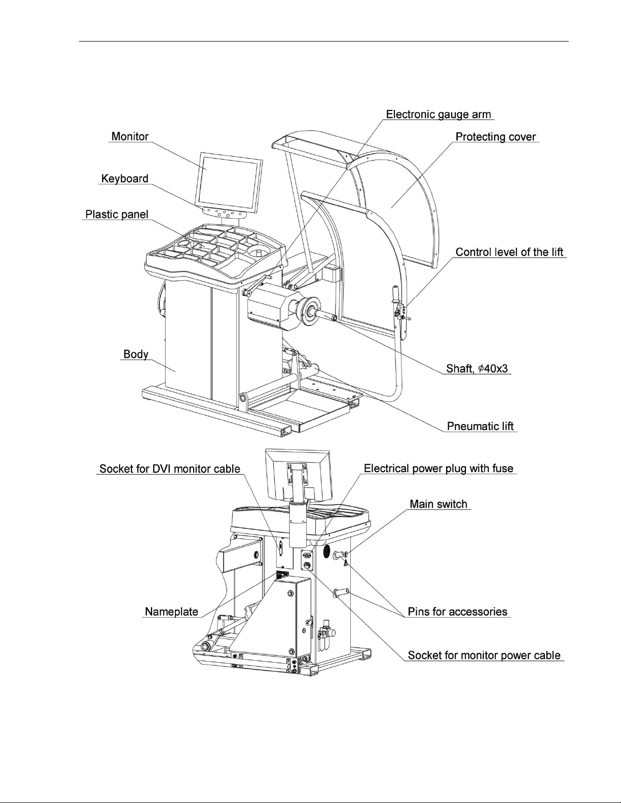
4.1 General machine structure................................................................................................ 9
4.2 Preparation of the machine for operation ..................................................................... 10
4.3 Control and display elements ......................................................................................... 13
4.4 Using the menu ................................................................................................................ 14
4.5 Switching the wheel balancer......................................................................................... 14
5 WHEEL BALANCING ................................................................................................ 16
5.1 Wheel balancing procedure ............................................................................................ 16
5.2 Wheel mounting ............................................................................................................... 16
5.2.1 Truck-car wheel mounting ........................................................................................... 16
5.2.2 Motor-car wheel mounting ........................................................................................... 17
5.3 Entering the type of the wheel: motor car or truck car................................................ 18
5.4 Wheel parameters input .................................................................................................. 18
5.5 Imbalance measurement ................................................................................................. 20
5.6 Weight setting................................................................................................................... 20
6 EXAMPLES OF WHEEL BALANCING ...................................................................... 22
6.1 Standard wheel balancing............................................................................................... 22
6.2 Alloy wheel (ALU) balancing........................................................................................... 23
7 ADDITIONAL POSSIBILITIES ................................................................................... 25
7.1 Effective alloy wheels balancing - SmartALU technology........................................... 25
7.2 Split – «hidden weight» ................................................................................................... 26
7.3 Effective work of three operators................................................................................... 27
7.4 Optimization...................................................................................................................... 27
7.5 Adaptor imbalance compensation ................................................................................. 28
7.6 Manual parameters setting.............................................................................................. 29
7.7 Report................................................................................................................................ 29
7.8 Wheel balancing recommendations............................................................................... 29
8 WHEEL BALANCER SETTING ................................................................................. 30
8.1 Parameters setting........................................................................................................... 30
8.1.1 Rounding: yes, no ........................................................................................................ 30
8.1.2 Null threshold (car): 0…15 ........................................................................................... 30
8.1.3 Null threshold (truck): 15…45 ...................................................................................... 31
8.1.4 Safety start: yes, no ..................................................................................................... 31
8.1.5 Stick-on weight setting: 6 h, 12 h ................................................................................ 31
8.1.6 SmartALU: yes, no ...................................................................................................... 31
8.1.7 Autoswitch to the «New wheel»: yes, no ..................................................................... 31
8.2 Shaft: Testing and calibration......................................................................................... 31
8.2.1 Shaft calibration testing ............................................................................................... 31
8.2.2 Shaft calibration ........................................................................................................... 32
8.3 Gauge arms: testing and calibration.............................................................................. 32

Wheel balancer 80-2000T. Operation Manual p.4
4
8.3.1 Gauge arm diagnostics ................................................................................................ 32
8.3.2 Gauge calibration ......................................................................................................... 32
8.4 Imbalance sensors: testing and calibration ..................................................................33
8.4.1. Imbalance measurement accuracy check (simplified) ................................................ 33
8.4.2 Imbalance sensors calibration (truck-car) .................................................................... 33
8.4.3 Imbalance sensors calibration (motor-car) .................................................................. 34
9 TROUBLESHOOTING ................................................................................................ 35
9.1 Messages...........................................................................................................................35
9.2 Other fault events and remedies.....................................................................................36
10 MAINTENANCE AND SAFETY REQUIREMENTS .................................................. 37
10.1 Maintenance ....................................................................................................................37
10.2 Safety requirements .......................................................................................................37
10.3 Instructions for emergency cases ................................................................................38
11 STORAGE AND TRANSPORTATION ...................................................................... 38
11.1 Storage.............................................................................................................................38
11.2 Transportation.................................................................................................................38
11.3 Information on recycling................................................................................................38
12 MANUFACTURER’S WARRANTY ........................................................................... 39
13 CERTIFICATE OF ACCEPTANCE ........................................................................... 39
Appendix A ................................................................................................................... 39
Appendix B - Electric scheme ..................................................................................... 41
Declaration of conformity .................................................. Error! Bookmark not defined.

1 WHEEL BALANCER APPLICATION
1.1 The wheel balancer 80-2000T (hereinafter referred to as the “machine”), is designed
for balancing truck car wheels and motor car wheels with rim diameter up to 30”, width – up to
20” at forwarding companies, vehicle service and repair stations, stations and points of vehicle
diagnostics and vehicle repairing plants.
1.2 The machine is equipped with
- pneumatic lift;
- adapters kit for trucks wheels by Haweka;
- color LCD-monitor ensuring high quality image;
- electronic gauge arm for automatic input of diameter and distance.
High accuracy of imbalance measurements allows balancing standard wheels by one
cycle. SmartALU function raises the operation efficiency of the machine when balancing a set of
wheels with the help of stick-on weights.
For exacting customers there exists the Split function (behind-the-spoke-weight
placement) and optimization of tyre position on the rim.
A thoroughly developed interface facilitates the machine mastering and makes further
operation convenient and efficient. There is also a possibility of three operators’ working on the
machine.
1.3 Imbalance measurements may be fulfilled automatically while lowering the wheel
cover. After measurements the wheel braking is fulfilled automatically.
1.4 The machine is equipped with overvoltage protection device in the supply mains
(Power Guard technology).
1.5 For the machine functionality enhancement accessories and attachments of other
producers, for example Haweka (Germany), Femas (Italy) may be mounted on the shaft. In
particular, adaptors for motorcycle wheels mounting, adaptors for wheels without the central
hole.
The shaft diameter is 40 mm, thread pitch is 3 mm.
1.6 The machine is driven by 3-phase electric motor. It’s controlled by the intellectual drive
circuit (S-Drive technology). This ensures:
- low vibration level;
- steady rotation speed during measurements;
- automatic turn to the place of the weight setting;
- gradual acceleration;
- soft electronic braking and partial braking during wheel mounting/dismounting without
impact effect on the shaft.
1.7 Wheel balancing is fulfilled by taking one measurement for both correction planes with
simultaneous indication of placing locations and corrective weights masses.

Wheel balancer 80-2000T. Operation Manual p.6
6
2 TECHNICAL DATA
2.1 Machine type Stationary
2.2 Wheel weight range, kg 10÷200
2.3 Maximum wheel outer diameter, mm 1200
2.4 Absolute error of imbalance measuring, gr*mm
- motor car wheels
- truck car wheels
1080
4200
2.5 Imbalance measurements range, gr*мм…
- motor car wheels
- truck car wheels
0…31000
0…90000
2.6 Measurement cycle time, sec., max
- motor car wheels
- truck car wheels
12
50
2.7 Power supply (191…242) VAC,
(50…60) Hz
2.8 Power consumption, W, max 350
2.9 Weight of the machine, kg, max 280
2.10 Overall dimensions with lowered/raised wheel cover, mm,
max
Length 2100
Width 1700
Height 1700
2.11 Shaft rotation speed, RPM
- motor car wheels
- truck car wheels
160-170
90-110
2.12 Air supply, Bar 8…10
2.13 Operating temperature range, С +10 +35
2.14 Relative air humidity, %, max. 80

Wheel balancer 80-2000T. Operation Manual p.7
7
3 ACCESSORIES
Delivery set is specified in Table 3.1.
T a b l e 3.1
No Description Quantity,
items
Notes
1 Wheel balancer 1
2 Operations manual 1
3 Threaded shaft (40x3X140) with bolt for
shaft mounting
1 40х3х180, 40х3х240
on request
4
Adapter six-sided 1
Depending on
execution of a
threaded shaft bolt
5 Monitor bracket 1
6 Monitor: input DVI, VESA mount 75x75 or
100x100
1 on request
7 Bracket of the cover 1
8 Mobile part of cover 1
9 Motionless part of cover 1
10 Nut with ring 1
11 Gauge calibre 1
12 Weight pliers 1
13 Power supply wire 1
14 DVI cable 1 Depending on
monitor set
15 Packing 1
16 Control lever of the lift 1
17 5-lever adapter 1 Set for truck car
wheels installation

Wheel balancer 80-2000T. Operation Manual p.8
8
18 4-lever adapter 1
19 Thrust ring 1
20 Lock bolt with nut 5
21 Caliper 1
22 Plastic scrapper for adhesive balance
weights
1
23 Bolt M10 with washer (for fastening of the
thrust ring)
2
24 Bolt M6 with washer (for fastening of the
monitor bracket)
2
25 Screw M4 with washer (for fastening of
the monitor)
4
26 Bolt M10x20 with washer (for fastening of
the bracket of the cover)
4
27 Bolt M8x20 with washer (for fastening of
the motionless part of cover)
4
28 Bolt M10x75 with washer and nut (for
fastening of the mobile part of cover)
2
29 Silica Gel 1 kg at transport by sea
Set N1 For motor car wheels installation (on request)
30 Cone 78...114 1
31 Cone 62…82 1
32 Cone 43...70 1
33 JEEP set (cone 97...160 with ring) 1
34 Quick Nut with plastic ring, cup and
rubber ring
1
35 Packing 1

Wheel balancer 80-2000T. Operation Manual p.9
9
4 STRUCTURE AND PREPARATION FOR OPERATION
4.1 General machine structure
Figure 4.1
Figure 4.1 shows the structure of the machine.

Wheel balancer 80-2000T. Operation Manual p.10
10
Pneumatic lift is designed for setting and removing wheels with weight up to 200 kg on
spindle shaft.
Pneumatic lift consists of guides that provide horizontal plane displacement of forklift grab,
body and pneumatic cylinder, which is controlled by pneumatic switch, located on control lever.
Air preparation system (see Figure 4.5) is located on machine body and consists of:
- moisture eliminator with settling;
- air-oil lubricator;
- pressure regulator for limitation of compressed air pressure in pneumatic system;
- pressure gauge for compressed-air control in pneumatic system.
4.2 Preparation of the machine for operation
4.2.1 Unpack the machine. During the unpacking be careful not to damage the machine by
unpacking tools.
After unpacking make visual check of the machine in order to find damages, which may
occur during transportation, read carefully technical documentation enclosed, check the
availability of accessories in accordance with the delivery set.
After transportation or storage of the machine at an air temperature lower than +5Сit’s necessary to
keep the machine at a temperature of (2510) Сduring minimum 4 hours before unpacking.
4.2.2 Place the machine on an even rigid foundation, admissible deviation of the
foundation from the horizontal line is 0.5° (8 mm per 1m), so that all supports of the machine
touch the foundation. It is achieved by means of 2 adjustable supports (Fig. 4.2)
Figure 4.2
For safe and convenient operation of the machine it’s recommended to locate it minimum
700 mm from the walls.
It’s prohibited to locate the machine near sources of vibration, heat and electromagnetic
fields, as it may reduce the accuracy of measurements of the machine.
4.2.3 Assemble shaft in accordance with Figure 4.3. Clean the machine spindle hole and
shaft from preserving grease by rag moistened in petrol or white spirit. In accordance with
Figure 4.3a set shaft 2 on machine spindle 1 fastening it by bolt 3 with torque 40 Nm, using
adapter six-sided if necessary. During removal of the shaft it’s allowed to tip slightly on the
surface “B” (on horizontal surface) by a rubber or wooden hammer.
Do not apply force along the spindle axis (for example, during transportation, during wheel mounting
and dismounting)!
Figure 4.3 - Shaft assembling

Wheel balancer 80-2000T. Operation Manual p.11
11
4.2.4 Mount lift control lever using 4 bolts in accordance with Figure 4.4.
Figure 4.4
4.2.5 Connect small-diameter pneumatic tubes, having aligned marks on tubes with marks
on fittings, as shown on Figure 4.5. Connect air supply hose to the inlet connection.
Recommended operation pressure is 8 to 10 Bar.
4.2.6 Adjust lift horizontal propel effort by means of a nut. Move the nut down to increase
propel effort, and vice versa, Figure 4.5.
4.2.7 Set protective cover in accordance with Figure 4.6.
Mount bracket of the cover on the casing of the machine with bolts M10x20 and washers
10. Mount motionless part of cover on the bracket of the cover with bolts M8x20 and washers 8.
Mount mobile part of cover on the axis bracket of the cover with bolts M10x75, washers 10 and
nuts M10.
Figure 4.5
Marks
Nut
Inlet connection

Wheel balancer 80-2000T. Operation Manual p.12
12
Figure 4.6
4.2.8 Set monitor in accordance with Figure 4.7:
fasten bracket 3 by screws M6 1;
fasten monitor to bracket 3 by screws M4 2;
plug DVI cable to monitor socket and socket 11 on machine body, shown on Figure 4.1.
4.2.9 Check the mains voltage conformity to the voltage indicated on the machine
nameplate and on monitor nameplate.
4.2.10 Connect monitor to socket 15 on machine body, shown on Figure 4.1, or to supply
mains, equipped with the mains socket with the grounding contact according to monitor
maintenance documentation.
4.2.11 Connect the power supply cable to the machine jack, located on the rear panel of
the machine body (Figure 4.1) and to the supply mains equipped with the mains socket with the
grounding contact.
Connecting machine and monitor to the supply mains without grounding is dangerous for the
personnel and may reduce the accuracy of measurements and damage the machine!
Figure 4.7 – Monitor setting
4.2.11 Fulfill the shaft balancing testing and balance standard wheel for testing after the
machine installation.

Wheel balancer 80-2000T. Operation Manual p.13
13
4.3 Control and display elements
Figure 4.8 shows control console and the example of display image.
1 - information field; 2 - current state; 3 - main field; 4 - panel of key names; 5 - soft keys icons; 6 - soft
keys; 7 - shaft stop key; 8 - shaft start and imbalance measurement key
Figure 4.8
The information field 1 is located in the upper part of the display. Meanings of the
information field icons:
The icons «Weights setting scheme» and «Operator No» are always activated and show
the current state.
The rest icons indicate the mode and sign state. Contrast icon indicates activated sign or
mode, pale icon indicates deactivated sign or mode.
There are five soft keys 6 on a keyboard. Meaning of the soft keys depends on machine
state. Each soft key's function is shown on the display as a text message and as an icon above
the soft key.
Some functions of the soft keys are described below:
- execute a menu item, finalize parameters change and save the changes;
- weights setting scheme and unrounded weights values;
- diagnostic message sign;
- wheel type: motor-car;
- wheel type: truck-car;
- adaptor compensation mode;
- SmartALU mode sign;
- operator No.

Wheel balancer 80-2000T. Operation Manual p.14
14
- interrupt any action, finalize parameters change and restore previous settings;
- move to the previous level of the menu;
- change parameter setting;
- choose screen elements (menu item, weights setting scheme,
etc.)
Further the soft keys are indicated in the frame, for example OK .
Functions of the other keys:
START - shaft turning and imbalance measurements start
STOP - emergency wheel stop during the imbalance measurement, temporary brake
engagement while wheel dismounting and mounting.
4.4 Using the menu
Menu is used for operating some machine functions.
To enter the main menu in the «New wheel» state press MENU . The display shows
a list consisting of some items, Figure 4.9.
To choose a menu item press UP DOWN , mark the item you need and press
EXECUTE .
Figure 4.9
Other menu items meaning and their usage will be described in other sections.
4.5 Switching the wheel balancer
Before switching it’s necessary to make sure that the gauge arm is in the initial position
(Figure 4.10).
Move the mains switch to the position ON.
On the monitor screen for some seconds there will be information on version number of
the machine, then - page of a choice of language in the form of several flags. The current
choice is shown by a brighter flag in the frame. Press to change chosen setting or ,

Wheel balancer 80-2000T. Operation Manual p.15
15
to finalize choice press . If changes are not necessary, the machine tool in some seconds
automatically leaves this state. The machine will be in the «New wheel» state, Figure 4.11.
Figure 4.10 – Initial gauge arm position Figure 4.11 – «New Wheel» state

Wheel balancer 80-2000T. Operation Manual p.16
16
5 WHEEL BALANCING
5.1 Wheel balancing procedure
Balance the wheel in accordance with the following procedure.
- activate the machine state «New wheel»;
- prepare and mount the wheel (5.2);
- in case of necessity change the type of balanced wheel: motor car or motorcycle wheel
(5.3);
- enter wheel data if necessary (5.4);
- fulfil the imbalance measurement (5.5);
- set weights if necessary (5.6);
- make check measurement (5.5).
5.2 Wheel mounting
While wheel mounting it’s necessary to remember that the machine should be kept clean. Avoid dust
and moisture penetration inside the machine, water pouring and splashing on control panels and
openings in the machine body.
5.2.1 Truck-car wheel mounting
Before balancing, clean the wheel to be balanced, and remove all weights, set
previously. Mount the wheel on the shaft in accordance with figures 5.1 depending on the wheel
rim design.
Wheels with hub bore diameter 281 mm shall be mounted as shown on Figure 5.1. Fasten
the thrust ring on drive shaft by means of two bolts.
Figure 5.1 Figure 5.2
Using control lever, initialize lift for wheel loading.
Roll the wheel to the lift platform.
Lift the wheel by moving pneumatic switch lever up as shown on Figure 5.2; make sure
that the wheel is in alignment with spindle shaft. Then move the lift with the wheel to spindle
cup with thrust ring, mount the wheel on thrust ring (diameter 281 mm) and fasten it by means
one of two adapters and a nut.
Tighten up the nut in three positions, each time rotating the wheel by the third part of the
turn. Make sure that the wheel is mounted properly in all positions: stand near the shaft and pull
on the wheel.
Move pneumatic switch lever down to lower forklift grab and move it to the machine body.
Wheel removal shall be fulfilled in reverse sequence.

Wheel balancer 80-2000T. Operation Manual p.17
17
5.2.2 Motor-car wheel mounting
Before balancing, clean the wheel to be balanced, and remove all weights, set
previously. Mount the wheel on the shaft in accordance with figures 5.3 depending on the wheel
rim design.
а – cone from inside b – cone from inside with shaft spacer
c - cone from outside d - JEEP set
e – flange plate setting f – daps for adaptors fixing
Figure 5.3 – Wheel mounting
It is recommended to mount the wheel with cone outside, Figure 5.3b in case of correct
construction of the wheel and quality of the outer margin of the opening. In this case wheel
centering is more correct and shaft and nut thread wear is much less.
Wheel mounting with shaft spacer delivered on request (Figure 5.3b) is recommended
when the cone is mounted from inside, if the cone is set deeply in the wheel opening and
insufficiently compresses the spindle spring while tightening up the wheel nut. The stronger the
spring is compressed; the better is the wheel centering.
Wheel mounting on the flange plate adapter delivered on request (Figure 5.3e) imitates the
wheel fastening on the car hub and allows balancing the wheel more precisely. Initially, it’s
necessary to fasten the flange on the wheel, and then mount the wheel with the flange on the
machine spindle.

Wheel balancer 80-2000T. Operation Manual p.18
18
Parameters of the flange holes arrangement for wheel fastening bolts are given in
table 5.1. The list of car models the wheels of which have the same fastening parameters is
given in Appendix A.
Table 5.1 Flange holes parameters
Diameter of bolts arrangement, mm Number of bolts, pieces
139.7 5
115 5
170 3
108 5
For mounting motorcycle wheels and wheels without the central hole it’s necessary to use
special adaptors to be purchased separately. The adaptors should be mounted using daps or
holes 1 in the shaft cup shown in Figure 5.3f.
After mounting the adaptors, fastened on the shaft in fixed position it’s necessary to fulfil
the procedure of their imbalance compensation according to clause 7.5. Deactivate the adaptor
compensation mode after removing the adaptor.
The adaptor compensation procedure should be fulfilled before the wheel mounting!
If the adapter's imbalance does not exceed 3 gr adaptor compensation is not necessary.
While mounting the wheel it’s initially recommended to draw it slightly by clamping nut
leaving a small end float. Then turn the wheel for one revolution, rocking it by hands. After that
completely tighten the nut. For better wheel centering it is recommended to raise it by left hand
while tightening the nut.
In order to facilitate the wheel mounting and dismounting in mode «New wheel» it’s possible to
activate the shaft braking mode by pressing the button STOP .
5.3 Entering the type of the wheel: motor car or truck car
Check the current type of the wheel shown by the icons in the information field
and . If it's necessary to change the wheel type press the button CAR .
5.4 Wheel parameters input
If it is not necessary to change the parameters for example when the wheel is exactly the same as the
previous one - you can immediately proceed to imbalance measuring.
To enter dimensions it is necessary to measure diameter and distance by means of the
electronic gauge arm in «New wheel» state.
If the gauge arm doesn't reach the rim use gauge arm extender according to 7.6.
For measurement move the gauge arm close to the rim according to Figure 5.4a. The
image will appear on the display, shown in Figure 5.4b. Wait for a sound signal. Move the
gauge arm into the initial position.

Wheel balancer 80-2000T. Operation Manual p.19
19
а б
Figure 5.4 – Taking measurements by the gauge arm
When you press ESC the dimensions will return to the initial values as before the
measurement start and the machine will be switched over to the state «New wheel».
After measuring diameter and distance the machine automatically switches into weight
setting scheme and width input.
The current scheme is marked on a display by the coloured frame, Figure 5.5.
For choosing another scheme press ALU and ALU .
Figure 5.5 – Choosing the weight setting scheme
If after choosing the scheme the WIDTH keys are activated (contrast) you should enter
the wheel width.
Measure the wheel width by the caliper, Figure 5.6. Enter width by pressing
WIDTH and WIDTH .

Wheel balancer 80-2000T. Operation Manual p.20
20
Figure 5.6 - Measuring wheel width with a caliper
When you press ESC the dimensions will return to the initial values as before the
measurement start and the machine will be switched over to «New wheel» state.
After entering the parameters you can measure imbalance.
5.5 Imbalance measurement
For the imbalance measurement lower the cover or press the button START with the
lowered cover. Wait for the complete wheel stop. Raise the cover.
For emergency stop without completing the measurement press the button STOP .
During measurements mechanical effects on the machine are not allowed, it’s not allowed to lean on
the machine body, take from the machine and put on the machine accessories, tools and other objects.
ATTENTION! Before the first measurement after switching the machine, the shaft automatically
rotates on one turn with small speed.
If the automatic transition into the «New wheel» is enabled (8.1.7) in case of «zero» results
in both dimensions the machine switches from weights setting state into «New wheel» state.
5.6 Weight setting
The machine will be switched over to the weight setting state after the imbalance
measurement and wheel stop. The shaft with the wheel will automatically turn to a desired
position and weights masses will be shown on a display, Figure 5.7.
а – set the clip-on weight of 150 gr. on the left b – set the stick-on weight of 150 gr. on the left in
"6 h" position
Figure 5.7
After the wheel stop in the desired position the mass of that weight which is to be set now
is framed and displayed by yellow colour.
To set the clip-on weight apply the weight to the rim in the position “12 h” , as it’s shown
in Figure 5.8, and fix it on the rim by slight knocking by the tool.
Table of contents
Popular Wheel Balancer manuals by other brands

Cormach
Cormach MEC 810VD-VDL-VDBL Use and maintenance manual

MANATEC
MANATEC Fox 3D Smart Mobile PT Service manual

Cormach
Cormach MEC 200 TRUCK Use and maintenance manual

Hofmann
Hofmann Snap-on Y2k Service manual

Rotary
Rotary R544PLUS Instruction, use and maintenance manual

Atlas
Atlas 501 quick start guide

Snap-on Incorporated
Snap-on Incorporated MICROSCAN III quick start guide

Bosch
Bosch FWA 4630 Original instructions

WilTec
WilTec XPOtool 51742 Operation manual

CAR-MON
CAR-MON LFT Series quick start guide

HENNESSY INDUSTRIES
HENNESSY INDUSTRIES coats ProRide Diagnostic manual

Costway
Costway TL31130 user manual