IDEAL IWA-60-1500-K User manual

V. 1.1.17
3D Wheel Aligner
Manual
IWA-60-1500-K

IDEAL 60-1500 Wheel Aligner Manual
Table of Contents
———————————————————————————————————————-
I. Introduction...........................................................................................................3
1.1 Warning..................................................................................................................3
1.2 Safety warning.......................................................................................................3
II. Getting Started......................................................................................................5
2.1 Equipment transport conditions.............................................................................5
ncrating Instructions..................................................................................................5
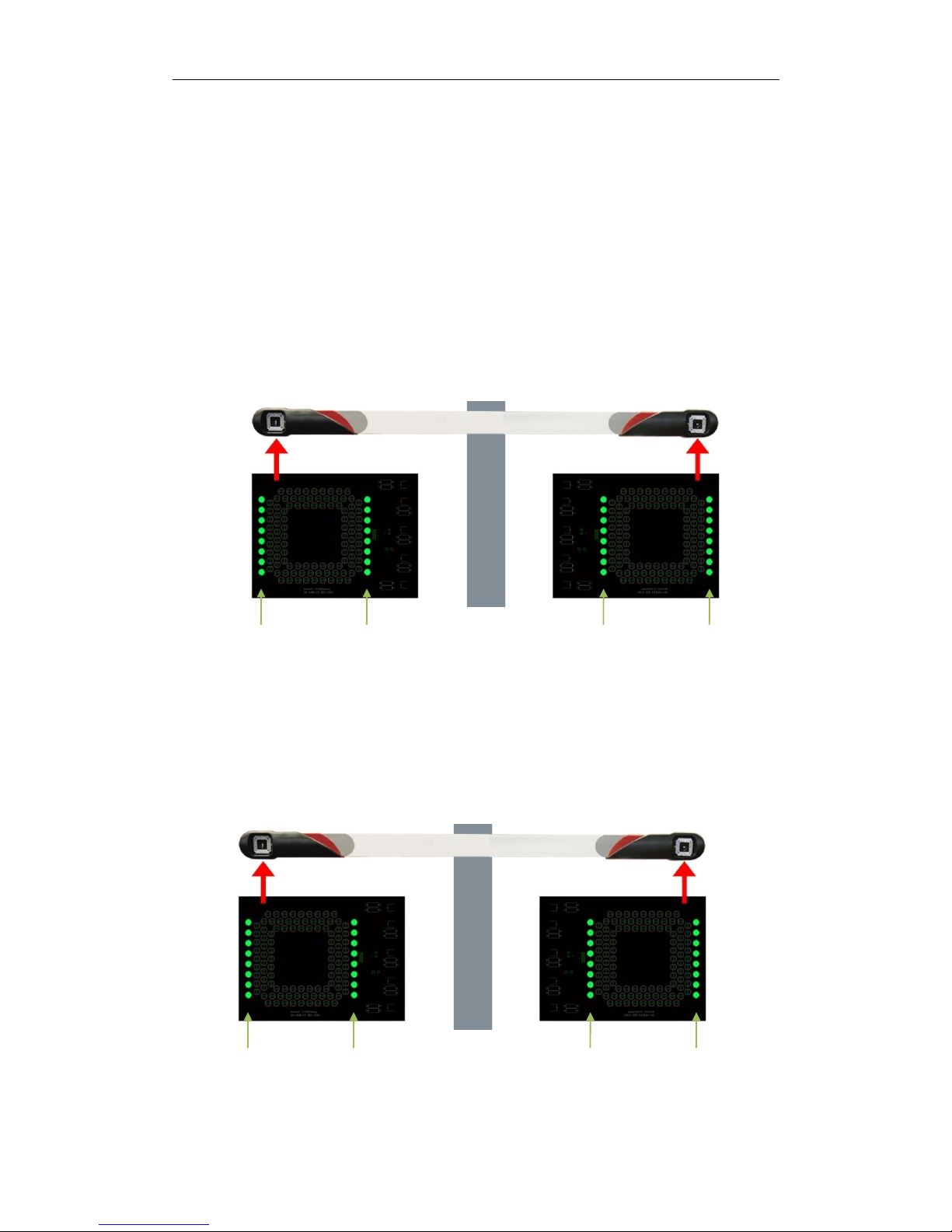
2.2 Smart LED board...................................................................................................6
2.3 Equipment and Servicing.......................................................................................8
1. Check List.........................................................................................................8
2. Camera Care....................................................................................................9
3. Target Care.......................................................................................................9
III. Installation Guide................................................................................................10
3.1 Installation Dimensions........................................................................................10
3.1.1 Camera Beam Position..............................................................................10
3.1.2 Level Lift.....................................................................................................11
3.2 Positioning............................................................................................................13
3.3 Installing wheel clamps and target.......................................................................14
3.3.1 Installing wheel clamps..............................................................................14
3.3.2 Fixing targets.............................................................................................14
3.4 Installing/Removing brake depressor..................................................................15
3.5 Installing/Removing steering wheel holder..........................................................15
IV. Software..............................................................................................................16
4.1 Opening/Closing Alignment software...................................................................16
4.2 Hot keys...............................................................................................................17
4.3 Visual Check........................................................................................................18
4.4 Standard Measurement.......................................................................................18
4.5 Quick Measurement.............................................................................................37
4.6 Aligner Management............................................................................................40
V.Technical data.............................................................................................................45
5.1 Measuring Range.................................................................................................45
5.2 Power supply unit.................................................................................................45
Appendix I . Troubleshooting.............................................................................................46
2

IDEAL 60-1500 Wheel Aligner Manual
I. Introduction
The purpose of this manual is to provide safe and practical instructions for
operation and maintenance of the imaging wheel aligner.
1.1 Warning
This aligner is designed for INDOOR SE ONLY. Exposure to damp or wet
locations can cause damage to the aligner’s components or injury to the
user and will void warranty.
The computer in this aligner is capable of connecting to a network and/or the
Internet. This functionality is only for use when receiving support for the
aligner. The computer should be connected to the Internet if possible,
however it should never be used for recreational or administrative purposes.
Any malfunctions due to unauthorized software, malware, viruses, or similar
web based threats are not
Do not plug in the cabinet power cord until all connections have
been verified. Damage or injury can result.
1.2 Safety Warning
This imaging aligner is intended for use by properly trained automotive
technicians. The safety messages presented in this section and throughout
the manual are reminders to exercise extreme care when performing wheel
alignments with this product.
There are many variations in procedure, technique, tools, and parts for
servicing vehicles. The manufacturer cannot possibly anticipate or provide
advice or safety messages to cover every situation. It is the automotive
technician’s responsibility to be knowledgeable about the vehicle to be
aligned. It is essential to use proper servicing methods. Always perform wheel
alignments in an appropriate manner, that does not endanger operator safety,
the safety of others in the work area, the equipment, or the vehicle being
serviced.
Read this manual carefully before powering up the aligner. Save this manual,
and all supplied illustrative material, in a folder near the aligner cabinet, where
it is readily accessible for reference by operators.
3

IDEAL 60-1500 Wheel Aligner Manual
The technical documentation supplied is considered an integral part of this
equipment; in the event of sale all relative documentation must remain with
the system.
This manual is only valid for the equipment model and serial number indicated
on the nameplate of the included aligner. The nameplate is attached to the
back of the cabinet.
WAR I G!
Any modifications to this aligner may cause serious injury or
damage to the aligner. The manufacturer and distributors are not
responsible for any injury caused by improper use, abuse, or unauthorized
repair.
4

IDEAL 60-1500 Wheel Aligner Manual
II. Getting Started
2.1 Equipment Transport Conditions
The aligner must be shipped in its original packing and stowed in the position
indicated on the outside.
To avoid damage, never place other items on top of the packaging.
Handling of the crated aligner must be performed only with an appropriate
lifting device such as a forklift or pallet jack.
Only personnel who are experienced and qualified in freight handling
procedures should handle any transportation or moving of the crated aligner.
Inspect for any damage to the crate and notify your local distributor (and/or
freight company) immediately if any damage is observed.
Uncrating Instructions:
Carefully remove packing materials. Be careful when cutting banding material
as items may loosen and fall, causing personal harm or injury.
Always wear gloves when uncrating to prevent scratches, abrasions, or cuts
due to the contact with packing materials.
Retain all packaging in case you need to return any parts for warranty or
servicing. Carefully unpack and inventory all items. Familiarize yourself with
all components before beginning set up and assembly.
5

IDEAL 60-1500 Wheel Aligner Manual
2.2 Smart LED Board
Smart LED board includes the following features:
Target Level Indication
LR Target LF Target RF Target RR Target
If the target is not leveled, LED lights will turn red. When all the lights turn
green and the middle two lights start to blink, the target is leveled.
Forward/Backward Moving Car Indication
Position Direction Position Direction
The left line of LED lights represents the position of the vehicle. The right line
6

IDEAL 60-1500 Wheel Aligner Manual
of LED lights shows the direction, forward or backward, of the measured
vehicle.
Swing Caster Indication
Direction Angle Direction Angle
The left line of LED lights represents the direction of turning angle, clockwise
or counterclockwise, of the measured vehicle. The right line of LEDs show the
progress of the turning angle.
Target Blocking Indication
LR Target LF Target RF Target RR Target
When the middle two lights turn red and start to blink, the corresponding
target is blocked.
7

IDEAL 60-1500 Wheel Aligner Manual
2.3 Equipment and Servicing
1. Check List
Standard Configuration:
Computer 1 Wheel Clamp 4
Post 1 Wheel Stopper 2
Monitor 1 Steering Wheel Holder 1
Cabinet 1 Brake Depressor 1
Software 1 Manual 1
Printer 1 Power Cord 1
Target 1 Set of 4
8
PS AVR 1

IDEAL 60-1500 Wheel Aligner Manual
Warning!
Please use the original accessories provided by the manufacturer.
The manufacturer and distributors are not liable for any damage or injury
caused by improper use.
2. Camera Care
Keep hand and tools away from camera.
Warning: Keep grease away from the lenses. Do not use water, detergents,
or ammonia when cleaning the lenses. Do not use heavy pressure when
cleaning. Do not use a shop rag, they may contain particles and chemicals
that can damage the lenses.
A non-ammonia cleaner may be sprayed onto a clean, lint free cloth to gently
clean the lenses. Non-ammonia glass wipes may also be used, such as Armor
All glass wipes..
Do not spray cleaners directly onto the targets.
3. Target Care
Keep targets clean, keep hands and tools away from the surface of targets.
Check that wheel clamps and targets are firmly attached and avoid dropping
the targets.
Note: When the targets are not in use detach the targets and
clamps. Store them on the cabinet. Do not put the target faces
downward onto any surface.
Warning: Do not use water, detergents, or ammonia when cleaning the
targets. Do not use heavy pressure when cleaning. Do not use a shop rag,
they may contain particles and chemicals that can damage the targets.
A non-ammonia cleaner may be sprayed onto a clean, lint free cloth to gently
clean the targets. Non-ammonia glass wipes may also be used, such as
Armor All glass wipes.
Do not spray cleaners directly onto the targets.
9

IDEAL 60-1500 Wheel Aligner Manual
III. Installation Guide
3.1 Installation Dimensions
3.1.1 Camera Beam Position >100mm (4 Inches)
Diagram: Distance between post and wall
10

IDEAL 60-1500 Wheel Aligner Manual
Diagram: Distance between cameras to center of turn table.
(See Table on page 11)
Diagram: Offset between Camera beam and turn table
L H
1800mm / 71” 550mm / 21.5”
2000mm / 78.75” 550mm / 21.5”
2200mm / 86.5” 600mm / 23.5”
2500mm / 98.5” 600mm / 23.5”
2800mm / 110.25” 600mm / 23.5”
11

IDEAL 60-1500 Wheel Aligner Manual
3.1.2 Lift Levelness
All eight measurement points need to be within 2mm (1/8”)
Diagram: Requirement for leveling lift.
12

IDEAL 60-1500 Wheel Aligner Manual
3.2 Positioning
Diagram: Positioning for fixed camera post & beam assembly.
Measure the distance between the inner sides of the runways on the lift and
find the center point. Shown as A and B. Find the center line of the lift using
these two points.
With turn table locked, at the alignment level, find the center point of the turn
table. Link the two center points of the turn table, as shown at C.
From the center line of the turn table, measure L1. Mark the first position of
the post
Mark the four point for the base of the post. Shown as E and D.
OTE:This is also the optimum positioning for mobile units.
13

IDEAL 60-1500 Wheel Aligner Manual
3.3 Installing Wheel Clamps and Target
3.3.1 Installing Wheel Clamps
Caution: Different wheels may have different clamping surfaces. Special
fingers may be required when used on specialty or high end wheels.
3.3.2 Attaching Targets
Always check that wheel clamps are firmly attached to wheels. Socket pins of
the measurement board may be lightly lubricated to protect the pin and
14

IDEAL 60-1500 Wheel Aligner Manual
socket. Mount the two small targets in the front and the two larger targets in
the rear. Keep the bubble level on top.
3.4 Installing/Removing Brake Depressor
Place a cloth underneath the depressor to protect the seat if necessary. After
run out compensation, install the brake depressor for further measurements.
3.5 Installing/Removing Steering Wheel Holder.
The steering wheel holder holds the steering wheel in position and locks the
wheels.
1. Place the steering wheel holder on the seat and press the plate against
the seat.
2. Slide the arms downwards against the seat.
3. Release the arms so that pressure is exerted on the steering wheel.
4. Remove in the reverse order.
15

IDEAL 60-1500 Wheel Aligner Manual
IV. Software
4.1 Opening/Closing Alignment Software
Switch on power supply and push the power button to start the computer. The
computer should start the alignment software automatically. In case the
alignment software does not start, click on the icon to start the
alignment software.
If you do not see a shortcut for the alignment software, please make sure your
alignment software is properly installed; contact your local service center if
necessary.
OTICE: If running this software on win8 or win10, please set to “Run as
administrator.”
4.2 Hot keys
This aligner uses an IBM standard keyboard, there are 12 function keys from
F1 to F12 located on the top of the keyboard. There are also specific function
keys located on the right side of the keyboard, such as “Page p”, “Page
Down”, “Enter” “Home” and arrow directional keys. Instructions for these
function keys will be explained in following sections.
F10 - Help Version
Pg p - Previous PgDn - Next
Home - Press HOME key under any screen to go back to
software main menu screen
Warning: Do NOT directly switch off the power supply to shut down the
computer. Switching off power directly may affect proper operation of the
Operating System.
16

IDEAL 60-1500 Wheel Aligner Manual
Diagram: Main screen
Help Previous
Next Clear Run Out
ESC –Exit Program Version Info
Management
4.3 Visual Check
Click or press F1 to enter visual check.
17

IDEAL 60-1500 Wheel Aligner Manual
Diagram: Visual Check
Defective, replacement needed.
Warning, repair needed.
Normal, no action needed.
Next: Enter next screen.
Print: Print check table or check report as desired.
4.4 Standard Measurement
After visual check,click standard measurement to enter measurement
screen. Or click or press F2.
Standard measurement: Select customer → Select vehicle manufacturer →
18

IDEAL 60-1500 Wheel Aligner Manual
Run out compensation → Caster Measurement → Rear Axle Measurement →
Live Caster Adjustment → Front Axle Measurement → Print.
1. Select Enter customer info. Click “New Customer” and enter
customer info.
Diagram: Standard Measurement- Select Customer
Diagram: Enter license plate number.
2. Select vehicle model . Select vehicle specification, Select
vehicle manufacturer, year and model.
19

IDEAL 60-1500 Wheel Aligner Manual
Diagram: Standard Measurement - Select vehicle model.
Click next to enter manufacturer spec page.
Diagram: Standard Measurement – Manufacturer Spec
3. Click next or to enter run out compensation.
During the alignment process, run out compensation is very important.
Skipping compensation will cause inaccurate alignment readings.
Before continuing, make sure both turn tables are locked and wheel stoppers
are in place.
20
Table of contents
Popular Wheel Balancer manuals by other brands

Butler
Butler LIBRAK350 instruction manual

Dannmar
Dannmar MB-240X Installation and operation manual

Fasep
Fasep VIDEOTRONIC V653.G2 user manual

HENNESSY INDUSTRIES
HENNESSY INDUSTRIES Coats 885 Safety Instructions, Set Up Instructions, Operation Instructions, Maintenance Instructions

Hofmann Megaplan
Hofmann Megaplan MS400-2 Technical maintenance manual

Hofmann
Hofmann Megaspin 420 quick start guide