Cascade Health and Fitness Raptor 702022 User manual

INSTRUCTION MANUAL
PLEASE READ THIS INSTRUCTION MANUAL
BEFORE YOU BEGIN ASSEMBLY
!
ReNegaDE
START
STOP
RESET
ENTER
WARNING:
Heartrate monitoring systems
maybe inaccurate. If you feel faint,
stopexercising immediately
Cal./hr
Meter
QuickStart
1.
Press " ENTER "
2.
Press " START "
3.
Go!
MODEL # 702022
cascadehealthandtness.com
HEALTH & FITNESS
R
Cascade Raptor Functional Trainer
VERSION: 20221026

2
contents
safety information 03
customer support 04
assembly instructions 05
cascade raptor features explained 15
computer instructions 18
- quick start
- button functions
- console display and feedback
- using workout programs
how to take care of your cascade raptor 25
troubleshooting 25
exercising with your cascade raptor 26
exploded diagrams and parts list 30
console assembly 38
your warranty 39
cascadehealthandtness.com

Safety Information
3
PLEASE READ THIS INSTRUCTION MANUAL BEFORE YOU BEGIN ASSEMBLY. GREAT
CARE HAS BEEN TAKEN TO DESIGN THESE INSTRUCTIONS AND FOLLOWING THEM
WILL HELP YOU WITH QUICKER ASSEMBLY AND MINIMIZE THE RISK OF INJURY
Safety Standards
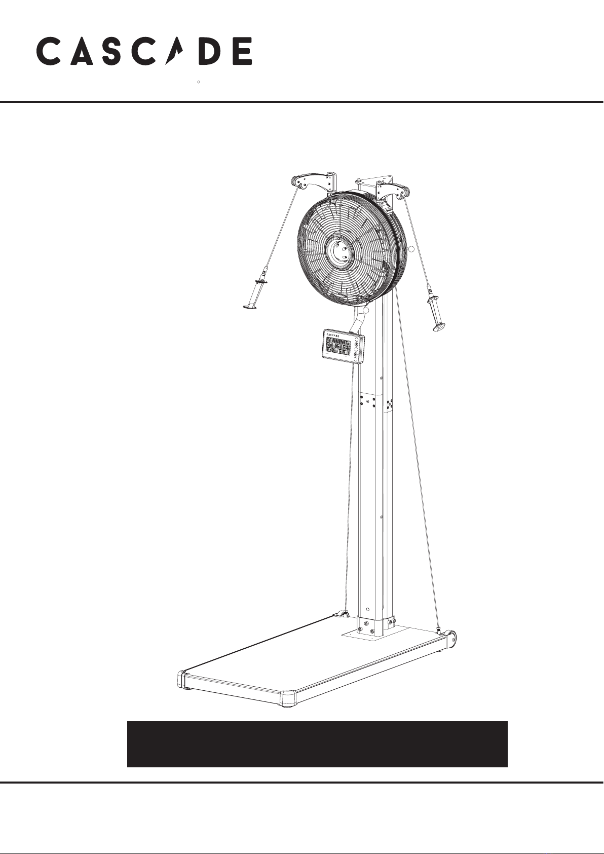
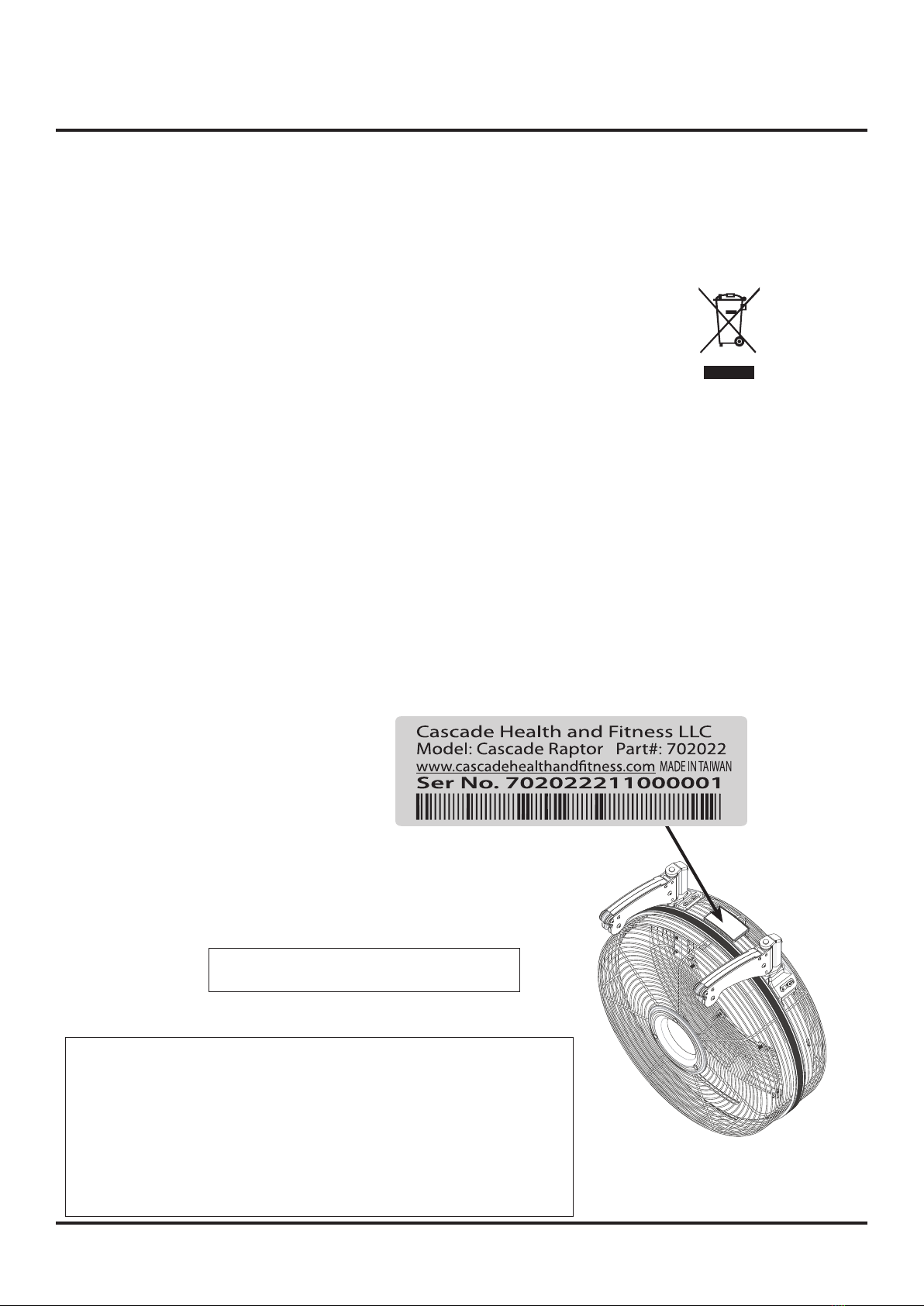
This Cascade Raptor meets the requirements of the EN ISO 20957-1: 2013, Class SA
It is important that you keep these instructions for future reference.
This product is not suitable for therapeutic purposes.
YOU ARE RESPONSIBLE FOR YOUR OWN SAFETY -
THIS LIST IS NOT EXHAUSTIVE.
•Always assemble and operate the product on a level surface,
ensure that the product is stable before use.
• Try to ensure that your back is straight while exercising,
especially for long periods
•The safety level of this equipment can only be maintained
if it is regularly examined for wear and tear
•Keep hands away from moving parts.
•Replace defective components immediately, and/or
keep the equipment out of use until it is repaired.
•Use only the adjustment settings as described in the
instructions. Always use the correct adjustment pin/xing.
•Special attention should be taken to inspect the
components, such as pulleys, bearings, straps, rollers are
always more susceptible to wear before use.
•Never leave any adjustment devices projecting from the
product.
•Always wear suitable clothing and footwear e.g. tracksuit /
shorts / training shoes
•Remove all personal jewellery before exercising.
•Ensure you warm-up well before using the equipment as
this will help to prevent muscle strain.
•After eating, allow 1-2 hours before exercising as this will
help to prevent muscle strain.
• Never overload the equipment – the maximum user weight
of this product is 180kg / 400lbs.
•Don’t rock this equipment form side to side
•Never use the equipment in any other manner other than
the ways explained in these instructions and/or any
wall-chart supplied.
•This product has an intergrated resistance system without
a constant power mode that is governed by magnetic
resistance.
•Losing grip or suddenly releasing the handle could result
in an uncontrolled return, ensure there is free space around
the product.
•You may want to store this product away to save space -
be aware of moving mechanical parts which could cause
injury.
•To prevent shock, keep all electical components, such as
the console, motor, cord and switch away from water.
•Do not use any accessories that aren’t specically
recommended by the manufacturer, these might cause
injuries or cause the unit to fail.
•Work within your recommended exercise level, do NOT
work to exhaustion.
•If you feel any pain or abnormal symptoms, STOP YOUR
WORKOUT IMMEDIATELY. Consult your physician
immediately.
•Parents and others in charge of children should be aware
of their responsibility, because the natural play instinct
and the fondness of experimenting of children can lead to
situations and behaviour for which the training equipment
is not intended
•If children are allowed to use the equipment,
their mental and physical development and above all
their temperament should be taken into account. They
should be controlled and instructed in the correct use
of the equipment.
•The equipment is under no circumstances
suitable as a children’s toy.
•This appliance is not intended for use by persons
(including children) with reduced physical, sensory or
mental capabilities, or lack of experience and knowledge,
unless they have been given supervision or instruction
concerning use of the appliance by a person responsible
for their safety.
• The free area shall be not less than 2’ greater than
the training area in the directions from which the
equipment is accessed.
Injuries to health may result from incorrect or excessive training.
!
Heart Rate Monitoring System may be inaccurate, Over exercise may result in
serious injury or death. If you feel faint stop exercising immediately !
Be aware of the edges on the platform when in use or move it around.
!
!
!
The safety maximum length of the pulling handle motion on this product is 79”,
please be aware to avoid any exercise that is over this motion range limit.
It is your responsibility to contact us for further advice, when you found any damages which
impact the original design and potential issue caused on the product after carton opened.
!
!
The max. operating force allowed is 39 lbs.
!
cascadehealthandtness.com
HEALTH & FITNESS
R

Customer Support
Should you require any assistance regarding this product please gather the following information,
and then contact us using the details below:
1. Serial no. - this can be found on
the sticker below, located as indicated.
For future reference, please write down
your serial number in the space
provided below.
2. Original purchase date
3. Place of purchase
4. Information about the place
and conditions of use
5. Precise description of the issue/defect
Your Serial No. is:
Care & Maintenance
•
Always place the equipment in a dry environment.
•
Use a warm, damp cloth to keep the product clean.
•
Do not use liquids to clean the electrical components and make sure to unplug before any care/maintenance.
•
The safety level of the equipment can be maintained only if it is regularly examined for damage and wear. This
includes any straps, pulleys, nuts, bolts, moving parts, bushes, cords, wheels, bearings & connection points etc
•
Ensure that you inspect the product regularly - at least once a week is recommended.
•
Ensure that all xings are tight before use.
•
Always replace damaged / worn components with original parts from the manufacturer.
Protect the environment by not disposing of this product with household waste.
Check your local authority for recycling advice and facilities (Europe only).
•
This appliance is not intended for use by persons (including children) with reduced physical, sensory or mental
capabilities, or lack of experience and knowledge, unless they have been given supervision or instruction
concerning use of the appliance by a person responsible for their safety.
•
Children should be supervised to ensure that they do not play with the appliance.
•Non-rechargeable batteries are not to be recharged.
•Rechargeable batteries are to be removed from the appliance before being charged.
•Dierent types of batteries or new and used batteries are not to be mixed.
•Batteries are to be inserted with the correct poiarity.
•Exhausted batteries are to be removed form the appliance and safely disposed of
•If the appliance is to be stored unused for a long period, the batteries should be removed.
•The supply terminals are not to be short-circuited.
Contact Us
4
info@cascadehealthandfitness.com
p 425-402-4062
cascadehealthandtness.com

Assembly Instruction
If you suspect you may have some parts missing, please
contact us before going back to your retailer. Refer to the
Customer Support section on page 4 for contact details.
!
This Cascade Raptor takes up
a oor space of 40” x 24” for use,
and weighs 185 lbs.
!
Before you start
1. Prepare your work area -
It is important for you to
assemble the product at
a clean and uncluttered
space.
2. Work with a friend -
we recommend you
to have someone
assisting you with the
assembly as some of the
components are quite
heavy.
3. Open the carton -
checking any warnings
on the carton and make
sure you have it the
right way up.
4. Unpack the carton
Make sure you have
the following parts:
Tools and Consumables
5
Allen Key (6mm and 5mm)
Part
No.
Q1
Console
x 1
Part
No.
M18
Pulling Grip
Handle Bar
x 2
Part
No.
M42
702022
Main Body
Cross Grip
Handle bar
x 2
Fixings
Part
No.
S7
M8 x 25mm
Hex Socket
Head Bolt
x 4
(For bracket attachment used)
Part
No.
Q8
M6 x 10mm
Allen Head Bolt x 2
(Pre-attached on console post)
AA Batteries
x 4
cascadehealthandtness.com
HEALTH & FITNESS
R
Part
No.
M49
Universal Adaptor
x 1
Part
No.
M50
Carabiner
x 1

If you suspect you may have some parts missing, please
contact us before going back to your retailer. Refer to the
Customer Support section on page 4 for contact details.
!
This Cascade Raptor takes up
a oor space of 40” x 24” for use,
and weighs 185 lbs.
!
Tools and Consumables
Part
No.
E1
Cable Wire
Assembly
x 2
Part
No.
C1
Part
No.
C2
Platform
Part
No.
F
Fixings
Part
No.
S3
M8 x 30mm
Hex Socket
Head Bolt
x 4
Part
No.
B1
Part
No.
D1
Bottom Section
Rear Upright Post
x 1
Part
No.
D2
Top Section
Rear Upright Post
x 1
Part
No.
D5
Top Fixing Plate
x 1
Part
No.
A3
Part
No.
S1
M10 x 65mm
Hex Socket
Head Bolt
x 3
Part
No.
S2
M10 x 55mm
Hex Socket
Head Bolt
x 2
Part
No.
B2
Plastic Pulley
Roller
x 4
Part
No.
B3
M10 x 40mm
Hex Socket
Head Bolt
x 2
Part
No.
B4
Metal Spacer
x 2
Bottom Section
Main Stem
x 1
Top Section
Main Stem
x 1
Elastic Cord
x 1
Right Lock Handle
- 128mm
x 1
Part
No.
E2
Metal Spring
Spacer
x 2
Part
No.
S6
8 x 16 x 2mm
Washer x 4
Part
No.
S8
M10 Hex Head
Locknut x 5
Allen Key (8mm, 6mm and 5mm)
Wrench (13/17mm )
Part
No.
A28
Left Lock Handle
- 92mm
x 1
6cascadehealthandtness.com

1. Attach the Main Stem Assembly
1-1 Attach the Bottom Section Main Stem
• Attach the Bottom Section Main Stem (C1) to the mounting
bracket carefully with three M10 x 65mm Hex Socket Head
Bolts (S1) & M10 Hex Head Locknuts (S8) with nger tight in
position rstly.
FIXINGS:FIXINGS:
x 3
FIXINGS:TOOLS:
8mm
Bottom
Section
Main
Stem
Mounting
Bracket
Platform
1-2 Attach the bottom Pulley Rollers
• Attach two Plastic Pulley Rollers (B2) & Metal Spacer (B3)
onto the back of the Bottom Section Main Stem (C1) with
M10 x 40mm Hex Socket Head Bolt (B4) in the same order
as the diagram shown.
• Tighten the bolt securely with the 8mm Allen Key - provided.
Bottom
Section
Main
Stem
Pulley
Rollers
Metal
Spacer
FIXINGS:FIXINGS:
x 2
FIXINGS:TOOLS:
8mm
x 1
x 1
x 3
Part
No.
S1
Part
No.
S8
Part
No.
B2
Part
No.
B3
Part
No.
B4
7
#13/17
cascadehealthandtness.com
HEALTH & FITNESS
R

FIXINGS:FIXINGS:
x 2
FIXINGS:TOOLS:
8mm
x 1
x 1
1-3 Attach the top Pulley Rollers
• Attach two Plastic Pulley Rollers (B2) & Metal Spacer (B3)
onto the back of the Top Section Main Stem (C2) with
M10 x 40mm Hex Socket Head Bolt (B4) in the same order
as the diagram shown.
• Tighten the bolt securely with the 8mm Allen Key - provided.
1-4 Attach the Top Section Main Stem
• Loosen four M10 x 35mm Socket Set
Screws (C8) attached on the Bottom
Section Main Stem 3 ~ 4 threads with
provided 5 mm Allen Key carefully.
• Loosen four M10 x 35mm Socket Set
Screws (C8) attached on the Top Section
Main Stem 3 ~ 4 threads with provided
5 mm Allen Key carefully.
• Attach the Top Section Main Stem (C2) to
the Bottom Section Main Stem (C1) even-
ly and tighten the M10 x 35mm Socket Set
Screws (C8) on both section main stems
securely with the 5 mm Allen Key –
provided.
Top
Section
Main
Stem
Pulley
Rollers
Metal
Spacer
Make sure the bolts are fully tightened
evenly with the allen key.
!
1-5 Attach the Lock Handles
• Attach Right Lock Handle (A3) onto the
Rear Carriage Assembly and secure by
clockwise tighten as the diagram shown.
• Attach Left Lock Handle (A28) onto the
Rear Carriage Assembly and secure by
clockwise tighten as the diagram shown.
Bottom
Section
Main
Stem
Top
Section
Main
Stem
M10 x 35mm
Socket Set
Screw
Right
Lock
Handle - 128mm
Left
Lock
Handle-92mm
Rear
Carriage
Assembly
FIXINGS:FIXINGS:
x 8
FIXINGS:TOOLS:
5mm
Part
No.
B2
Part
No.
B3
Part
No.
B4
Part
No.
C8
8cascadehealthandtness.com

2. Attach the Rear Upright Post Assembly
FIXINGS:FIXINGS:
x 4
FIXINGS:TOOLS:
2-2. Attach the Top Section Rear Upright Post
• Loosen four M10 x 25mm Socket Set Screws (D4)
attached on the Bottom Section Rear Upright Post 3 ~ 4
threads with provided 5 mm Allen Key carefully.
• Loosen four M10 x 25mm Socket Set Screws (D4)
attached on the Top Section Rear Upright Post 3 ~ 4
threads with provided 5 mm Allen Key carefully.
• Attach the Top Section Rear Upright Post (D2) to the
Bottom Section Rear Upright Post (D1) evenly and
tighten the M10 x 25mm Socket Set Screws (D4) on
both section rear upright posts securely with the 5 mm
Allen Key – provided.
M10 x 25mm
Socket Set Screw
2-1 Attach the Bottom Section Rear Upright Post.
• Attach the Bottom Section Rear Upright Post (D1) to the
mounting bracket carefully with two M10 x 55mm Hex
Socket Head Bolts (S2) & M10 Hex Head Locknuts (S8)
with nger tight in position rstly.
FIXINGS:FIXINGS:
x 2
FIXINGS:TOOLS:
Bottom
Section
Rear
Upright
Post
Rear
Mounting
Bracket
Bottom Section Rear
Upright Post
Top
Section
Rear
Upright
Post
Make sure the bolts are fully tightened
evenly with the allen key.
!
8mm
x 2
5mm
Part
No.
S2
Part
No.
S8
Part
No.
D4
9
#13/17
cascadehealthandtness.com
HEALTH & FITNESS
R

3. Attach the Side Cable Wires Assembly
3-2 Attach the Side Cable Wires
• Pull the Cable Wire (E1) straight and thread the M10 x
16mm Cable Wire Bolt to the Metal Sleeve (F8) on
the front edge of Standing Platform (F1) as shown
• Repeat the same procedures for the other Cable Wire
Attachment.
• Tighten the bolts evenly to keep the Main Stem &
Rear Upright Post straight and securely with the
#13/17 Wrench – provided.
3-1 Attach the Top Fixing Plate
• Slide the Cable Wire Ball End (E1) through the xing hole on the
Top Fixing Plate (D5) and insert the Metal Spring Spacer (E2)
onto the cable wire and engage it into the xing hole securely
as diagram shown carefully.
• Pull the Cable Wire downward to locate the Cable Ball End with
Metal Spring Spacer in position properly.
• Repeat the same procedures for the other Cable Wire attachment.
• Attach the Top Fixing Plate (D5) to the Top Section Main Stem
(C2) and Top Section Rear Upright Post (D2) evenly with four M8
x 30mm Hex Socket Head Bolts (S3) and 8mm x 16mm x 2 mm
Washers (S6) in the same order as the diagram shown.
• Tighten the bolts securely with the 6mm Allen Key - provided.
Metal
Spring
Spacer
Cable Wire
Ball End
Top Fixing
Plate
Metal
Sleeve
Cable Wire
Main
Stem
Cable Wire
Bolt
Top Fixing
Plate
M8 x 30mm
Socket Head Screw
8 x 16mm
Washer
FIXINGS:FIXINGS:
x 4
FIXINGS:TOOLS:
8mm
x 4
Try to feel the tension of two
cable wires to ensure IF they
are tightened.
!
Ensure that the threads
are engaged to a depth
of 4 / 5 Cable Wire Bolt
threads at least.
!
3-3 Tighten all of the bolts & screws securely
• Tighten three M10 x 65mm Hex Socket Head Bolts (S1) &
M10 Hex Head Locknuts (S8) on the Main Stem Mounting
Bracket securely with 8mm Allen Key & 13/ 17 Wrench.
• Tighten two M10 x 55mm Hex Socket Head Bolts (S2) & M10
Hex Head Locknuts (S8) on the Rear Upright Post Mounting
Bracket securely with 8mm Allen Key & 13/ 17 Wrench.
Make sure the bolts are fully tightened with the allen key & wrench.
!
2
3
1
#13/17
Part
No.
S3
Part
No.
S6
10 cascadehealthandtness.com

4. Attach the Console
All of the required bolts & washers had been pre-assembled to ensure its installation quality,
remove the relative bolts & washers then fasten as instructions
to complete your Cascade Raptor assembly.
!
4-2 Power Up
• Install the AA battery x 4 provided into the compartment
in the back of the console properly
• Attach the battery cover onto the console securely.
4-1 Attach the Console Arm
• Remove the two M6 x 10mm Allen Head Bolts (Q8)
from the Console Mounting Tube with the 4mm Allen Key provided as shown.
FIXINGS:FIXINGS:
x 2
FIXINGS:TOOLS:
5mm
• Connect the Console Section Wires ( 3 pins plug & 3 pins socket ) (Q9) and
Middle Section Wires ( 3 pins socket & 3 pins plug ) (Q10) & (Q11) together accord-
ingly and then insert these two wires into the Console Arm (Q6) carefully.
• Attach the Console Arm (Q6) to the mounting tube carefully with two M6x 10mm
Allen Head Bolts (Q8) with nger tight in position rstly and then secure with the
4mm Allen Key – provided.
Part
No.
Q8
11
cascadehealthandtness.com
HEALTH & FITNESS
R
Console
Mounting
Tube
Console
Arm
Middle
Section
Wires
Console
Section
Wires
1.
2.
Console
Mounting Tube

5. Attach the Grip Handles
• Use your thumb & index nger of one hand to grasp
& pull the locking sleeve as shown.
• Attach the plug head of selected handle into the
locking socket and release to secure the handle at-
tachment properly.
• Repeat the other side handle with same procedures.
6. Attach the Main Body FIXINGS:FIXINGS:
x 4
FIXINGS:TOOLS:
6-1. Remove the metal posts from the back of the main body
• Loosen the four M8 x 60mm Hex Socket Head Bolts
from the two metal posts as shown.
Note: The four Hex Socket Head Bolts,
four Plastic Spacers and the two
Metal Posts are used for packaging
protection purpose, which won’t be
used again during the assembly.
Locking
Sleeve
Plug Head
Plastic
Spacers
Metal
Posts
M8 x 60mm Hex
Socket Head Bolt
1
2
12 cascadehealthandtness.com

Be sure to t the parts in the
same order as the diagrams
shown.
!
Make sure the bolts are fully
tightened with the allen key.
!
FIXINGS:FIXINGS:
x 4
FIXINGS:TOOLS:
Part
No.
S7
6-2. Attach the Main Body
• Have someone to assist you to hold the main body
evenly and attach it to the Fixing Bracket of the
selected attachment with four M8 X 25mm Hex Head
Socket Bolts (S7) as shown.
• Tighten the bolts securely with the 6mm Allen Key -
provided.
Fixing
Bracket
13
cascadehealthandtness.com
HEALTH & FITNESS
R

Final Checks
Your Cascade Raptor is now assembled. Please make the following checks before you use it for the rst time.
•Make sure all screws, bolts & nuts are tightened securely.
•Make sure you have positioned it on at & level surface.
7. Attach the Elastic Cord Assembly
1. Attach one End Metal Hook of the Elastic Cord (B1) to the
Fixing Hook welded on the Rear Carriage Assembly properly.
2. Wrap the Elastic Cord over the inner Top Pulley Roller and
route the Elastic Cord as diagrams shown.
3. Wrap the Elastic Cord over the inner Bottom Pulley Roller
and route the Elastic Cord as diagrams shown.
4. Wrap the Elastic Cord over the outer Top Pulley Roller and
route the Elastic Cord as diagrams shown.
5. Wrap the Elastic Cord over the outer Bottom Pulley Roller
and route the Elastic Cord as diagrams shown.
6. Attach the End Metal Hook of the Elastic Cord to the Fixing
Hook welded on the Top Fixing Plate (D5) properly as shown.
Use one hand ( left ) to stretch and hold
the Elastic Cord rstly and use the other
hand to pull the rest Elastic Cord to
reach the hook on the Top Fixing Plate.
!
6
5
Outer Top
Pulley Roller
2.
7
8
Outer Bottom
Pulley Roller
3.
9
10
Metal
Hook
Top Fixing
Plate
4.
1
2
3
Inner Top
Pulley Roller
Inner Bottom
Pulley Roller
Fixing Hook
The Elastic Cord has strong tension
after complete assembly - Take Care
while assembling!!
!
14 cascadehealthandtness.com

Cascade Raptor Features Explained
Adjusting the Console
1. Adjust the console display to suitable angle for easy
viewing by rotating the console itself with both
hands evenly as shown.
2. You can also change the console up side down for easy viewing when needed by rotating the console with both
hands evenly as shown .
• Fold down or upward the displayed screen slowly.
• Rotate the console clockwise ( or counter-clockwise ) carefully.
• Fold up or downward the displayed screen slowly as required.
Exchanging the Grip Handle
1. Use your thumb & index nger of one hand to grasp &
pull the locking sleeve as shown.
2. Attach the plug head of selected handle into the locking socket
and release to secure the handle attachment properly.
3. Repeat the other side handle with same procedures
15
Locking
Sleeve
Plug Head
1
23
cascadehealthandtness.com
HEALTH & FITNESS
R

Adjusting the Locations
1. Push to lift the Cascade Raptor slightly with both hands to remove the lock pin in position
2. Pull the right side lock handle with your right hand
and adjust the Cascade Raptor up or down on the track as wished.
3. Release the right side lock handle after the required position found.
Make sure unit is securely locked in place.
Adjusting the Resistance
1. This Cascade Raptor features a speed independent
( 14 levels adjustable ) system.
2. The harder you pull, the more resistance you will feel.
As you put more eorts into your pulling, you will go
faster, produce more watts and burn more calories.
3. The resistance is controlled by a magnet mechanism,
which is moved closer or further away from the air fan
wheel assembly – the closer the magnet is to the fan
wheel the harder the resistance.
4. The magnet is controlled manually, by moving the dial
lever.
5. The resistance levels goes from 1 = easy to 14 = hard.
16
Dial
Lever
2
3
Right Side
Lock Handle
cascadehealthandtness.com
PULL FORWARD
TO
LOWER
OR
RAISE

Levelling your Cascade Raptor
1. To help you level the Cascade Raptor on uneven surface,
there are two height adjusters attached on the rear corners
of the platform.
2. Simply turn the adjustable bolt with 5mm Allen Key –
provided to adjust the height of your Cascade Raptor
as required.
Transporting your Cascade Raptor
1. Your Cascade Raptor has 2 transport wheels on the front end
of the platform.
2. Stand yourself behind the Cascade Raptor comfortably
and hold the rear upright post with hands rmly.
3. Use your foot to stop the front end of platform while
pulling down the rear upright post to raise the platform
and then push to move it around.
17
Allen Key
(5mm)
23
1
Height Adjusters
cascadehealthandtness.com
HEALTH & FITNESS
R
Rotating the Cascade Raptor ( 702022 models )
1. Upside down –
- Pull the left side lock handle with your left hand
and rotate the Cascade Raptor clockwise carefully
until the stop pin engaged in position securely.
Left
Side
Lock
Handle
2
1
2. Back to Standard –
- Pull the left side lock handle with your left hand
and rotate the Cascade Raptor counter-clockwise
carefully until the stop pin engaged in position securely.
Left
Side
Lock
Handle
2
1
PULL
FORWARD
TO
ROTATE

Computer Instructions
Quick Start
Use this mode if you just want a quick workout session and are not interested in setting up any personal data.
•Pull for a few seconds to power the console on.
•Press the “ START “ button.
•The values of WAT TS,CALORIES,TIME,TIME/ 500M,DISTANCE,STROKES,S/M,HEART RATE
( if heart rate signal is detected ) will start displaying.
•The values of WAT TS,CALORIES,TIME,DISTANCE,STROKES will start counting upwards.
To nish this quick workout session and view your workout summary –
•Stop pulling.
•Press “ STOP “ button.
•The values of WAT TS,CALORIES,TIME,TIME/ 500M,DISTANCE,STROKES,S/M,HEART RATE
( if heart rate signal is detected ) will be displayed.
Button Functions
RESET
•Press the “ RESET”button, during the program setting mode, to
return to “START” mode on display.
•Press the “RESET” button, in “STOP” / “ PAUSE “ mode , to reset
all of the values on display to zero and return to “ START” mode.
START/STOP
•To begin a workout or restart a paused program
•To nish or pause a workout.
•To select the pre-set programs of TIME, DISTANCE, CALORIES,
STROKES, S/M, INT 20 /10, INT 20/30 & INT CUST in the “
START “ mode.
•To increase values when setting the target of the program.
Press and hold for rapid value change.
ENTER
•To conrm the target settings / program selection.
•To select the pre-set programs of INT CUST, INT 20/30,
INT 20 /10, S/M, STROKES, CALORIES, DISTANCE & TIME
in the “ START “ mode.
•To decrease values when setting the target of the
program. Press and hold for rapid value change.
“ If you stop pulling without pressing the “STOP”button, after 5 seconds the program will automatically pause. You can resume
the program by pulling again. After 1 minute of inactivity the program will end. “
“ You can change the resistance at any point during the workout by dial lever as wished. “
18 cascadehealthandtness.com

Console Display and Feedback
•Indicates the current program
text message for reference.
•Indicates the current energy (power)
generated this session, (for comparison
only, not to be used for medical purpose)
default counts up from zero to 999.
•Indicates the current heart rate in beats per
minute (bpm), which are detected by a wireless
heart rate chest strap, displayed 30 ~ 220 bpm.
NOTE : To get your pulse reading throughout the
exercise, which it gets from you by a
5.4 kHz Polar Telemetry Chest Strap.
Heart Rate monitoring system may be
inaccurate, Over exercise may result in
serious injury or death. If you feel faint stop
exercising immediately !
!
Cal./hr
•Indicates the time exercised
this session, default counts
up from 00:00 to 99:59 , but
counts down if a target had
been set (05:00 ~ 99:00).
•Indicates the approximate calories
burned this session, (for comparison
only, not to be used for medical purpose)
default counts up from zero to 9999 cal,
but counts down if a target had been set
(10 ~ 990).
•Indicates the time that is needed to achieve
500 meters distance travelled, which is
automatically calculated, default counts up
from 00:00 to 9:59.
•Indicates the distance
travelled this session,
default counts up from
0 to 99999 meter , but
counts down if a target
had been set
(100 ~ 9900 ).
•Indicates the resistance level
loaded this session, 1= easy
and 14= hard.
•Indicates the cycles
exercised this session,
default counts up from
0 to 9999 , but counts
down if a target had
been set (10 ~ 990).
•Indicates the current Stroke Per
Minute you are pulling at , default
counts up from 0 to 99 , but counts
down if a target had been set
(10 ~ 99).
•This S / M readout is automatically
calculated and displayed when
your pull is in use and should be
used as a guide to pace in workout.
Meter
19
cascadehealthandtness.com
HEALTH & FITNESS
R

Meter
TARGET Programs
This console features 5 target programs : Target TIME, Target DIS-
TANCE, Target CALORIES, Target STROKES & Target S/M.
When you reach your target the console will sound a short alarm and
end the workout by coming a stop.
Please input your Personal Data before any TARGET Programs
selected.
1. Pull the handle for a few seconds or press any buttons to activate
the console.
2. Use the “ / “ buttons to input user’s weight.
3. Press “ ENTER”to conrm your setting.
4. Use the “ / “ buttons to input user’s gender.
5. Press “ ENTER”to conrm your setting.
6. Use the “ / “ buttons to input user’s age.
7. Press “ ENTER”to conrm your setting.
Target TIME
1. Make sure the console is switched on.
“SELECT PROGRAM OR QUICK START ” scrolled on the top
segment display.
2. Use the “ / “ buttons to select the program mode you want.
“TIME” ashed on the top segment display.
3. Press “ ENTER” to conrm your selection.
4. The default value of “ 20:00 “ is ashed in the TIME window.
5. Use the “ / “ buttons to set your workout time
( 5:00 ~ 99:00 minutes).
6. Press “ ENTER”to conrm your setting.
“START” is shown on the top segment display.
7. Press “ START” to begin the workout and then start pulling.
The program will not start until you begin pulling.
NOTE : You can press ”STOP”button to end the program at any time.
The workout summary will displayed on the screen.
NOTE : You can change the resistance level ( 1~ 14 ) at any point
during the workout by dial lever as wished and relatively
readouts on display will be adjusted accordingly.
Target DISTANCE
1. Make sure the console is switched on.
“SELECT PROGRAM OR QUICK START ” scrolled on the top
segment display.
2. Use the “ / “ buttons to select the program mode you want.
“METERS” ashed on the top segment display.
3. Press “ ENTER”to conrm your selection.
4. The default value of “ 1000 “ is ashed in the DISTANCE window.
5. Use the “ / “ buttons to set your target distance
( 100 ~ 9900 meters).
6. Press “ ENTER”to conrm your setting.
“START” is shown on the top segment display.
Using Workout Programs
Meter
20 cascadehealthandtness.com
Table of contents
Other Cascade Health and Fitness Fitness Equipment manuals
Popular Fitness Equipment manuals by other brands

Creative Play
Creative Play CH141 Assembly and installation instructions

Barbarian line
Barbarian line POWER-CAGE Construction manual

SpineGym
SpineGym core exerciser Instructions for use and safety

TOORX
TOORX WBX300 Instruction

Nautilus
Nautilus 19-4944 Service manual

GymnaUniphy
GymnaUniphy Myo 200 user manual