manuals.online logo
Brands
  1. Home
  2. •
  3. Brands
  4. •
  5. Lennox
  6. •
  7. Industrial Equipment
  8. •
  9. Lennox G26 Series User manual

Lennox G26 Series User manual

11/00
*2P1100*
504,228M
*P504228M*
Page 1
E 2000 Lennox Industries Inc.
Dallas, Texas, U A
IN TALLATION
IN TRUCTION
G26 SERIES UNITS
GAS UNITS
504,228M
11/2000
upersedes 503,885M
Table of Contents
Unit Dimensions 2. . . . . . . . . . . . . . . . . . . . . . . . . . . . . . .
G26 Parts Identification 3. . . . . . . . . . . . . . . . . . . . . . . . .
Requirements 4. . . . . . . . . . . . . . . . . . . . . . . . . . . . . . . . . .
General 4. . . . . . . . . . . . . . . . . . . . . . . . . . . . . . . . . . . . . . .
Installation - etting Equipment 5. . . . . . . . . . . . . . . . . .
Return Air Opening Guidelines 5. . . . . . . . . . . . . . . . . . .
Filters & Optional Filter Assembly 6. . . . . . . . . . . . . . . .
Duct ystem 7. . . . . . . . . . . . . . . . . . . . . . . . . . . . . . . . . . .
Pipe & Fittings pecifications 7. . . . . . . . . . . . . . . . . . . .
Vent Piping Guidelines 8. . . . . . . . . . . . . . . . . . . . . . . . . .
Joint Cementing Procedure 8. . . . . . . . . . . . . . . . . . . . . .
Venting Practices 9. . . . . . . . . . . . . . . . . . . . . . . . . . . . . . .
Gas Piping 15. . . . . . . . . . . . . . . . . . . . . . . . . . . . . . . . . . .
Electrical 16. . . . . . . . . . . . . . . . . . . . . . . . . . . . . . . . . . . . .
Unit tart-Up 20. . . . . . . . . . . . . . . . . . . . . . . . . . . . . . . . .
Gas Pressure Adjustment 21. . . . . . . . . . . . . . . . . . . . . .
High Altitude Information 22. . . . . . . . . . . . . . . . . . . . . . .
Other Unit Adjustments 22. . . . . . . . . . . . . . . . . . . . . . . .
ervice 23. . . . . . . . . . . . . . . . . . . . . . . . . . . . . . . . . . . . . .
Repair Parts 26. . . . . . . . . . . . . . . . . . . . . . . . . . . . . . . . . .
Troubleshooting 26. . . . . . . . . . . . . . . . . . . . . . . . . . . . . . .
tart-Up & Performance Check List 31. . . . . . . . . . . . . .
RETAIN THESE INSTRUCTIONS
FOR FUTURE REFERENCE
WHAT TO DO IF YOU SMELL GAS:
Do not sto e o use gasoline o othe
flammable vapo s and liquids in the viĆ
cinity of this o any othe appliance.
Installation and se vice must be pe -
fo med by a qualified installe , se vice
agency o the gas supplie .
DDo not t y to light any appliance.
DDo not touch any elect ical switch; do not use
any phone in you building.
DImmediately call you gas supplie f om a
neighbo 's phone. Follow the gas supplie 's
inst uctions.
DIf you cannot each you gas supplie , call the
fi e depa tment.
DExtinguish any open flames.
If the info mation in this manual is not
followed exactly, a fi e o explosion
may esult causing p ope ty damage,
pe sonal inju y o death.
WARNING
Litho U. .A.
Downloaded from ManualsNet.com search engine
Page 2
G26 Unit Dimensions - inches (mm)
AIR FLOW
SUPPLY
AIR
OPENING
4 (102)
1 1/16
(41)
A
B
E
Retu n Ai
Knockout (Bottom)
GAS PIPING
INLET
(Both Sides)
18 7/8
(479)
ELECTRICAL
INLETS
(Both Sides)
RETURN AIR
KNOCKOUT
(Eithe Side)
28 1/2
(724)
C
23 (584)
1Ć15/16 (49)
F
TOP VIEW
FRONT VIEWSIDE VIEW
1 1/16
(41)
46
(1168)
2 1/2 (64)
2
(51)
3 5/8
(92)
23
(584)
4 1/2
(114)
CONDENSATE
DRAIN
(Both Sides)
EXHAUST
AIR OUTLET
COMBUSTION
AIR INTAKE
21 3/4
(552)
7 3/8
(187)
23 3/4 (603)
25 (635)
5/8
(16)
H
G
5/8 (16)
EXTERNAL
SIDE RETURN
AIR FILTER KIT
(Eithe Side)
(Optional)
23 (584) D
Retu n Ai
Knockout (Bottom)
4 (102)
Model No
A B C D E F G H
Model No. in. mm in. mm in. mm in. mm in. mm in. mm in. mm in. mm
G26Q2-50
G26Q3Ć50
G26Q3Ć75
16Ć1/4 413 14Ć1/8 359 12 305 12 305 2Ć1/8 54 7Ć5/8 194 14 356 12Ć3/4 324
G26Q3/4Ć100
G26Q4/5-75
G26Q4/5Ć100
21Ć1/4 540 19Ć1/8 486 18 457 18 457 1Ć5/8 41 10Ć1/8 257 20 508 18Ć3/4 476
G26Q3/4-125
G26Q4/5Ć125 26Ć1/4 667 24Ć1/8 613 18 457 18 457 4Ć1/8 105 12Ć5/8 321 20 508 18Ć3/4 476
Downloaded from ManualsNet.com search engine
Page 3
G26 Pa ts A angement
G26 PARTS IDENTIFICATION
FIGURE 1
TOP CAP
CABINET
GLA FIBER GA KET
FRE H AIR
INTAKE FITTING
BURNER BOX
A EMBLY
PATCH
PLATE
PATCH PLATE WITH
BARBED FITTING
AND FLAME
ROLL-OUT WITCH
GA VALVE AND
MANIFOLD
BURNER
BOX
COVER
FLAME IGHT
GLA
DuralokPlusTM
HEAT EXCHANGER
A EMBLY
CONDEN ER COIL
CONTROL TRAN FORMER
CONTROL BOX COVER
DOOR INTERLOCK WITCH
CONTROL VOLTAGE
CIRCUIT BREAKER
WARM
HEADER
(COLLECTOR)
BOX
COLD HEADER
(COLLECTOR)
BOX
COMBU TION AIR
INDUCER
COMBU TION AIR
ORIFICE
BLOWER
ACCE
DOOR
BURNER
ACCE
PANEL
FLUE
TRAN ITION
COMBU TION AIR
PROVE
(PRE URE)
WITCH
UPPLY
AIR
BLOWER
PRIMARY LIMIT
(ALTERNATE TYLE )
FLUE COLLAR
Downloaded from ManualsNet.com search engine
Page 4
Requi ements
All G26 units are C A International certified to AN I
Z21.47 and C A 2.3 standards.
In the U A, installation of Lennox gas central furnaces must
conform with local building codes. In the absence of local
codes, units must be installed according to the current NaĆ
tional Fuel Gas Code (AN I-Z223.1) in the United tates.
The National Fuel Gas Code is available from the following
address:
American National tandards Institute, Inc.
11 West 42nd treet
New York, NY 10036
In Canada, installation must conform with current National
tandard of Canada CAN/CGA-B149.1 Installation Code
for Natural Gas Burning Appliances and Equipment" and
CAN/CGA-B149.2 Installation Code for Propane Gas
Burning Appliances and Equipment," local plumbing or
waste water codes and other applicable local codes.
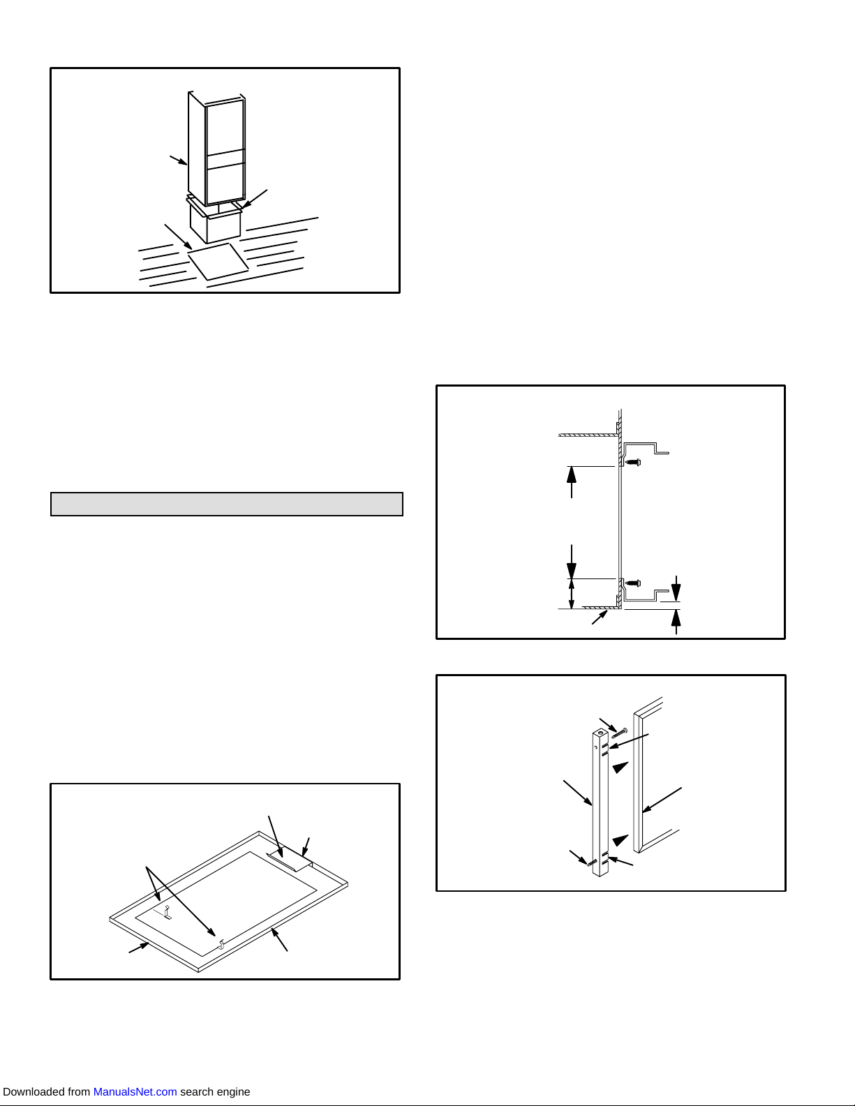
Adequate clearance must be made around the air openĆ
ings into the vestibule area. Provisions must be made for
proper operation and for combustion air and ventilation air
supply according to the current National Fuel Gas Code or
CAN/CGA-B149 standards.
This furnace is C A International certified for installation
clearances to combustible material as listed on the unit rating
plate and in table 1.
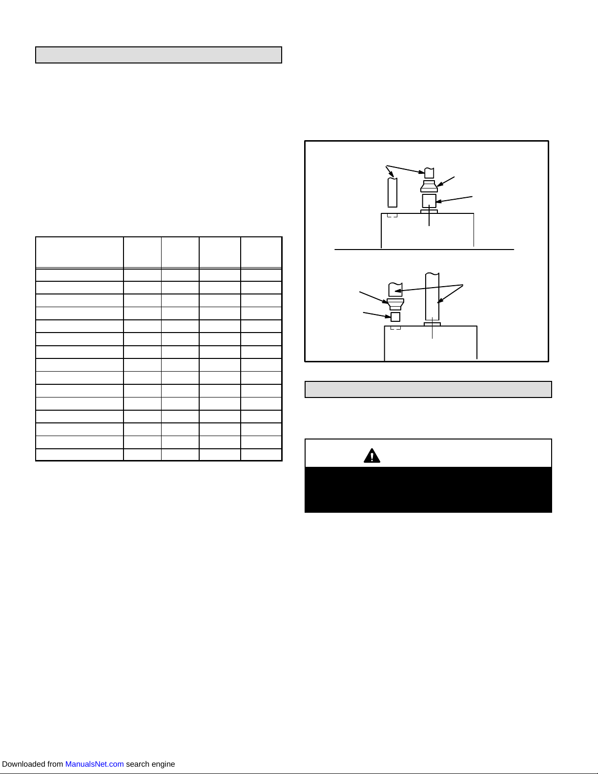
TABLE 1
Clea ances Location Inches (mm)
Front 24 (610)
ervice access Condensate side 3 (76)
(from side of unit)
Top 1 (25)
To combustible Exhaust 0
To
combustible
materials ide, rear, and front 0
Floor 0*
*Appliance shall not be installed directly on carpeting, tile or other combustible mateĆ
rial other than wood flooring.
NOTE- ervice access clearance must be maintained.
NOTE - For installation on combustible floors, the furnace shall
not be installed directly on carpeting, tile, or other combustible
material other than wood flooring.
Accessibility and service clearances must take preceĆ
dence over fire protection clearances.
For installation in a residential garage, the furnace must be
installed so that the burner(s) and the ignition source are loĆ
cated no less than 18 inches (457 mm) above the floor. The
furnace must be located or protected to avoid physical dam-
age by vehicles. When a furnace is installed in a public garage,
hangar, or other building that has a hazardous atmosphere,
the furnace must be installed according to recommended
good practice requirements and current National Fuel Gas
Code or CAN/CGA B149.1 and B149.2 standards.
The furnace must be adjusted to obtain a temperature rise
within the range specified on the unit rating plate.
When installed, the furnace must be electrically grounded
according to local codes. In addition, in the United tates,
installation must conform with the current National Electric
Code, AN I/NFPA No. 70. The National Electric Code
(AN I/NFPA No. 70) is available from the following ad-
dress:
National Fire Protection Association
1 Battery March Park
Quincy, MA 02269
Wiring to be done in the field, between the furnace and deĆ
vices not attached to the furnace or between separate deĆ
vices which are field-installed and located, shall conform
with the temperature limitation for type T wire [63°F (17°C)
rise] when installed in accordance with these instructions.
G26 unit must be installed so that electrical components
are protected from water.
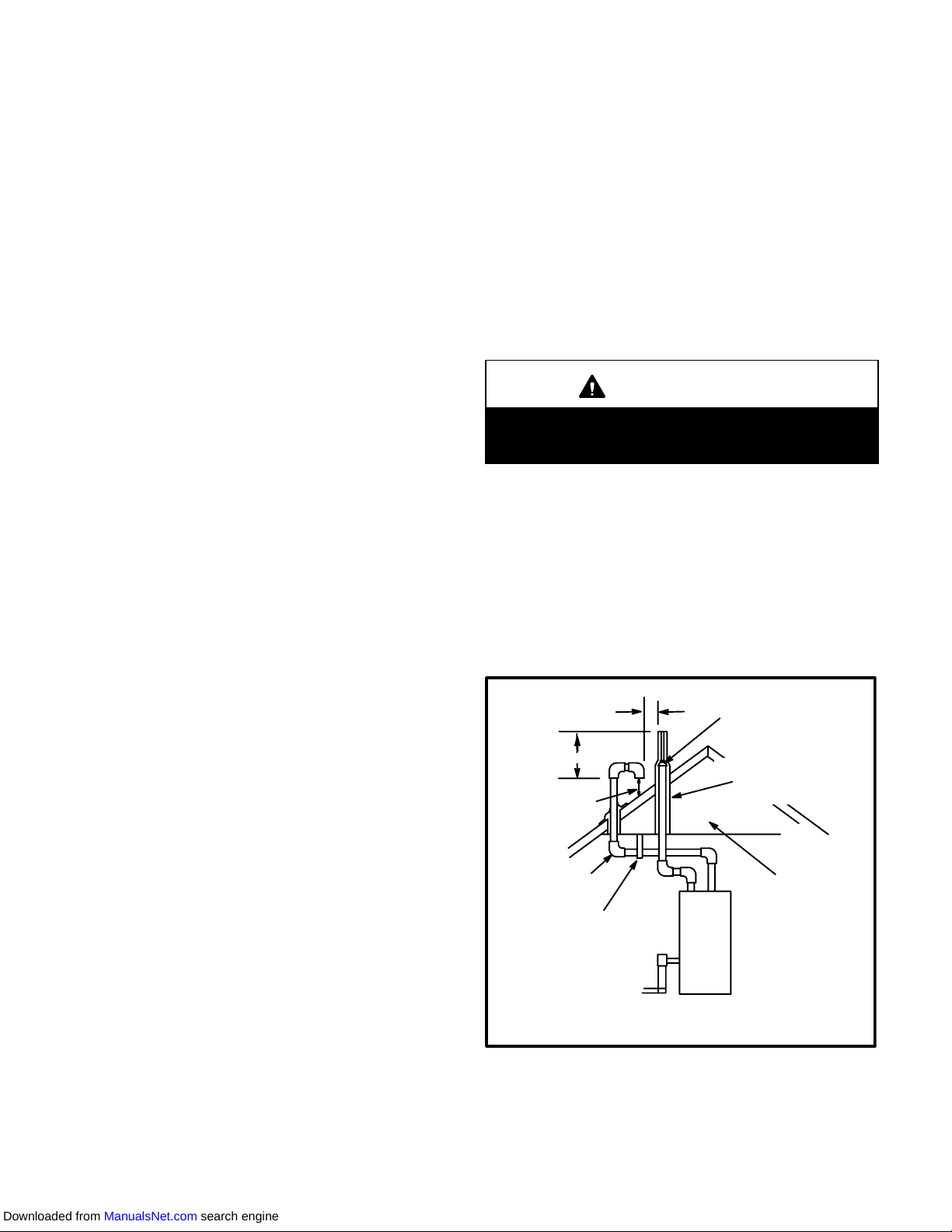
When the furnace is installed so that supply ducts carry air
circulated by the furnace to areas outside of the space conĆ
taining the furnace, return air shall be handled by a duct(s)
sealed to the furnace casing and terminating out-side
space containing furnace.
WARNING
P oduct contains fibe glass wool.
Distu bing the insulation in this p oduct du ing
installation, maintenance, o epai will expose you
to fibe glass wool dust. B eathing this may cause
lung cance . (Fibe glass wool is known to the State
of Califo nia to cause cance .)
Fibe glass wool may also cause espi ato y, skin,
and eye i itation.
To educe exposu e to this substance o fo fu the
info mation, consult mate ial safety data sheets
available f om add ess shown below, o contact you
supe viso .
Lennox Indust ies Inc.
P.O. Box 799900
Dallas, TX 75379-9900
NOTE - G26 series units must not be used as a construcĆ
tion heater during any phase of construction. Very low re-
turn air temperatures, harmful vapors and misplacement of
the filters will damage the unit and lower its efficiency.
Gene al
These instructions are intended as a general guide and do not
supersede local codes in any way. Consult authorities having
jurisdiction before installation.
Downloaded from ManualsNet.com search engine
Page 5
Shipping and Packing List
1 - Assembled G26 furnace
1 - Bag assembly containing
1 - Electrical make-up box
1 - Wiring harness
1 - nap bushing
2 - Filter clips
1 - 3 inch x 2 inch vent transition piece (-100, -125 units
only)
1 - Adapter
1 - Condensate plug
1 - Nipple
1 - Brown accessory wire
1 - Green ground wire
3 - Wire nuts
2 - tar washers
Shipping Damage
Check equipment for shipping damage. If you find any
damage, immediately contact the last carrier.
WARNING
Imp ope installation, adjustment, alte ation, se vice
o maintenance can cause p ope ty damage, pe sonĆ
al inju y o loss of life. Installation and se vice must
be pe fo med by a qualified installe , se vice agency
o the gas supplie .
CAUTION
As with any mechanical equipment, pe sonal inju y
can esult f om contact with sha p sheet metal
edges. Be ca eful when you handle this equipment.
Installation - Setting Equipment
elect a location that allows for required clearances
listed on the unit rating plate. Also consider gas supply
connections, electrical supply, vent connection and
installation and service clearances [24 inches (610 mm)
at unit front]. The furnace must be level.
NOTE - 1/3 and 1/2 hp blower motors are equipped with eiĆ
ther four flexible mounting legs or three flexible legs and
one rigid leg. The rigid leg is equipped with a shipping bolt
and a flat white plastic washer (rather than the rubber
mounting grommet used with a flexible mounting leg). This
shipping bolt and flat washer must be removed before the
furnace is put into operation. Once the shipping bolt and
washer are removed, the rigid leg will not touch the blower
housing.
CAUTION
G26 unit should not be installed in a eas no mally
subject to f eezing tempe atu es.
Retu n Ai Opening Guidelines
WARNING
Blowe doo must be secu ely in place when blowe
and bu ne s a e ope ating. Gas fumes, which could
contain ca bon monoxide, can be d awn into living
space esulting in pe sonal inju y o death.
WARNING
Imp ope installation of unit can esult in pe sonal inĆ
ju y o death. Combustion and flue p oducts must
neve be allowed to ente the etu n ai system o ai
in the living space. Use sheet metal sc ews and joint
tape to seal etu n ai system to fu nace.
In platfo m installations with fu nace etu n, the fu Ć
nace should be sealed ai tight to the etu n ai pleĆ
num. A doo must neve be used as a po tion of the
etu n ai duct system. The base must p ovide a
stable suppo t and an ai tight seal to the fu nace. AlĆ
low absolutely no sagging, c acks, gaps, etc.
Fo no eason should etu n and supply ai duct sysĆ
tems eve be connected to o f om othe heat-ing deĆ
vices such as a fi eplace o stove, etc. Fi e, exploĆ
sion, ca bon monoxide poisoning, pe sonal inju y
and/o p ope ty damage could esult.
Return air can be brought in either side or at the bottom of
the unit. cribe lines show the outline of each side and the
bottom return air opening.
Bottom Retu n Ai Applications
If cold air return is to terminate through the floor under the
furnace, a direct, airtight and sealed connection must be
made to the bottom of the furnace.
1 - Cut opening in floor or platform. Using knockouts proĆ
vided, cut bottom of base panel. ee figure 2.
FIGURE 2
KNOCKOUT PATTERN FOR BOTTOM
RETURN AIR APPLICATION
2 - Bend a flange on return air plenum and lower into floor
or platform opening. ee figure 3.
3 - Position unit over return air opening. eal unit air tight
with return air plenum.
Downloaded from ManualsNet.com search engine

Other manuals for G26 Series

4

This manual suits for next models

8

Other Lennox Industrial Equipment manuals

Lennox GCS16 Series User manual

Lennox

Lennox GCS16 Series User manual

Lennox G21Q3-40 Installation and operation manual

Lennox

Lennox G21Q3-40 Installation and operation manual

Lennox SYSTEMA EOLO LXC 50 User manual

Lennox

Lennox SYSTEMA EOLO LXC 50 User manual

Lennox TSA S4 Series User manual

Lennox

Lennox TSA S4 Series User manual

Lennox EL195UHNE Series User manual

Lennox

Lennox EL195UHNE Series User manual

Lennox TAA Series Installation and operation manual

Lennox

Lennox TAA Series Installation and operation manual

Lennox HP21 User manual

Lennox

Lennox HP21 User manual

Lennox COMFAIR-HH User manual

Lennox

Lennox COMFAIR-HH User manual

Lennox 10GCS Series User manual

Lennox

Lennox 10GCS Series User manual

Lennox OHR23 Series User manual

Lennox

Lennox OHR23 Series User manual

Popular Industrial Equipment manuals by other brands

ABB +Q957 user manual

ABB

ABB +Q957 user manual

G.B.C BASIC EDGE 50 instruction manual

G.B.C

G.B.C BASIC EDGE 50 instruction manual

Tronair Batpak 11-6602-1000 Operation & service manual

Tronair

Tronair Batpak 11-6602-1000 Operation & service manual

Pilz PNOZ mi2p Operation manual

Pilz

Pilz PNOZ mi2p Operation manual

Clemco Zero BNP 6012 manual

Clemco

Clemco Zero BNP 6012 manual

Erskine Attachments V-Plow Operator's manual

Erskine Attachments

Erskine Attachments V-Plow Operator's manual

ABB HT610965 Operation manual

ABB

ABB HT610965 Operation manual

Morra MH 540 user manual

Morra

Morra MH 540 user manual

Eaton S090ST manual

Eaton

Eaton S090ST manual

GRIGGIO G 240 P4 instructions

GRIGGIO

GRIGGIO G 240 P4 instructions

Nexen AIR CHAMP HT45 user manual

Nexen

Nexen AIR CHAMP HT45 user manual

WTE V5 installation manual

WTE

WTE V5 installation manual

ABB HT845232 Operation manual

ABB

ABB HT845232 Operation manual

SMC Networks CJP Series Operation manual

SMC Networks

SMC Networks CJP Series Operation manual

JohnDow Industries JDI-AFT58 Operator's manual

JohnDow Industries

JohnDow Industries JDI-AFT58 Operator's manual

IMB MB9016A instruction manual

IMB

IMB MB9016A instruction manual

Clarke CUMB1 Assembly & operating instructions

Clarke

Clarke CUMB1 Assembly & operating instructions

amiad Arkal Spin Klin 2 user guide

amiad

amiad Arkal Spin Klin 2 user guide

manuals.online logo
manuals.online logoBrands
  • About & Mission
  • Contact us
  • Privacy Policy
  • Terms and Conditions

Copyright 2025 Manuals.Online. All Rights Reserved.