• Periodic inspections should be performed. Failure to perform proper maintenance
can result in premature product failure and personal injury.
• Read and follow all instructions carefully.
• Disconnect and lock-out power before installation and maintenance.
Working on or near energized equipment can result in severe injury or death.
• Do not operate equipment without guards in place. Exposed equipment can
result in severe injury or death.
F O R M
“M” Series Clutches
Installation and Maintenance Instructions
for Models 750 – 1000
4146-002AE
Revised
July 2015
Power Transmission Solutions
Regal Beloit America, Inc.
70 Pillsworth Road, Unit 102
Bolton, ON L7E 4G7
Application Engineering: 800 626 2093
www.RegalPTS.com
A. Preinstallation
1. It is very important that the clutch t the shaft properly. The following are
recommended shaft tolerances.
2. On applications where a press t is necessary, do not exceed .001 inch.
3. Should a .001 inch maximum press t be required, immerse clutch in hot,
clean oil (not to exceed 200° F.) for several minutes before mounting.
4. To minimize critical stresses in the keyway area of the inner race, the clutch
keyways have a radius in the corners. A key designed to match this keyway
is furnished with each clutch. Use this key in mounting clutch on shaft, as
key must support full length of clutch inner race. A tight t on key width is
necessary on indexing applications.
5. Orient clutch as though in operating position and check for proper rotation.
Oil lubricated clutches should be mounted on horizontal shafts only. Refer
vertical shaft applications to factory.
B. Installation
1. When mounting the clutch and key on the shaft, apply pressure to the end
face of the inner race only as bearing damage could result from pressure
being applied to the outer race. Note: Caution should be exercised in installing
the clutch to prevent damaging the seals.
2. Since the key has a venting groove, make certain that the side of the key
with the groove is at the top of the clutch keyway.
3. Secure clutch in position on shaft. Use lock washers, snap rings, collars,
adjacent components or similar items to hold clutch in position.
4.Overrun (freewheel) the clutch by hand before subjecting to test operation.
Before using the clutch ll with proper lubricant. (Refer to the lubrication
section.)
5. This additional step is applicable to the cam clutch coupling only:
a. Never use the clutch as a coupling. When the connection of two
shafts is required in conjunction with a clutch, use a clutch-coupling.
b. After mounting the clutch per the above steps, follow these steps to
correctly install the coupling.
1. Slide the ring assembly onto clutch.
2. Attach the plate gear to clutch using capscrews provided.
3. Place seal and retainer plate on hub gear.
4. Mount hub gear on shaft.
5. Position units to be connected allowing 11/16 inch between
plate gear and hub gear.
6. Align gears with straight edge or taper gauge. Align shafts as
accurately as possible to obtain the maximum service life from the
coupling.
7. Hand pack external gears with #1 or #2 ball bearing grease,
forcing some grease between the faces to provide a lubricant
reservoir. Repack these gears once a year.
8. Slide ring assembly over external gears and remove excess
lubricant.
9. Press in seal with at object. Gently tap-in seal exercising care
not to damage.
10. Attach retainer plate with screws provided.
6. This additional step is applicable only when oil reservoir is used with
clutch.
a. Reservoirs can only be used where the clutch outer race is held stationary
as in backstop applications.
b. Clutches are shipped with oil seals in both ends of the clutch. Remove the
oil seal on the reservoir side with a screwdriver or similar instrument being
careful not to damage the clutch. Do this only after determining the proper
direction of rotation of the clutch. This seal should not be reused because it is
damaged by the removal process.
c. Prior to mounting clutch on shaft, apply Permatex* or similar sealant to
clutch key and keyway. This prevents loss of oil through keyway.
d. After mounting clutch on shaft per the above steps, attach reservoir to the
clutch end from which the seal has been removed, using capscrews provided
with reservoir. Position reservoir with oil ll on top side.
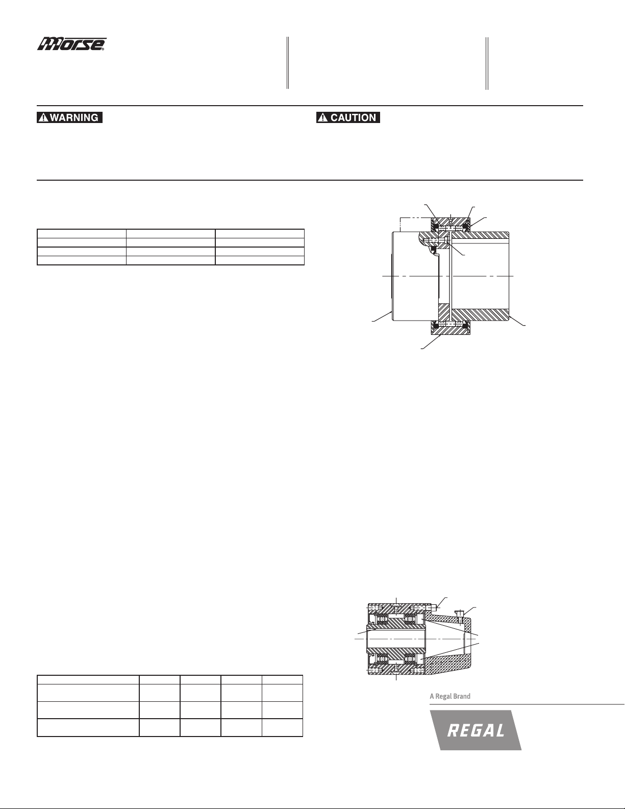
Clutch with Oil Reservoir
Remove
seal at
reservoir
end
Apply
Permatex
or
similar
sealant
Oil ll
Capscrews
Clutch Coupling
Seal
Retainer
plate
Hub gear
Ring assembly
Clutch
Capscrews
Plate gear
Nominal Diameter Bore Shaft
2" Dia. & Smaller “ + .000 — .001" -.001 — .002"
Over 2" to 4" + .000 — .0015" -.0015 — .0025"
Over 4" + .000 — .002" -.002 — .003"
Coupling Number C-7.5 C-8 C-9 C-10
Maximum Angular
Misalignment 1/2° 1/2° 1/2° 1/2°
Maximum Parallel
Misalignment .010" .010" .010" .010"
Allowable End Float From +1/4" +1/4" +1/4" +1/4"
Nominal 11/16” Gap -5/8" -5/8" -5/8" -5/8"


