Labelmate RRC-400 User manual

-
RRC-400
Reel-to-Reel Counter / Rewinder
User Manual
www.labelmateusa.com

Page 2
• Any machine can be dangerous to operators when improperly used or poorly maintained.
• All employees operang and maintaining Labelmate equipment should be instructed on correct use and
safety guidelines.
• Most accidents are preventable if adequate precauons are taken.
• Be aware of safety labels and instruconal decals that have been placed near any potenal hazards.
It is the responsibility of the customer to ensure that all personnel are instructed on proper operaon of
Labelmate equipment prior to use. All personnel operang, inspecng, servicing, or cleaning this equipment
must be properly trained in operaon and machine safety. Read all operang instrucons before using this
equipment.
• Ensure that all power sources are turned o when the machine is not in use.
• Read the manual for any special operaonal instrucons for each piece of equipment; user manuals are
included in the product packaging and/or can be found on the website www.labelmateusa.com.
• Know how the equipment funcons and understand the operang processes.
• Know how to shut down the equipment.
• Understand the equipment safety labels.
• Wear the appropriate personal protecve equipment for the job to be performed (eg: eye protecon,
gloves, safety shoes, etc.).
• When working on or around all equipment, avoid wearing loose clothing, jewelry, unrestrained long hair,
or any loose es, belts, scarves, or arcles that may be caught in moving parts.
• Keep all extremies away from moving parts; entanglement could cause severe injury or death.
• For new equipment, check plant voltage with the voltage specied on the machine; electrical specica-
ons for this machine are printed on the power adaptor used with the machine.
• A properly grounded electrical receptacle is required for safe operaon regardless of voltage require-
ments.
• Use the equipment for its intended purpose only.
Safety First
Page 3
• Keep the operang zone free of obstacles that could cause a person to trip or fall toward an operang
machine.
• Do not operate machinery if you are fagued, emoonally distressed, or under the inuence of drugs or
alcohol.
• Know where the rst aid safety staon is located.
• Use proper liing and transporng devices for heavy equipment.
• Any machine with moving parts and/or electrical components can be potenally dangerous no maer
how many safety features it contains. Stay alert and think clearly while operang or servicing the equip-
ment. Be aware of operaons and personnel in your surroundings. Be aenve to indicator lights and/or
operator interface screens displayed on the machine and know how to respond.
-
The RRC-400 is equipped with built-in safety features. These features are for the safety of the operator and
the reliability of the machine.
• Motors accelerate and decelerate to desired speed to prevent electrical current from overpowering the cir-
cuitry in the machine
• Depending on the input speed and direcon selected, the maximum speed of one of the motors will not
exceed a designated threshold, and the right side motor will always overpower the le side motor when
speeds are idencal. This decreases the amount of current experienced by the internal circuitry and reduc-
es the possibility of the unwind motor overcoming the rewind motor due to user input.
• The RRC-400 slows down at the end of the roll to ensure accurate counts and to prevent the label backing
from breaking due to excess speed.
• : “-” -

Page 4
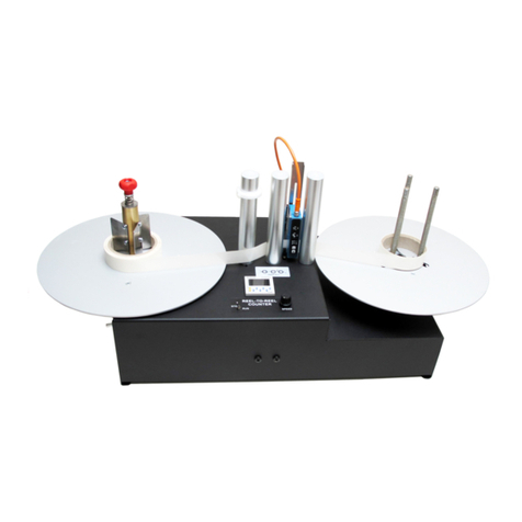
Reel-to-Reel Counters provide the ideal o-line soluon for counng rolls of labels. With these machines you
can verify the number of labels on a roll, divide large rolls into smaller rolls using the preset count/stop fea-
ture, and re-tension loose rolls. The RRC-400 aords high-speed bi-direconal counng capability for up to
16” diameter rolls.
• RRC-400 user manual (this document)
• Sensor user manual (Ultrasonic model only)
• Counter user manual
• RRC-400 Unit
• Power Supply: PS-160
INPUT: 100-240VAC 50/60Hz
OUTPUT: 24VDC 6.6A
• 2X Exterior Roll Guide Bracket and Support Sha
• 2X Core Holders (Desired opons selected at me of order)
• Weight of the machine without core holders: 52 lbs. (23.5kg)
• Max Label Roll Weight: 50 lbs. (23kg)
• Max Label Roll Diameter: 16in. (406mm)
• Dimensions (HWD): 20x40x16in. (508x1016x406mm)
RRC-400
80-238-0013 RRC-400 Reel-to-Reel Counter, opaque labels only
80-238-0014 RRC-400-UUltrasonic Reel-to-Reel Counter, opaque & transparent labels
-
81-197-0020 RR-C76-170 3” diam. Quick-Locking Core-Chuck, 6” tall
81-197-0021 RR-C76-220 3” diam. Quick-Locking Core-Chuck, 8” tall
81-246-0005 ACH-RR-400 Adjustable 1” - 4” diam. Roll-Holder Assembly, 6” tall
-
81-141-0006 RRC-ENC Encoder for linear count/measurement

FIG. 1 FIG. 2
FIG. 3
“”
Page 5
• The Guide Bracket is used to maintain a ush outer roll edge.
• The Guide Bracket Shas are mounted in the two upper corners of the unit.
• Lay the counter on its back so the inside is visible.
• Remove hardware from the Shas and install them in the upper corners of the unit using the M13 bolt
and nut on the inside of the machine as shown.
• With your hand, turn each motor sha so that the at of the shas face the nearest outside edge of the
machine.
• Slide the core holder assemblies onto the motor shas.
• Tighten both set-screws in the core-holder assemblies onto the of the motor shas using
the provided Allen wrench unl they are ght.
• Both the “Quick-Chuck” and ACH Core-Holders are installed idencally.

Page 6
-
• Slide a label roll or empty label core over the “Quick-Chuck” and turn the red lock knob clockwise unl it
is ght.
• When using narrow label cores the outer edge of the “Quick-Chuck” must be constrained to ensure that
the “Quick-Chuck” expands evenly. To do this, simply squeeze the outer edge of the “Quick-Chuck” with
your hand, or place another label core of the same size toward the outer edge of the “Quick-Chuck” as
you ghten the red lock knob.
• To remove the roll or label core, turn the lock knob counter-clockwise unl the “Quick-Chuck” relaxes,
and gently li the roll o the machine.
FIG. 6
-
-
FIG. 4 FIG. 5
-
“-”
FIG. 7

Page 7
• Unlock the three locking levers underneath the plate by turning them clockwise.
• If any of the levers are difficult to grasp, pull the lever arm down, and turn the arm to reposition it so that it is approxi-
mately perpendicular to the cylindrical metal hub.
• While holding the upper plate firmly, rotate the black plate beneath it to contract the three knurled “fingers” together
that comprise the core-holder.
• Place an empty core over the “ngers” about half-way down and rotate the black plate again to bring the
“ngers” in contact with the core.
• Remove the empty core and expand the “ngers” an addional 1/16 of an inch in order to prevent the core
from slipping.
• Lock the locking levers by turning them counter-clockwise.
• Reposion the lever arms if necessary by pulling straight down and rotang them to a convenient posion.
• Press the empty core all the way down onto the expanded “ngers”.
• The core should now be held ght on the “ngers”; If it is not ght enough, re-do the operaon.
• When sased with the t, the empty core can be removed and a full roll with the same core size can be
pressed onto the ngers and against the plate.
• For easy removal of the roll from the ACH, release one of the locking levers temporarily, remove the roll and
re-ghten the locking lever.
• Once the ACH diameter is set, the next empty core or roll can be placed on the
ACH without readjusng the locking levers.
Upper Plate
Black Plate
FIG. 8 FIG. 9
FIG. 10
FIG. 11 FIG. 12 FIG. 13

Page 8
• Place both direcon switches to the center-o posion (illustrated by the “|” symbol).
• Place the label liner only (no label) into the label gap sensor.
• Turn the Photocell Adjust knob located on the le hand side of the counter unl the green Photocell Ad-
just LED above the Counter Reset buon illuminates.
• Remove the label liner from the label gap sensor.
--
• Once the labels have been threaded through the label sensor, press and hold the “T” buon, located on
the front of the sensor, unl the green and yellow LED’s ash simultaneously.
• Release the “T” buon and advance the label stock through the sensor unl the LED’s stop ashing and
only the green LED remains illuminated.
• Manually rotate the supply roll unl the rst label you want to count is properly posioned.
• Reset the counter to 0 and start the unit.
FIG. 14 FIG. 15
FIG. 16

Page 9
---
• Opaque labels and liners: Flip the switch on the lower front le side of the unit to OPAQUE.
• Transparent labels and liners: Flip the switch on the lower front le side of the unit to TRANSPARENT.
FIG. 18 FIG. 19
--
-
“”
FIG. 17

Page 10
-
• The damper rollers at the top of the machine should be slightly separated from the aluminum rollers such
that the labels are close but do not touch the rubber rollers.
• The rubber rollers help prevent any variance in the nal count by prevenng the uering of the web at
the end of the roll from being felt by the label sensor as the web is pulled o of the unwind side of the
machine.
• The rubber rollers can be adjusted forward and backward by loosening the screw with a Phillips head
screw driver and ghtening it again once it is in the desired posion.
FIG. 20

Page 11
-
• Place both direction switches in the stop position (illustrated by the “|” symbol).
• Place the supply roll of labels onto a core holder on one side of the machine.
• Install an empty label core onto the other side of the machine and tighten the Core-Holder.
• Thread the labels from the supply behind the guide rollers and through the label sensor(s).
• If desired, posion the guide brackets over the top of the rolls (recommended). . This helps pre-
vent the web from rising during the counng process, and ensures a ush and consistent roll edge.
• The guide brackets also generate a small amount of fricon with the unwind roll, which can increase the
tension and compactness of the nish-roll.
• If desired, another opon is to set the white label guide rings on the center aluminum rollers so that they
hover just above the label web. This also helps prevent the web from rising during the counng
process in order to ensure a ush and consistent roll edge.
• Reset the counter to zero.
• Set the “SYNC” switch to the desired mode (On or O). If “On”. The blue LED will illuminate.
Top View
FIG. 22
FIG. 23
FIG. 21

Page 12
-
• Sync Mode enables semi-automac operaon. Once the operator has chosen the desired direcon and
speed, the machine will automacally adjust the speed throughout the counng process to opmize the
counng me and roll tension.
• Place the “SYNC” switch in the up posion, and the blue LED above the switch will illuminate to indicate
that Sync Mode has been acvated.
• While in Sync Mode, . Direcon and max speed are set for both
motors using the “LEFT/SYNC” switch and speed dial.
• While in Sync Mode, rollers must unwind and rewind from the outside as shown in .
• Set the “LEFT/SYNC” speed control to desired max speed - ull clockwise rotaon for max speed, full
counter-clockwise rotaon for no speed.
• Set the “LEFT/SYNC” direcon switch so the arrow is pointed in the desired ow direcon (toward the
rewind side).
• The machine will begin counng. You may noce it will speed up and slow down automacally through-
out the counng process. This is intenonal as the machine is opmizing for tension and speed.
FIG. 24
FIG. 25
FIG. 26

Page 13
• Manual Mode gives the user complete control over the operaon of the machine. The two bidireconal
motors enable the rewinding and unwinding in any direcon and any conguraon. .
• Each motor has its own direcon and speed control.
• The arrows under each switch indicate the direcon the motors will turn.
• “<” Sets the motor to turn counterclockwise.
• “>” Sets the motor to turn clockwise.
• “|” Center posion stops the motor.
• The speed control increases the speed and torque of each respecve motor.
• Full clockwise rotaon for max speed and torque.
• Full counterclockwise rotaon for no speed or torque.
• The machine will automacally slow down at the end of the roll to ensure an accurate count.
FIG. 27
FIG. 28

Page 14
• The counter is counng the gaps between the labels, and will increase by one for each label that passes
through the sensor.
• To use the preset funcon, input the desired number of labels with the blue push buons on the counter.
Each buon increases the preset count by its respecve order of magnitude.
• When the preset number of labels is reached, the RRC-400 will stop as close to the desired count as possi-
ble. Pressing the white “COUNTER RESET” buon to the le of the counter will start the RRC-400 again.
• The motors will “coast” a lile aer reaching the preset count, and the counter will indicate how many
labels beyond the preset have been counted.
• In order to precisely achieve the desired preset amount, manually rotate the unwind sha backwards by
the amount of the overage.
-
-
The Encoder Opon provides the exibility to measure the linear length of a material or numerically count
labels with inter-label gaps, and/or labels without gaps.
• Load label roll as previously outlined herein (pgs. 16 - 20) and thread the material through the Rollers in
either one of the two ways shown.
• Flip the switch on the lower front le side of the unit to TRANSPARENT.
• On the Counter, press “SET/LOCK” key and “UP” (far top right key) together at the same me. SCLE ap-
pears in the display.
• Enter the desired SCALE FACTOR from the chart on the next page (pg. 21). The values shown are the cal-
culated Scale Factor Values for readout in various units.
• Press the RESET key for the change to take eect.
• The readout will now display the length of material wound as it passes the Encoder.

Page 15
Label Label Label
FIG. 29
FIG. 30
FIG. 31
FIG. 32
“”

Page 16
-
Millimeters (mm) 4.555
Centimeters (cm) 0.456
Meters (M) 0.004
Inches (in) 0.179
Feet (ft) 0.015
-
• Flip the switch on the lower front le side of the unit to OPAQUE.
• If a pre-scale value was previously set, the value will need to be reset to 1.
• On the Counter, press “SET/LOCK” key and “UP” (far top right key) together at the same me. SCLE ap-
pears in the display.
• Set the SCALE FACTOR to 1.000.
• Press the RESET key for the change to take eect.
-
• Flip the switch on the lower front le side of the unit to TRANSPARENT.
• On the Counter, press “SET/LOCK key” and “UP” (far top right key) together at the same me. SCLE ap-
pears in the display.
• Calculate the SCALE FACTOR by dividing the SCALE FACTOR from the chart above by the measured length
from the leading edge of one label to the leading edge of the next label. Use the SCALE FACTOR
from the chart above that corresponds to the unit of measurement used to measure the label.
• For best results measure the labels in mm.
• Press the RESET key for the change to take eect.
NOTE: If you want the Unit to stop automacally at a given number of Labels, key in the length of materi-
al or number of labels at which you want the machine to stop. (See PRESET COUNT instrucons on
the top of page 20.)

Page 16
- “” “”
“”
-
Excluding Counter Displays and Encoders
Excluding Counter Displays
Mechanical Parts Only - excluding Counter Displays
--Excluding Counter Displays and Encoders
Excluding Counter Displays and Encoders
-
-
- --
Labelmate USA warrants to the original end-user customer that Labelmate USA products will be free from
defects in materials and workmanship for the duration described herein below. Labelmate USA’s Limited
Warranty covers only those defects that arise as a result of normal use of the products and does not cover
any other problems, including those that arise as a result of: (i) improper maintenance or modification; (ii)
parts or supplies not provided or supported by Labelmate USA; (iii) operation outside the products’ specifica-
tions; or (iv) unauthorized repair, modification or misuse. Use of any unauthorized accessory or attachment
will void coverage.
The Warranty period for all products commences the date of shipment from Labelmate USA and accrues to
the original end-user customer. Warranty coverage is non-transferable and terminates immediately upon rent-
al, resale or any other change in ownership. Original purchase documentation should be retained for Warran-
ty coverage verification.
In the event Labelmate USA substantiates, during the applicable Warranty period, a defect in any product
which is covered by Labelmate USA’s Warranty, Labelmate USA shall repair or replace the product, at Label-
mate USA’s option. Labelmate USA retains sole discretion to determine whether or not a product is defective.
In no event shall Labelmate USA have any obligation to repair or replace until the customer returns the defec-
tive product to Labelmate USA. The customer assumes any and all responsibility and liability associated with
transportation of products for service under this Warranty.
In the event your product requires service or you have questions regarding Warranty coverage, please call
toll-free (877) 833-7149 inside the United States, or +1 (702) 435-8535 outside the United States.
LABELMATE MAKES NO OTHER WARRANTY OF ANY KIND, WHETHER EXPRESS OR IMPLIED WAR-
RANTIES OR CONDITIONS OF MERCHANTABILITY, SATISFACTORY QUALITY, AND/OR FITNESS FOR
A PARTICULAR PURPOSE. NO OTHER PERSON, AGENT, DEALER OR RESELLER IS AUTHORIZED TO
GIVE ANY WARRANTIES ON BEHALF OF LABELMATE. ANY OBLIGATION TO WARRANTY OTHER
THAN THAT SPECIFICALLY ADDRESSED HEREIN IS EXPRESSLY DISCLAIMED.

Toll Free: 877.833.7149
Direct: 702.435.8535
12A Sunset Way
Henderson, NV 89014
Table of contents
Other Labelmate Cash Counter manuals

Labelmate
Labelmate Count-100 User manual

Labelmate
Labelmate RRC-330-U User manual

Labelmate
Labelmate COUNT-200-DELUXE-US User manual

Labelmate
Labelmate RRC-330 User manual

Labelmate
Labelmate Count-100 User manual

Labelmate
Labelmate DISTRI-ST User manual

Labelmate
Labelmate RRC-330 User manual

Labelmate
Labelmate RRC-330 User manual

Labelmate
Labelmate RRC-330 User manual

Labelmate
Labelmate COUNT-100-DELUXE-US User manual