Casio EV-600B Troubleshooting guide
R
EV-600B(NTSC)
SEPT. 1997
(without price)
(KX-613)

— 1 —
CONTENTS
SPECIFICATIONS ......................................................................................... 2
BLOCK DIAGRAM ........................................................................................ 3
TROUBLESHOOTING................................................................................... 4
PRINTED CIRCUIT BOARDS ....................................................................... 5
EXPLODED VIEW ......................................................................................... 7
PARTS LIST .................................................................................................. 8
SCHEMATIC DIAGRAMS ........................................................................... 11
WAVEFORMS.............................................................................................. 13

— 2 —
SPECIFICATIONS
Item Specification
1. Reception channels
2. Power voltage DC 6.0 V
3. Power consumption Approx. 3.8 W
4. Current consumption Approx. 630 mA
5. Battery life (with alkaline batteries) Approx. 2.0 hours
Batteries : 3 AA size batteries
6. Power supply Car adaptor : CA-K65
AC adaptor : AD-K64
Earphone jack : 3.5ø mini
7. Connection terminals External power jack : 6.0 V DC IN
External antenna jack : 3.5ø mini
Audio / Video jack : 3.5ø
8. Screen size 3.0 inches
9. No. of Picture element 75,816 (234 ×324) dots
10. Dimensions 125.0 (W) ×32.0 (D) ×101.2 (H) mm
11. Weight 290 g excepting batteries
AC adaptor : AD-K65,64
12. Options Car adaptor : CA-K65
RF connector : CF-13
Antenna matching device : AS-35S
AV cord : AV-C1
VHF: 2 ~ 13 ch UHF: 14 ~ 69 ch
— 3 —
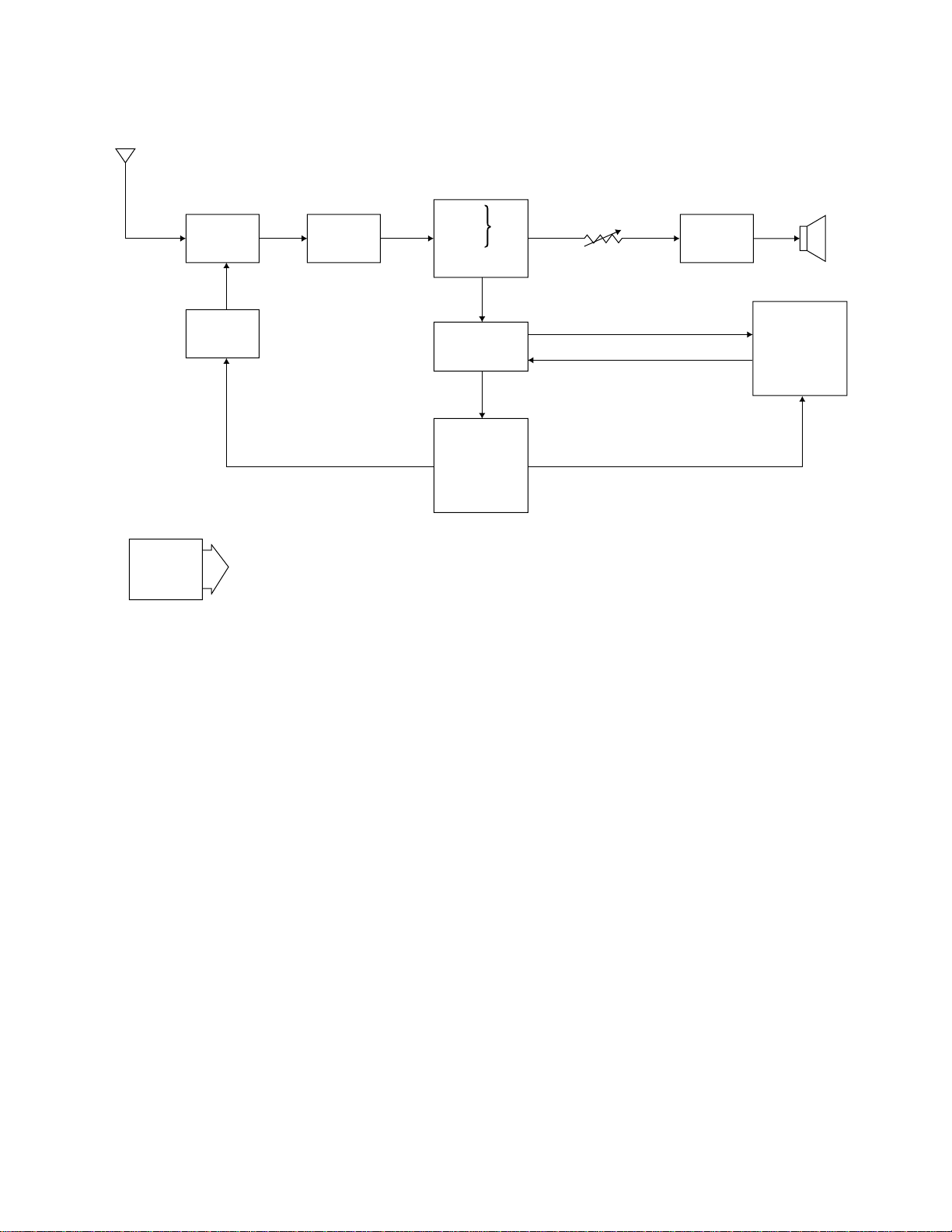
1— Color tuner: TU200 TEPU5-02
Selects a desired radio wave and changes it to the video IF signal.
2— Video IF amp.: Q200 2SC4238
Amplifies the video IF signal output from tuner TU200 by 10 times (20 dB).
3— Video det./Sound det./FM det./AFT/AGC: IC200 M51348AVP
Eliminatesthe carrier wavein the videoIF signal, andpicks up thevideo signal andthe sound IFsignal.
Also, the sound signal is picked up from the sound IF signal by FM detection.
4— Audio amp.: IC600 NJM2070M
Sound amplification.
5— Chroma circuit: IC300 IR3P90Y
Generates the tricolor (red, green, and blue) from the video signal.
6— Display control/Auto-tuning control: IC400 LZ93BA5
Controls the display.
7— Tuning voltage generator: IC501 BA10358F
Generates the tuning voltage with the tuning pulse output from 6.
BLOCK DIAGRAM
Antenna
1
7
24
Speaker
VR600
IC501 IC300
IC400
Volume
Control
3
5
6
Power
Supply
VCC2 (5.0 ±0.02 V)
VCC7 (28.8 ±2.9 V)
VCC6 (9.1 ±0.5 V)
VEE1 (–20.0 ±2.0 V)
VEE2 (–8.1 ±0.8 V)
Display
Control
Auto-Tuning
Control
Chroma
Circuit
Tuning
Voltage
Generator
Tuner IF Amp.
LCD
Audio
Amp.
Video
Sound Det.
FM
AFT Circuit
AGC Circuit
TU200 Q200 IC200 IC600
— 4 —
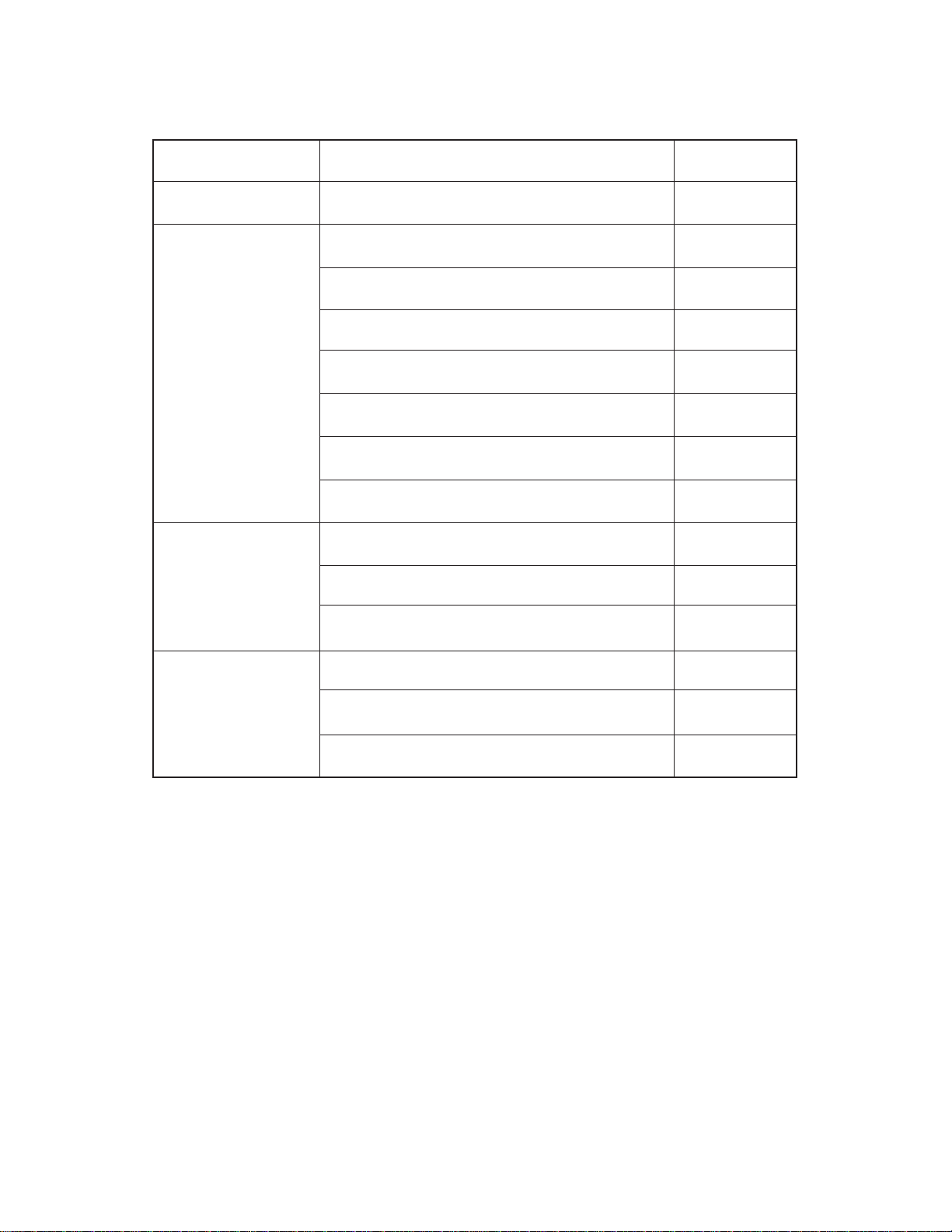
Symptom Cause Solution
No power supply Defective power switch (SW100). Replace.
Defective DC-DC converter (T100). Replace.
Defective tuner (TU200). Replace.
Defective Q200. Replace.
Defective IC200. Replace.
Defective IC300. Replace.
Defective IC400. Replace.
Defective IC501. Replace.
Defective IC200. Replace.
Defective IC600. Replace.
Defective phone jack (JK600). Replace.
Defective tuner (TU200). Replace.
Defective IC501. Replace.
Defective power switch (SW100). Replace.
TROUBLESHOOTING
Picture OK but
no sound
No reception of
VHF or UHF
No picture and
no sound
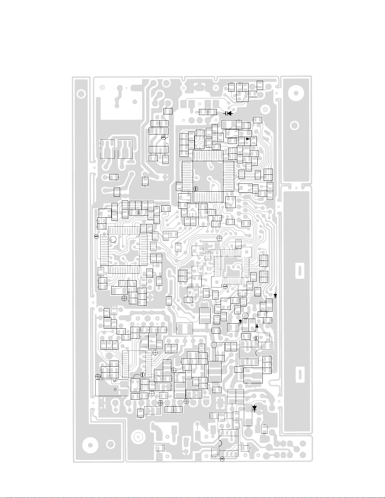
— 5 —
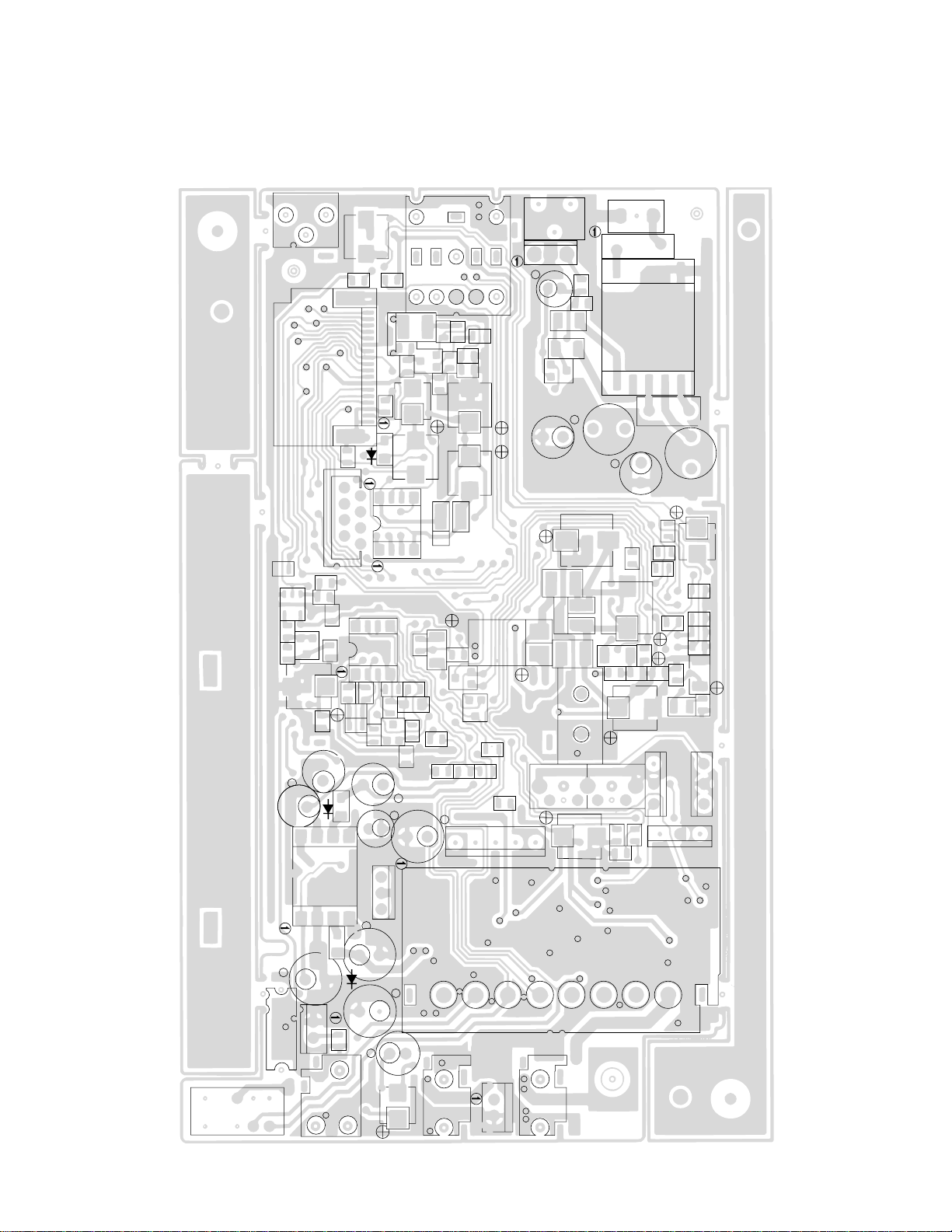
PRINTED CIRCUIT BOARD
TOP VIEW
Linear
CN900
SW900
CN901
R905
C351
L305
C358
F203
F201
C927
T950
R951
C901
R950
Q900
C911 L951
C910
C352
C313
C312
L950
R324
C300
L300
F202
C256
JK200JK600
JK100
FU100
SW100
C610
C131
C100
T100
C120
C119
R555
C510
C115
CN101
R557 R577
C500
D500
R566
C551
R570 R569
D501
C432
C556
IC502
C118
C116
C550
C553 R553 R568
L205
R550
D504
C552
IC501
R580
C160
C403
C405
R452
C452
L403
L505
C315
VR301
JK300
CN400
CN500
C561
Q503
D503
T201
R578
F200
CN600
T200
C310
— 6 —
BOTTOM VIEW
Linear
CP310
R329
Q300
R303
C436
CP465
CP457
CP421
CP408
R420
C565
C250 R562
R579
R224
R130
R639
C630
R600
D105
R102
D115
R425 R426
R431
R441
R903
C952
C458
R401
C430
R551
VCC2
C206
R230 R242
R225
R250
R315
L506
VR302
C364
R305
R301 C950
R300
C375
C368
C257
C249
R222
C230
R208
R552
C405
C447
C445
C446
CP426
C434
R416
VR400
CP452
CP343
CP240
CP602
CP320
L507
C558
R585
R565
R564
Q500
C150
D114
C156
C142
R103
C141
CP102
Q103
C633
IC600
IC100
C152
L110 C143
R411
R410
C511
R405
R400
C373
L307
CP336
Q504
L306
R321
C951
R319
CP339
D502
Q501
L500
L201
L200
C236
R232
C262
C362
C301
R308
IC300
R312
R313
C200
C233C232
IC200
CP213
CP218
CP308
CP324
L203
C271
C231 CP230
C153
VR100
R567
R572
CP334
CP332
R571
VR405
C431
C433
D406
D402
R433
C953
R901R902
R904
Q951 Q950
R442
IC900
IC400
CP237CP238
CP239
C202

— 7 —
EXPLODED VIEW
1
2
3
3-1
7
4
32
33
56
8
9
10
32
33
10-1
11-1
11-2 32
11
12
33
16
17
18
14
15
13
33
32
17-1
18
19
20
21
22
23
24
25
33
31
30
29
28
26
27
12
32

PARTS LIST
LINEAR PCB
Item Code No. Parts Name Specification Applicable Q R
Diodes
D105 2390 2450 DIODE/CHIP SC016-2-TE12RA EV-600B Common 1C
D110, D111,D113 7101 1194 DIODE/CHIP MA111-(TX) EV-600B Common 3C
D112 2390 1379 DIODE/SCHOTTOKY MA729-(TX) EV-600B Common 1C
D114,D406,D500 2390 1470 DIODE/CHIP MA143A-(TX) EV-600B Common 3C
D115 2360 2303 DIODE/ZENER MA8091-M(TX) EV-600B Common 1C
D200,D405,D501 2390 0455 DIODE/CHIP MA142K-(TX) EV-600B Common 3C
D400 2360 1876 DIODE/ZENER MA8100-M(TX) EV-600B Common 1C
D402 2390 1358 DIODE/ZENER MA329-(TX) EV-600B Common 1C
D403 2360 2296 DIODE/ZENER MA8056-M(TX) EV-600B Common 1C
D502 2390 1183 DIODE/CHIP MA142WK-(TX) EV-600B Common 1C
D503 2390 1477 DIODE/CHIP MA142WA-(TX) EV-600B Common 1C
Fuse
FU100 3632 0322 FUSE NT1-1A EV-600B Common 1B
ICs
IC100 2114 3150 IC MB3776APNF-EF EV-600B Common 1C
IC200 2114 2471 IC/LINEAR M51348AVP-T1 EV-600B Common 1C
IC300 2114 3633 IC/LINEAR IR3P90Y-1 EV-600B Common 1C
IC400 2114 3367 IC LZ93BA5-1 EV-600B Common 1C
IC402 2114 5766 OP AMP NJM3414AM-T1 EV-600B Common 1C
IC403 2259 2733 TRANSISTOR ARRAY FMC1A-T148 EV-600B Common 1C
IC404 2114 2674 OP AMP NJM2107F-TE1 EV-600B Common 1C
IC500 2114 3374 IC SED3950FOC EV-600B Common 1C
IC501 2116 0119 OP AMP BA10358F-T1 EV-600B Common 1C
IC502 2105 0777 IC/L-MOS TC4S81F-TE85L EV-600B Common 1C
IC600 2114 2464 IC/LINEAR NJM2070M-T1 EV-600B Common 1C
IC900 2114 1736 IC BA10393F-T1 EV-600B Common 1C
Jacks
JK100 3501 8281 JACK HEC0811-010010 EV-600B Common 1C
JK200,JK600 3501 5439 JACK HSJ1456-01-210 EV-600B Common 2C
JK300 3501 3773 JACK HSJ6063-01-410 EV-600B Common 1C
Transistors
Q103,Q950,Q951 2253 0308 TRANSISTOR/CHIP 2SD1119-R(TX) EV-600B Common 3C
Q200 2252 0707 TRANSISTOR/CHIP 2SC4238-(TX) EV-600B Common 1C
Q300,Q500,Q504 2252 0637 TRANSISTOR/CHIP 2SC4081-T106R EV-600B Common 3C
Q400 2253 0665 TRANSISTOR/CHIP 2SC4182-T2T33,34 EV-600B Common 1C
Q501 7911 0126 TRANSISTOR/DIGITAL DTC144EUA-T106 EV-600B Common 1C
Q502,Q503 2259 2625 TRANSISTOR/DIGITAL DTC144TUA-T106 EV-600B Common 2C
Q900 7911 3045 TRANSISTOR/DIGITAL DTA114YUA-T106 EV-600B Common 1C
Switches
SW100 3412 0798 SWITCH/SLIDE ESD-11H231 EV-600B Common 1C
SW900 3412 0840 SWITCH/SLIDE ESD-11H121 EV-600B Common 1C
Converter
T100 3701 0637 DC-DC CONVERTER CEE98-04 EV-600B Common 1B
T950 3012 1078 INVERTER TRANS ETJ-11K010AM EV-600B Common 1B
Tuner
TU200 1013 5511 TUNER TEPU5-02 EV-600B Common 1C
Variable resistor
VR301 2775 0077 RESISTOR/SEMI-FIXED H0614D-47KB EV-600B Common 1C
Notes: Q – Quantity used per unit
R – Rank — 8 —

KEY PCB
Item Code No. Parts Name Specification Applicable Q R
LED
D120 2370 1260 LED SLC-22VR3F EV-600B Common 1C
Switch
SW300,SW301,SW302 3412 1029 SWITCH SKHHAL EV-600B Common 3C
Variable resistors
VR303 2765 0623 VOLUME RK09H11T-20KB EV-600B Common 1C
VR600 2765 1582 VOLUME RK09H11T-100KB EV-600B Common 1C
Notes: Q – Quantity used per unit
R – Rank — 9 —
Other manuals for EV-600B
1
This manual suits for next models
1
Table of contents
Other Casio Portable TV manuals

Casio
Casio TV-600G Troubleshooting guide

Casio
Casio TV-880C User manual

Casio
Casio TV-600D User manual

Casio
Casio TV-770C Troubleshooting guide

Casio
Casio EV-2500C Troubleshooting guide

Casio
Casio TV-1450C User manual

Casio
Casio EV-510C Troubleshooting guide

Casio
Casio FV-600P Troubleshooting guide

Casio
Casio TV-880B Troubleshooting guide

Casio
Casio TV-600B Troubleshooting guide


