— 3 —
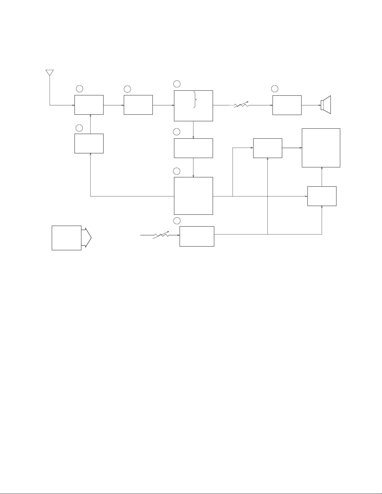
Antenna
1 TU200 2 Q200 3 IC200
7
Tuning
Voltage
Generator
VR600
Volume
Control
4 IC600 Speaker
IC300
IC700
Common
Driver LCD
Segment
Driver
Chroma
Circuit
OSC
Display
Control
A-D Converter
Auto-Tuning
Control
5
6
8 Q800 ~ Q806
VR800 Display
Voltage
Generator
Brightness
Control
VCC2 (3.95V±0.02V)
VCC6 (30.5 ~ 39.0V)
VCC7 (53.5 ~ 72.5V)
VEE1 (-6.3 ~ -7.9V)
IC500
Power
Supply
Audio
Amp.
IF Amp.Tuner
Video
Sound Det.
FM
AFT Circuit
AGC Circuit
BLOCK DIAGRAM
1— Color Tuner: TU200 TEPE5-01
Selects a desired radio wave and changes it to the video IF signal.
2— Video IF Amp.: Q200 2SC4238
Amplifies the video IF signal output from the tuner TU by 10 times (20dB).
3— Video Det./Sound Det./FM Det./AFT/AGC: IC200 M51348FP
EliminatesthecarrierwaveinthevideoIFsignal,andpicksupthevideosignalandthesoundIFsignal.
Also, the sound signal is picked up from the sound IF signal by FM detection.
4— Audio Amp.: IC600 NJM2070M
Sound amplification.
5— Chroma Circuit: IC300 M52045FP
Generates the tricolor (red, green, and blue) from the video signal.
6— OSC/A-D Converter/Display control/ Auto-Tuning Control : IC700 MSM662502 GSK-640F
Converts the color signal into a digital signal.
Also, generates the clock pulse for the display and controls the display.
7— Tuning Voltage Generator: IC500 MSC1169MS-K
Generates the tuning voltage with the tuning pulse (TU) output from 6.
8— Display Voltage Generator: Q800 ~ Q806 2SB1218A-R, 2SD1824R, S ×2, 2SD1819A-R ×5,
2SD1824-5
Generates the display voltages V0 ~ V4 with VEE1 and VCC7 outputs from the power supply.