Casio TV-M430S Troubleshooting guide

CONTENTS
SPECIFICATIONS ......................................................................................... 1
BLOCK DIAGRAM ....................................................................................... 2
SETTING THE SYSTEM SELECTOR ........................................................... 3
ADJUSTMENT............................................................................................... 4
DISASSEMBLY ........................................................................................... 10
PRINTED CIRCUIT BOARDS ..................................................................... 13
EXPLODED VIEW ....................................................................................... 15
PARTS LIST ................................................................................................ 16
SCHEMATIC DIAGRAMS ........................................................................... 17

— 1 —
SPECIFICATIONS
1. Type LCD Color Television
2. Reception Frequencies UHF: UHF band
CH 21 – CH 69 (CCIR, O.I.R.T., F.O.T.)
CH 21 – CH 68 (U.K.)
CH 13 – CH 57 (CHINA)
VHF: VHF band
CH 2 – CH 12 (CCIR)
CH 1 – CH 12 (CHINA, O.I.R.T.)
CH 4 – CH 9 (F.O.T.)
3. Display Element: High resolution color liquid crystal display (TN Type)
4. Drive System: TFT active matrix system
5. Screen Size: 4.0 inches
6. Backlight: High luminance fluorescent material
7. Antenna: Rod antenna (VHF, UHF)
8. Speaker: 11/8ø inches (28 mm) x 1
9. Connection Terminals: Earphone jack (3.5ø mini)
External power source jack (DC IN 12V)
Audio/Video input jack (3.5ø mini)
External Antenna jack (3.5ø mini)
10. Power Supply: 2-way power supply system
AC: AC adaptor AD-K1200 (option)
Car battery: Car battery cord CA-K1200 (accessories)
11. Power Consumption: Approx. 6.8 W
12. Ambient Temperature Range: 32°F (0°C) ~ 104°F (40°C)
13. Dimensions: 14.6 x 3.4 x 12.0 cm
14. Weight (excluding batteries): Approx. 340 g
Item Specification

— 2 —
SETTING THE SYSTEM SELECTOR
You can set the TV to receive signals for any one of seven different television systems. This means that the
TV can be adjusted to suit the tuning requirements of almost any geographic area in the world.
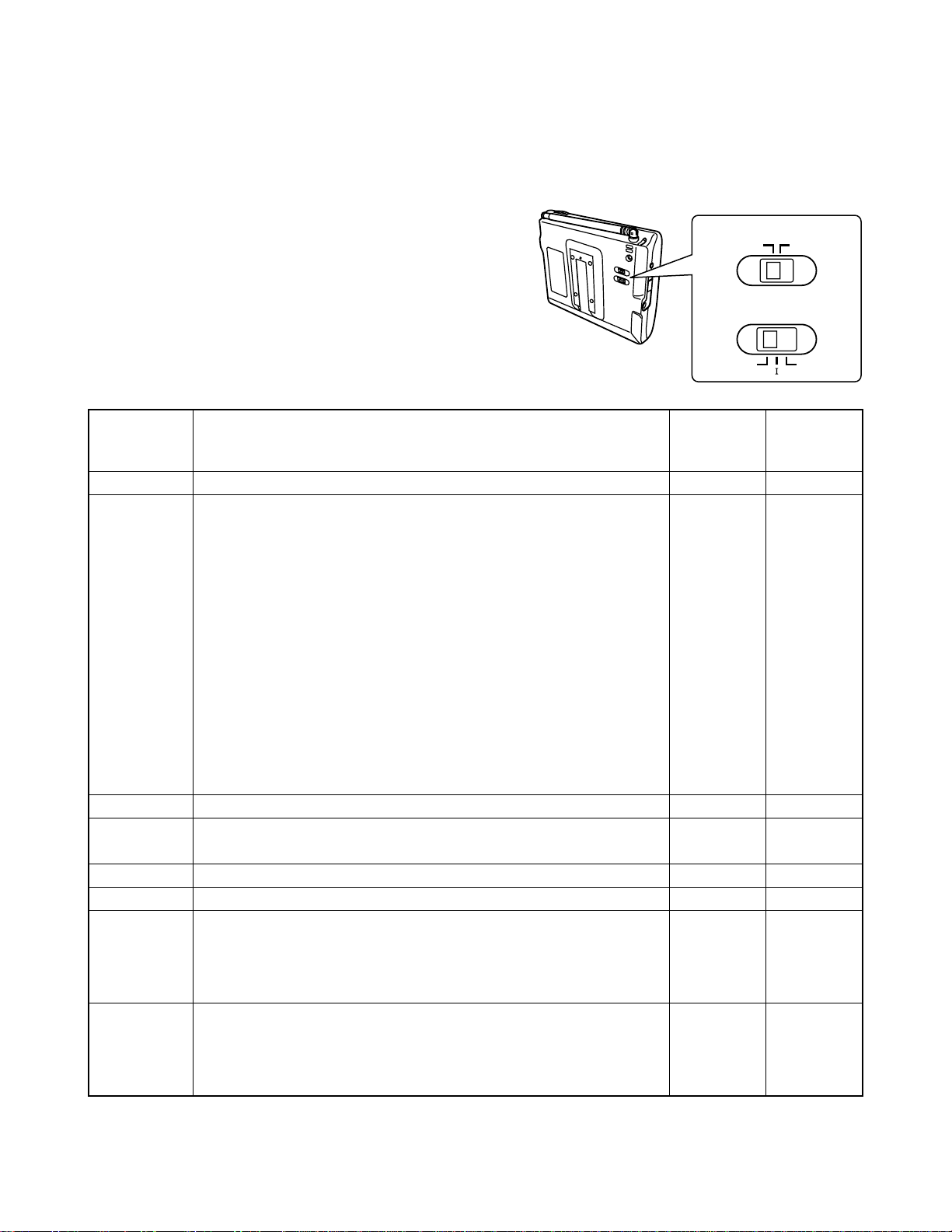
Setting the Color system selector and TV system selector
Find the name of the country where you will be using the TV
in the table below, and then set your TV’s color system
selector and TV system selector accordingly.
COLOR
SECAMPAL
TV SYSTEM
D,K’/KB/G,H
Area
(Angola) / Hong Kong /(Ireland) / (Lesotho) / (South Africa) / U.K.
Afghanistan / (Albania) / Algeria / (Australia) / Austria / Bahrain /
Bangladesh / Belgium / Bosnia Herzegovina / Brunei / Cambodia
/ Cameroon / (Croatia) / Cyprus / Denmark / Ethiopia / Finland /
Germany / Ghana / Gibraltar / Greenland / Iceland / India /
(Indonesia) / Israel / Italy / Jordan / Kenya / Kuwait / (Laos) /
(Libya) / (Lithuania) / Luxembourg / Macedonia / Malaysia /
Maldives / Malta / (Monaco) / Mozambique / Nepal / Netherlands
/ (New Zealand) / Nigeria / Norway / Oman / Pakistan / Papua
New Guinea / Portugal / Qatar / (San Marino) / Seychelles / Sierra
Leone / Singapore / Spain / Sri Lanka / Slovenia / Sudan /
Swaziland / Sweden / Switzerland / Syrian Arab Republic /
Tanzania / Thailand / Turkey / Uganda / United Arab Emirates /
Yemen / (Yugoslavia) / Zambia / Zimbabwe
Albania / Italy
Cyprus / Egypt / Equatorial Guinea / Greece / Iran / Iraq / Lebanon
/ Mauritania / Mauritius / (Morocco) / Saudi Arabia / Tunisia
China
Hungary / North Korea / Poland / (Romania)
Benin / Burundi / Chad / (Congo) / Djibouti / Gabon / Guadeloupe
/ Guiana / (Ivory coast) / Madagascar / Mali / Martinique / New
Caledonia / Niger / Polynesia / Senegal / St.Pierre & Miquelon /
Togo
(Azerbaijian) / Belarus / Bulgaria / Burkina Faso / Czech / Estonia
/ Georgia / (Kyrgyzstan) / Latvia / (Lithuania) / (Moldova) /
Mongolia / Russia / Slovak / (Tajikistan) / (Turkmenistan) /
(Ukraine) / (Uzbekistan)
Channel
UK
CCIR
ITALY
CCIR
CHINA
O.I.R.T.
F.O.T.
O.I.R.T.
Color
system
selector
PAL
PAL
PAL
SECAM
PAL
PAL
SECAM
SECAM
TV
system
selector
I
B/G,H
B/G,H
B/G,H
D,K’/K
D,K’/K
D,K’/K
D,K’/K
* Countries in ( ) may have reception restrictions.

— 3 —
BLOCK DIAGRAM
L-PCB
VCC1-2
EXT VIDEO AUDIO2
EXT AUDIO
EARPHONE
VCC8
VIDEO2
LCM
R,G,B
R,G,B
EXTANT
VCOM
VCC7
AFT
TU
VCOM
TU R-Y
B-Y
R-Y
B-Y
R-Y
B-Y
VCC1-2
AC ADAPTER 12V 9V
KEY-PCB
CAR BATTERY 12V
VCC8
7.8V
LAMP
CN401
BV,BU
FRPC-SYNC
CN700
VIDEO1
AUDIO1
VIDEO2
VIDEO2
VCC6
VCC5-1
VCC2-5
GND
VEE1
MCLK
CLR
OE
SRTL
SRTR
RESET
GSRT
GPCK
GRES
HCNT
ANT
TUNER
(TEPM5-01)
IF
AMP
SAW
FILTE
R
TUNING
BT AMP
(BA10358F)
POWER/BAND SW
DC/DC
CONVERTER
TRANS
(CEE98-**)
TUNING
CONTROLLER
(AN5707NFAP)
CHOPPER
1CHIP 7.8V
9V REGULATOR
NJM78M09DL1A
9V REGULATOR
NJM78L09UA
VCC7(30V)
VCC5(13.5V)
VCC3(7.5V)
VCC2(5V)
VDD(3V)
VEE1(-15V)
CHOPPER
BL 7.8V
INVERTER
TRANS
(C-81**)
DC/DC
CONTROLLER
TFT
CONTROLLER
(CM7021L4)
IH DELAY LINE
(LC89950)
VIF/SIF/VIDEO/CHROMA
(LA7688)
AV JACK AUDIO
VOL AUDIO AMP
(NJM386BD)
SECAM
(LA7642N)
VCOM AMP
(NJM3414AM)
LCD
INTERFACE
(RB5P0020M)
TFT LCD
559*220
COD40T4027LN
GATE DRIVER
SOURCE
DRIVER SOURCE
DRIVER
VCC2
UP/DOWN
CH CALL
GND CH CALL
KEY
CH UP
KEY
CH DOWN
KEY

—4 —
ADJUSTMENT
1. VCC2 adjustment, VCC9, VCC8, VCC7, VCC5, VEE1, VDD, VCC1-2 voltage check
2. Free running frequency adjustment
3. Bright, contrast adjustment for 1 chip
4. COLOR adjustment
5. Bright, Contrast adjustment
6. Current consumption check
Preparations
1. Adjust the above items 1 through 5 with the dummy load.
Adjustment And Test Point Locations
Top View Bottom View
VR303
VR301
VR502
VR700
VR101
VR511
P105
P155
P151 P154
P131
P141
P702
P703
P704
P181
P304
P510
P307
P300
P152
P171
P303

—5 —
Adjustment procedures
1. VCC2 adjustment, VCC9, VCC8, VCC7, VCC5, VEE1, VDD, VCC1-2 voltage check
•Condition
Power supply: VCC1-1(P105) = 13.50 ±0.05 [V]
•Adjustment
Apply 13.50 ±0.05 [V] on VCC1-1(P105).
Adjust VR101 so that VCC2 (P154) voltage becomes 5.00 ±0.05 [V].
As the dummy load, connect the following.
VCC2 (P154) to GND = 1.3 KΩ
VCC5 (P152) to GND = 22 KΩ
VEE1 (P155) to GND = 150 KΩ
•Checking
VCC9 (P141) = 7.8 ±0.3 [V]
VCC8 (P131) = 7.8 ±0.3 [V]
VCC7 (P151) = 30.0 ±2.0 [V]
VCC5 (P152) = 13.5 ±1.0 [V]
VEE1 (P155) = –15.0 ±1.0 [V]
VDD (P171) = 3.0 ±0.1 [V]
VCC1-2 (P181) = 9.0 ±0.3 [V]
•Block diagram
VDigital
Voltmeter
L-PCB
Stabilizer
VCC1-1
VCC9
VCC8
VCC7
VCC5
VCC2
VEE1
VDD
22KΩ150KΩ1.3KΩ
VCC1-2

— 6 —
2. Free running frequency adjustment
•Conditions
(1) Signal
No signal (PAL standard signal should be applied only at synchronous check)
(2) Signal level
Input electric field only at synchronous check: 70 dBµ(terminated with 75-ohm resistance),
P/S = 10 dB
(3) Other conditions
CCIR IF input only at synchronous check (input electric field with 75-ohm termination).
Power supply: VCC1-1(P105) = 13.50 ±0.05 [V]
Connect SYF terminal (P702) and GND.
Room temperature: 25 ±5 [°C]
•Adjustment
Monitoring HDB (P704) with a frequency counter, adjust VR700 so that the frequency is 15.625±0.1
[kHz].
•Caution
(1) Disconnect the wire between SYF terminal and GND. When inputting Applying IF signal, make
sure that synchronization is normal on the display.
•Block diagram
L-PCB
SYF
HD
GND
Frequency
Counter
VCC1-1
IF signal
Signal
generator
Stabilizer

—7 —
3. Bright, contrast adjustment for 1 chip
•Conditions
(1) Signal
Broadcasting system: B/G
Color system: PAL color bar
(2) Signal level
Input electric field: 70 dBµ(terminated with 75-ohm resistance), P/S = 10 dBµ
(3) Other conditions
CCIR IF input (input electric field should be terminated with 75-ohm resistance).
Use VIDEO signal equivalent to TG7.
Power supply: VCC1-1(P105) = 13.50 ±0.05 [V]
Room temperature: 25 ±5 [°C]
•Adjustment
(1) Connect the KILLER terminal (P307) to GND (P300).
(2) Adjust the bright VR304 so that the voltage of the 1 chip G-output (P304) from the blank level to
the black level becomes 0.30 ±0.05 [V].
(3) Adjust the contrast VR301 so that the voltage of the 1 chip G-output (P304) from the blank level
to the white level becomes 0.87 ±0.05 [V].
(In case of the white 100% signal, adjust the voltage to 1.10 [V].)
•Block diagram
L-PCB
0.3V 0.87V
G output
Oscilloscope
VCC1-1
IF signal
Signal
generator
Stabilizer

—8 —
4. COLOR adjustment
•Condition
(1) Signal
Broadcasting system: B/G
Color system: PAL color bar
(2) Signal level
Input electric field: 70 dBµ(75Ωtermination), P/S = 10 dB
(3) Other conditions
CCIR IF input (input electric field should be terminated with 75Ωresistance).
Use VIDEO signal equivalent to TG7.
Power supply: VCC1-1(P105) = 13.50 ±0.05 [V]
Room temperature: 25 ±5 [°C]
Carry out this adjustment after the Bright, contrast adjusmtnet for 1 chip.
•Adjustment
Adjust the color VR303 so that the amplitude of the fourth pulse of the B-output (P303) from the blank
level to its peak becomes 1.10 ±0.05 [V], which is the same level as that of white 100%.
•Caution
(1) Perform after Contrast adjustment.
(2) VB waveform's pedestal-pedestal voltage should be fixed on 5.0 ±0.1 [V].
•Block diagram
Oscilloscope
L-PCB
B output
VCC1-1
IF signal
Signal
generator
Stabilizer
1.10V

—9 —
5. Bright, Contrast adjustment
•Condition
(1) Signal
Broadcasting system: B/G
Color system: PAL color bar
(2) Signal level
Input electric field: 70 dBµ(75Ωtermination), P/S = 10 dB
(3) Other conditions
CCIR IF input (input electric field should be terminated with 75Ωresistance).
Use VIDEO signal equivalent to TG7.
Power supply: VCC1-1(P105) = 13.50 ±0.05 [V]
•Adjustment
(1) Connect the KILLER terminal (P307) to GND (P300).
(2) Adjust the contrast VR502 so that the waveform of the VG-output (P502) from the pedestal to white 75%
becomes 2.30 ±0.05 [V].
(3) Trigger the VG-output (P502) waveform at FRP signal (P703) and adjust the bright VR511 so that the
waveform from the pedestal to the 6 step becomes 0.80 ±0.05 [V].
NOTE: There are two adjustment positions. If adjusted at the wrong positions, the pedestal may fluctuate.
•Caution
(1) RGB_AMP setting becomes maximum gain by chip jumper.
(2) BRT short pad (P510) is open.
(3) Carry out the adjustment so that the level of the inversion (black) and noninversion (white) waveforms
become equal at gray scale.
•Block diagram
Oscilloscope
L-PCB
VG output
VCC1-1
IF signal
Signal
generator
Stabilizer
2.30V
0.80V
6. Current consumption check
•Condition
(1) Signal Broadcasting system: B/G
Color system: PAL color bar
(2) Signal level Input electric field: 70 dBµ(75Ωtermination), P/S = 10 dB
(3) Other conditions RF input : voluntary CH
Audio volume : MAX
Bright volume : voluntary
Power voltage is 14.00 ±0.10 [V] (DC IN).
•Adjustment
Carry out this adjustment to the product (assembled state).
The maximum value of the current consumption is 486 [mA] (satuated state for the product).

— 10 —
DISASSEMBLY
1. Remove one screw and then the antenna.
Screw
hook position
2. Remove four screws and then the LOWER CASE. Screw
Screw

— 11 —
3. Remove the tuner switch.
4. Disassembling the UPPER CASE
1 Unsolder the lead wires (grey and orange) of the speaker.
2 SRemove four screws.
3 Remove the UPPER CASE.
grey orange
Screws
Screws

— 12 —
4. Disassembling the LCD UNIT
1 Unsolder four wires.
2 Remove the connector. 3 Remove two hooks.
4 Open the LCD UNIT as shown below, remove the connector and then the detach the LCD UNIT.
4. Remove two screws and then the KEY PCB.
Screws
Connector
Connector Hook

— 13 —
PRINTED CIRCUIT BOARDS
TOP VIEWS
Linear
Back Light

— 14 —
BOTTOM VIEWS
Linear
Back Light

— 15 —
EXPLODED VIEW
5
S5
S2
17
S1
19
4 S3
3
2
15
16
7
6
8
12
13
S6
17
20
18
18
21
22
23
14
10
11
9
1
S3
S4

PARTS PRICE LIST
TV-M430S
NItem Parts Code Parts Name Secification QTY Price RRemarks
Code
MAIN COMPONENT
N11009 5095 ASSY / UPPER CASE RJK501757*005V01 1BS C
N21009 5234 SP ASSY RJK501577*002V01 1AU B
33851 1267 ANTENNA YH810721 1AQ X
N41008 9143 CASE / LOWER RJK502756-001V01 1AL X
56610 0360 ATTACHMENT K340292-1 1AI X
N61009 5574 DISPLAY ASSY RJK501523*003V01 TK 1EF B
N71001 7949 LCD COD40T4027LN 1DZ B
81003 5200 LIGHT DIFFUSER SHEET B K442339-001V01 1EA X
91003 5202 DIMMER SHEET B K442341-001V01 1AM X
10 1003 5201 DIMMER SHEET A K442340-001V01 1AL X
11 1003 5199 LIGHT DIFFUSER SHEET A K442338-001V01 1AF X
12 1001 7948 PLATE / LEADIN LIGHT D340225-1 1AS X
13 1003 5205 REFLECTOR SHEET A RJK501365-001V01 1AB X
14 1003 5206 REFLECTOR SHEET B RJK501366-001V01 1AA X
15 1003 9351 LAMP / FLUORESCENT CAS-24JES4.0-1 1AY X
16 1003 5204 CASE / REFLECTOR RJK501356-001V01 1AM X
17 1003 5203 CASE / SEALED RJK501346-001V01 1AC X
18 1003 9350 PLATE / SEALED K441788-2 1AA X
19 6604 1410 TAPE K4117-7 2AA X
N20 1009 5575 PCB ASSY / LINEAR RJK503460*001V01 TK 1DT B
N21 1008 9140 KNOB / SW RJK501357-003V01 1AA X
N22 1008 9141 COVER / SW RJK502757-001V01 2AA C
N23 1009 5573 PCB ASSY / KEY TK-RJK503462*1V01 1CA C
NS1 1003 5218 SCREW BT3P 1.7X4NI 2AA X
S2 6630 7430 SCREW K440305-1 3AA X
S3 1003 5245 SCREW BT3P1.7X6 BK 2AA X
S4 6609 1290 SCREW K412031-1 1AA X
S5 5860 9821 SCREW BT3 2X6 BK 4AA X
NS6 1003 5218 SCREW BT3P 1.7X4NI 2AA X
ELECTRICAL PARTS
FU101 1002 3113 FUSE PI-471001(F10) 1AE A
NT901 6932 5518 TRANSFORMER C-8133 1AW A
TU201 1013 6421 TUNER TEPM5-01 1BR X
VR508 2765 0462 VOLUME RK09H11T-50KB 1AD X
VR601 2765 0616 VOLUME RK09H11T-10KB 1AD X
NSW202 6932 5514 SWITCH SSSF014800 1AK X
NSW201 6932 5513 SWITCH SSSF011700 1AH X
SW101 3412 0798 SLIDE SWITCH ESD-11H231 1AD X
NT101 6932 5501 TRANSFORMER CEE98-11 1AT A
ACCESSORY
-3851 2120 FRONT STAND OS-28FT-(D) 1BV X
-1014 6848 CODE / CAR BATTERY CA-K1200J-(D) 1BH X
-3851 1582 CAR ANTENNA OS-62A-T-(D) 1BV X
- 16 -

— 17 —
SCHEMATIC DIAGRAMS
LINEAR
External
Antenna
Jack
Tuner
AV Jack
Power Switch
Power Jack
Power Supply Circuit
Tuning Controller
VDD (+3.0V)
VCC2 (+5.0V)
VCC5 (+13.5V)
VCC7 (+30.0V)
VCC8 (+7.8V)
VCC1-2 (+9.0V)
LCD Controller
LCD Interfave
VCOM AMP
Audio Amplifer Circuit
Speaker
VCC1-1 (+13.5V)

—18 —
KEY
Table of contents
Other Casio Portable TV manuals

Casio
Casio TV-880B Troubleshooting guide

Casio
Casio TV-350C Troubleshooting guide

Casio
Casio TV-770B Troubleshooting guide

Casio
Casio EV-510C Troubleshooting guide

Casio
Casio EV-500C Troubleshooting guide

Casio
Casio TV-770C Troubleshooting guide

Casio
Casio EV-500B Troubleshooting guide

Casio
Casio EV-2500C Troubleshooting guide

Casio
Casio TV-600G Troubleshooting guide

Casio
Casio TV-600D User manual