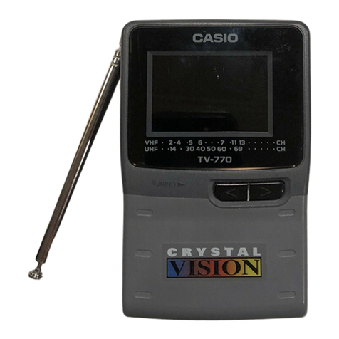
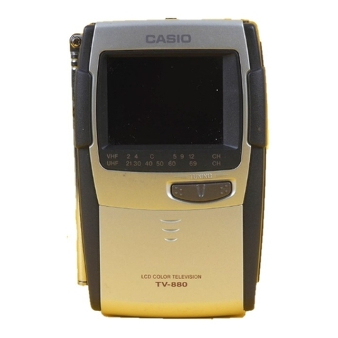
Casio TV-770C Troubleshooting guide

R
(without price)
TV-770C(PAL B / G, H)
TV-770D(PAL I)
TV-770G(PAL M)
TV-770N(PAL B / G, H)
(KX-503)
AUG. 1996
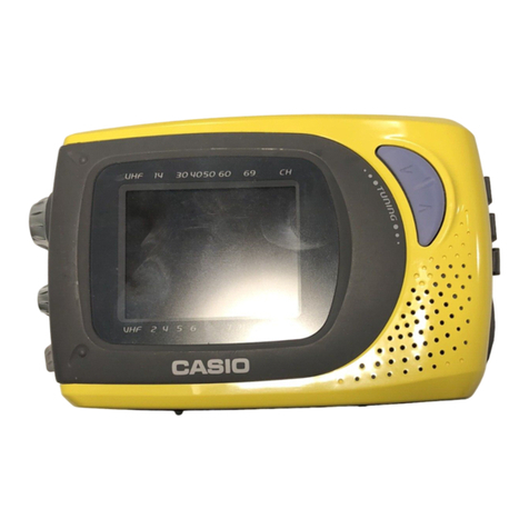
CH 2 4 5 6 7 11 13
CH 14 30 40 50 60 69

CONTENTS
SPECIFICATIONS ......................................................................................... 1
BLOCK DIAGRAM......................................................................................... 2
PRINTED CIRCUIT BOARDS........................................................................ 3
EXPLODED VIEW.......................................................................................... 5
PARTS LIST................................................................................................... 6
IC AND TRANSISTOR LEAD IDENTIFICATION ..........................................9
SCHEMATIC DIAGRAMS............................................................................ 11
WAVEFORMS.............................................................................................. 15

— 1 —
Item Specification
1. Power voltage DC 6.0 V
2. Power consumption Approx. 3.6 W
3. Current consumption Approx. 600 mA
4. Battery life (with alkaline batteries) Approx. 4.0 hours
Batteries : 4 ×LR6 (D) size batteries
5. Power supply Car adaptor : CA-K65
AC adaptor : AD-K64, 65
Earphone jack : 3.5 ø mini
6. Connection terminals External power jack : 6.0 V DC IN
External antenna jack : 3.5 ø mini
7. Screen size 2.3 inches
8. No. of picture element 39,600 (110 ×360) dots
9. Dimensions 127 mm (H) ×81 mm (W) ×35 mm (D)
10. Weight 200 g without batteries
AC adaptor : AD-K64, 65
11. Options Car adaptor : CA-K65
Antenna matching device : AS-35S
SPECIFICATIONS
Model Color System TV System Channel
TV-770C/N PAL B/G, H CCIR VHF: 2 ~ 12 ch UHF: 21 ~ 69 ch
TV-770D PAL –/I UK — UHF: 21 ~ 68 ch
TV-770G PAL M/M US VHF: 2 ~ 13 ch UHF: 14 ~ 69 ch

— 2 —
1— Color tuner: TU200 TEPU5-02/TEPE5-01/TEPB5-05
Selects a desired radio wave and changes it to the video IF signal.
2— Video IF amp.: Q200 2SC4238
Amplifies the video IF signal output from tuner TU200 by 10 times (20 dB).
3— Video det./Sound det./FM det./AFT/AGC: IC200 M51348FP
Eliminatesthe carrierwave inthe videoIF signal,and picksup thevideo signaland thesound IFsignal.
Also, the sound signal is picked up from the sound IF signal by FM detection.
4— Audio amp.: IC600 NJM2070M
Sound amplification.
5— Chroma circuit: IC300 M52045FP
Generates the tricolor (red, green, and blue) from the video signal.
6— Osc./A-D converter/display control/auto-tuning control: IC700 MSM6625-02 GSK-640F
Converts the color signal into a digital signal.
Also, generates the clock pulse for the display and controls the display.
7— Tuning voltage generator: IC500 MSC1169MS-K
Generates the tuning voltage with the tuning pulse output from 6.
8— Display voltage generator: Q800~Q803, Q805, Q806, 2SD601A-R x 4, 2SB709A-R, 2SD1149-S
Generates the display voltages V0 ~ V4 with VEE1 and VCC7 outputs from the power supply.
BLOCK DIAGRAM
Antenna
1TU200 2Q200 3IC200
7
Tuning
Voltage
Generator
VR600
Volume
Control
4IC600 Speaker
IC300
IC700
Common
Driver LCD
Segment
Driver
Chroma
Circuit
Osc.
Display
Control
A-D Converter
Auto-Tuning
Control
5
6
8Q800~Q803, Q805, Q806
VR800 Display
Voltage
Generator
Brightness
Control
VCC2 (3.95 ± 0.02V)
VCC7 (34.2 ~ 41.8V)
VEE1 (–6.1 ~ –7.3V)
IC500
Power
Supply
Audio
Amp.
IF Amp.Tuner
Video
Sound Det.
FM
AFT Circuit
AGC Circuit
Det

— 3 —
PRINTED CIRCUIT BOARDS
TOP VIEWS
Linear
Back Light
R335
R336
R255
R256
R236
C259 C281
R254
R252
R251
C263 C262 R261
C245
R212
R257
R253
R222
R209
C249
R224
C780
R808
R809
R810
C742
C741
C270
C740
R305
R306
C351
R226
C346
R322
C340 R310
R110
R108
C140
R115
R113
R704
C236
R816
R813
R820
C782
R745
R830
C750
D805
D803
Q101
Q110
D155
R738
D707
VR100
VR301
VR300
C330
VR700
R840
L101
R223
VR200
CN710
C305
C309
H300
C208
C210
C207 C202
C205
C606
C603
C806
C808
C700
C800
IC700
C112 C115
C105
C113
C100
C110
D150
SW100
T100
FU100
VR800
VR600
T200
T201
F220
F221
F210
F211
F203
F200
L103
L102
L202
TU200
JK200
JK600
CN700
JK100
D180
T950
C927
C925
CN950
L950

— 4 —
BOTTOM VIEWS
Linear
Back Light
IC200
R331 R330 C350 R116
C348
C347 R326
R325
R247
Q300 R225 C230
R210
OR
BR R645
R706 C282 C345
R307
C335
R707C730
IC300
R260 R258
Q230
R259
C272
R246
C264
C261R241 R239
HD AFT
AUDIO
HP210 VIDEO
COL
ATT
VCC2-3
CP244
BM
SW200
R815
R814 C837
C840
C836
Q801 Q800
Q802 Q803
D800
L710
C770
C841
R800
C830
R803
R827
R833
Q806
Q805
R615
R825 R727
R726
R725
C-SYNC
VEEI
R
G
R733
C760
C756
D705
R730
C758
C761
R719
R718
KDB
B
L705
C751
C755
R700
PD
R709
R710
R711
HP700
C765
VCC2
D152
C153
VCC2-0
C152
Q111
C145
C160
D703
C150
C130
VCC7
GND
R106
R107
C137 C155 D110
D100
R105
TM100
C182
C185
R208
C243
R211
CP330
C233
CP200
R150
C242
C246
BT
BV
BU
C240
VCC1-1 H/L TU
Q200
C238
R205
R202 R207
C550
C237 R203
R201
R204
L200
C239
C232
D500
R503 C530
R550
R500 R501 R502
R607
R606
HP701
C200
C231
R541
C545 C234
R545 C535
R610
R611C250
C635
R641
C630
C265 C642
C641
RF
BS
IC500 IC600
VCC2-8
HP200
IF
CP590
Q950
Q951
R950
R746
C783
CP900
CP990
CP902
SW700
HP906HP905
SW710

— 5 —
10
6
15
16
19 20
18
11
12
13 21
9
5
4
14
1
2
3
LA900
17
8
8
7
7
5
24
23
22
EXPLODED VIEW

PARTS LIST
LINEAR PCB
Item Code No. Parts Name Specification Applicable Q R
Diodes
D100 2390 1176 Chip diode MA152WK-(TX) TV-770 Common 1 C
D110 2315 0166 Chip zener diode MA3047-L(TX) TV-770 Common 1 C
D150 2390 1176 Chip diode MA152WK-(TX) TV-770 Common 1 C
D152 2390 1176 Chip diode MA152WK-(TX) TV-770 Common 1 C
D155 2390 1302 Chip diode MA153A-(TX) TV-770 Common 1 C
D180 2390 1190 Chip diode ERA15-01Y TV-770 Common 1 C
D500 2360 1344 Chip zener diode MA3330-M(TX) TV-770 Common 1 C
D703 2390 0469 Chip diode MA157A-(TX) TV-770 Common 1 C
D705 2390 1358 Variable diode MA329-(TX) TV-770 Common 1 C
D707 2360 1113 Chip zener diode MA3082-M(TX) TV-770 Common 1 C
D800 2360 2919 Chip zener diode MA3056-L(TX) TV-770 Common 1 C
D803 2390 0469 Chip diode MA157A-(TX) TV-770 Common 1 C
D805 2390 1253 Chip diode MA152WA-(TX) TV-770 Common 1 C
Fuse
FU100 3632 0469 Fuse PI-251001(F10) TV-770 Common 1 A
ICs
IC200 2114 1827 Linear IC M51348FP-T1 TV-770 Common 1 C
IC300 2114 3311 Linear IC M52045FP-T1 TV-770 Common 1 C
IC500 2114 0182 Linear IC MSC1169MS-K-620 TV-770 Common 1 C
IC600 2114 2464 Linear IC NJM2070M-T1 TV-770 Common 1 C
IC700 2011 3514 LSI MSM6625-02GSK-640F TV-770 Common 1 C
Jacks
JK100 3501 8281 Jack HEC0811-010010 TV-770 Common 1 B
JK200 3501 5439 Jack HSJ1456-01-210 TV-770 Common 1 C
JK600 3501 5439 Jack HSJ1456-01-210 TV-770 Common 1 C
Transistors
Q101 2230 7011 Chip transistor 2SD601A-R(TX) TV-770 Common 1 B
Q110 2230 7011 Chip transistor 2SD601A-R(TX) TV-770 Common 1 B
Q111 2253 0308 Chip transistor 2SD1119-R(TX) TV-770 Common 1 B
Q200 2252 0707 Chip transistor 2SC4238-(TX) TV-770 Common 1 C
Q300 2210 8026 Chip transistor 2SB709A-R(TX) TV-770 Common 1 C
Q800 2230 7011 Chip transistor 2SD601A-R(TX) TV-770 Common 1 C
Q801 2210 8026 Chip transistor 2SB709A-R(TX) TV-770 Common 1 C
Q802 2230 7011 Chip transistor 2SD601A-R(TX) TV-770 Common 1 C
Q803 2230 7011 Chip transistor 2SD601A-R(TX) TV-770 Common 1 C
Q805 2253 0476 Chip transistor 2SD1149-S(TX) TV-770 Common 1 C
Q806 2230 7011 Chip transistor 2SD601A-R(TX) TV-770 Common 1 C
Switches
SW100 3412 0938 Slide switch ESD-11V231 TV-770C/G/N 1 C
SW100 3412 1134 Slide switch ESD-11V221 TV-770D 1 C
Converter
T100 3065 0672 DC-DC converter LC12U-40 TV-770 Common 1 B
Tuners
TU200 1013 5315Tuner TEPE5-01 TV-770C/N 1 C
TU200 1014 8570Tuner TEPB5-05 TV-770D 1 C
TU200 1013 5511 Tuner TEPU5-02 TV-770G 1 C
Variable resistors
VR600 2765 1708 Volume XV081PV1NB10K3017 TV-770 Common 1 C
VR800 2765 2037 Volume XV081PV1NB20K3017 TV-770 Common 1 C
Notes: Q – Quantity per unit
R – Rank — 6 —
BL PCB
Item Code No. Parts Name Specification Applicable Q R
Lamp
LA900 3851 1918 Fluorescent lamp 3064BB-CA39 TV-770 Common 1 A
Transistors
Q950 2253 0308 Chip transistor 2SD1119-R(TX) TV-770 Common 1 B
Q951 2253 0308 Chip transistor 2SD1119-R(TX) TV-770 Common 1 B
Switches
SW700 3412 1029 Switch SKHHAL TV-770 Common 1 C
SW701 3412 1029 Switch SKHHAL TV-770 Common 1 C
Transformer
T950 3012 1470 Inverter trans NT-07 TV-770 Common 1 B
Notes: Q – Quantity per unit
R – Rank — 7 —

MAIN COMPONENT
Item Code No. Parts Name Specification Applicable Q R
1 6611 3500 Display plate CIM-K503 K440797-6 TV-770C 1 C
1 6611 4570 Display plate DAM-K503 K440928-1 TV-770D 1 C
1 6611 0980 Display plate BXM-K503 K440797-1 TV-770G 1 C
1 6611 3570 Display plate NDM-K503 K440797-7 TV-770N 1 C
2 6611 1010 Adhesive tape A-K503 K440801-1 TV-770 Common 1 X
3 6611 0870 Upper case BXM-K503 K140252-1 TV-770C/G/N 1 X
3 6611 3580 Upper case DAM-K503 K140252-2 TV-770D 1 X
4 6020 7658 Battery spring B1 G513 P408A-1 TV-770 Common 1 X
5 6020 7666 Battery spring B2 G513 P409A-1 TV-770 Common 2 X
6 3831 0854 Speaker 28-8F-03 TV-770 Common 1 C
7 6611 0990 Cushion A-K503 K440802-1 TV-770 Common 2 X
8 6611 1000 Cushion B-K503 K440802-2 TV-770 Common 2 X
9 6611 2290 Tuning button A-K503 K240481-1 TV-770 Common 1 X
10 6611 0890 Battery cover A-K503 K240450-1 TV-770 Common 1 X
11 2725 1218 LCD PSG123CO-TO TV-770 Common 1 C
12 6611 0930 Light diffuser sheet A-K503 K440800-1 TV-770 Common 1 X
13 6611 0900 Reflector case K503 K140261-1 TV-770 Common 1 X
14 6611 2261 BL unit K340625*1 TV-770 Common 1 B
15 6611 0910 Switch knob A-K503 K340575-1 TV-770 Common 1 X
16 6611 0960 Battery spring A-K503 K440798-1 TV-770 Common 1 X
17 6611 0970 Battery spring B-K503 K440799-1 TV-770 Common 1 X
18 6611 3869 Linear PCB ass'y K240530*1 TV-770C/N 1 B
18 6611 4564 Linear PCB ass'y K240543*1 TV-770D 1 B
18 6611 5233 Linear PCB ass'y K240566*1 TV-770G 1 B
19 3851 1470 Rod antenna VR70100GA TV-770 Common 1 B
20 6611 0880 Lower case BXM-K503 K140253-1 TV-770 Common 1 X
21 6611 2300 Stand A-K503 K310518-7 TV-770 Common 1 C
22 6609 1290 Screw A-K610 K412031-1 TV-770 Common 1 C
23 5860 0532 Screw BT3 1.7X9 Bk TV-770 Common 1 C
24 6609 9630 Screw A-K720 K410188-6 TV-770 Common 1 C
Notes: Q – Quantity per unit
R – Rank — 8 —

— 9 —
IC200 IC300
M51348FP-T1 M52045FP
IF AGC OUT 1 24 IF AGC ADJ
IF AGC IN 2 23 SyOUT
RF AGC 3 22 SyIN
AGCDL 4 21 AFTC
VCCv 5 20 LLD
IFIN 6 19 LLD
IFIN 7 18 VIDEO
GNDv 8 17 AFT
VCCs 9 16 SIFOUT
SIFIN 10 15 FMD
FB 11 14 ATT
GNDs 12 13 AUDIO
VIDEO 1 24 VCC
SY IN 2 23 VCXO OUT
ACCF 3 22 NC
SY OUT 4 21 VCXO IN
HDIN 5 20 COLOR
Y CLAMP 6 19 TINT
Y LPF 7 18 KILLER F
Y OUT 8 17 APCF
CONT 9 16 APCREF
R 10 15 KILLER OUT
G 11 14 PIX
B 12 13 GND
IC AND TRANSISTOR LEAD IDENTIFICATION
IC/LSI
Vref 1 16 VCC
U1 2 15 BS
U2 3 14 BT
VL1 4 13 IN
VL2 5 12 OUT
VH1 6 11 TU
VH2 7 10 H/L
GND 8 9 U/V
IC500
MSC1169MS-K-620
NC 1 8 NC
+IN 2 7 VCC
–IN 3 6 OUT
GND 4 5 GND
IC600
NJM2070M-T1

— 10 —
2SB709A
2SC4238 2SD601A
2SD1149-S
C
BE
2SD1119
C
BE
C
IC700
MSM6625-02GSK-640F
TRANSISTORS
AFT
M1
M2
M3
M4
M5
M6
TE6
TE5
TE4
TE3
TE2
TE1
VSS2
CK1
ECB
STB
SCB
CNB
CFB
CDB
SNB
D6
D5
D4
D3
D2
D1
14
13
12
11
10
9
8
7
6
5
4
3
2
1
KDB
KCB
AVB
UHF
VLB
TU
MTB
VDD1
HDB
C-S
PD
OSC2
OSC1
CK2
28
27
26
25
24
23
22
21
20
19
18
17
16
15
AD2
AD1
B
G
R
RLL
VDD2
RHH
M7
M8
M9
M10
PS1
VSS1
43
44
45
46
47
48
49
50
51
52
53
54
55
56
29
30
31
32
33
34
35
36
37
38
39
40
41
42
M11

— 11 —
SCHEMATIC DIAGRAMS
LINEAR (TV-770C/N)
Notes:
1. All resistance values are indicated in "ohms" (k=103ohms, M=106ohms).
2. All capacitance values are indicated in "µF" (p=10-6 µF).
3. All inductance values are indicated in "µH."
Antenna
External Antenna
Jack
Tuner
DC In
Batteries
Audio Amplifier Circuit
Tuning Voltage Generator Circuit
IF Detection Circuit
Earphone
Jack
Speaker
To Back Light
To LCD
Display Controller Circuit
Chroma Circuit
Display Voltage Generator
Circuit
34.2 ~ 41.8 V
-6.1 ~ -7.3 V
3.95 V
Power Switch
Power Supply Circuit
9
10
5
6
7
8
4
3
1
2

— 12 —
LINEAR (TV-770D)
Notes:
1. All resistance values are indicated in "ohms" (k=103ohms, M=106ohms).
2. All capacitance values are indicated in "µF" (p=10-6 µF).
3. All inductance values are indicated in "µH."
Antenna
External Antenna
Jack
Tuner
DC In
Batteries
Audio Amplifier Circuit
Tuning Voltage Generator Circuit
IF Detection Circuit
Earphone
Jack
Speaker
To Back Light
To LCD
Display Controller Circuit
Chroma Circuit
Display Voltage Generator
Circuit
34.2 ~ 41.8 V
-6.1 ~ -7.3 V
3.95 V
Power Switch
Power Supply Circuit
9
10
5
6
7
8
4
3
1
2

— 13 —
LINEAR (TV-770G)
Notes:
1. All resistance values are indicated in "ohms" (k=103ohms, M=106ohms).
2. All capacitance values are indicated in "µF" (p=10-6 µF).
3. All inductance values are indicated in "µH."
Antenna
External Antenna
Jack
Tuner
DC In
Batteries
Audio Amplifier Circuit
Tuning Voltage Generator Circuit
IF Detection Circuit
Earphone
Jack
Speaker
To Back Light
To LCD
Display Controller Circuit
Chroma Circuit
Display Voltage Generator
Circuit
34.2 ~ 41.8 V
-6.1 ~ -7.3 V
3.95 V
Power Switch
Power Supply Circuit
9
10
5
6
7
8
4
3
1
2

— 14 —
To Linear
Notes:
1. All resistance values are indicated in "ohms" (k=103ohms, M=106ohms).
2. All capacitance values are indicated in "µF" (p=10-6 µF).
3. All inductance values are indicated in "µH."
BACK LIGHT

— 15 —
WAVEFORMS
TV-770C/D/N
1Q200 collector 2IC200 pin 19 3IC200 pin 18
4IC300 pin 23 5IC300 pin 12 6IC300 pin 5
7IC300 pin 4 8IC300 pin 1 9IC700 pin16
0IC700 pin 14
64 µs 64 µs 64 µs
0.24 µs 64 µs 64 µs
64 µs 64 µs 130 ns
420 ns
2.0 V
0.8 V
0.1 V
0.8 V
1.8 V
3.0 V
3.0 V
0.8 V
3.0 V
3.0 V

— 16 —
TV-770G
1Q200 collector 2IC200 pin 19 3IC200 pin 18
4IC300 pin 23 5IC300 pin 12 6IC300 pin 5
7IC300 pin 4 8IC300 pin 1 9IC700 pin16
0IC700 pin 14
63.5 µs 63.5 µs 63.5 µs
0.24 µs 63.5 µs 63.5 µs
63.5 µs 63.5 µs 130 ns
420 ns
2.0 V
0.8 V
0.1 V
0.8 V
1.8 V
3.0 V
3.0 V
0.8 V
3.0 V
3.0 V

MA0900461A
This manual suits for next models
3
Table of contents
Other Casio Portable TV manuals

Casio
Casio TV-M430S Troubleshooting guide

Casio
Casio TV-600B Troubleshooting guide

Casio
Casio EV-2500C Troubleshooting guide

Casio
Casio TV-880B Troubleshooting guide

Casio
Casio SY-20B User manual

Casio
Casio FV-600P Troubleshooting guide

Casio
Casio EV-600B Troubleshooting guide

Casio
Casio EV-510C Troubleshooting guide

Casio
Casio TV-600G Troubleshooting guide

Casio
Casio TV-770B Troubleshooting guide