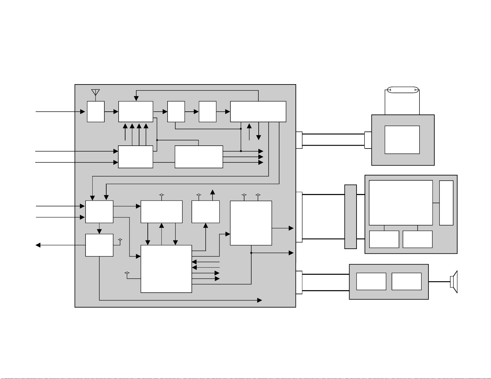
Casio SY-20B User manual

SY-20B (KX-529B)
R
MAY. 2000
SY-20B
(without price)
INDEX

CONTENTS
SPECIFICATIONS ......................................................................................... 1
BLOCK DIAGRAM ........................................................................................ 2
ADJUSTMENT............................................................................................... 3
PRINT CIRCUIT BOARDS ............................................................................ 8
EXPLODED VIEW ....................................................................................... 10
PARTS LIST ................................................................................................ 11
SCHEMATIC DIAGRAMS ........................................................................... 13
DRIP-PROOF PERFORMANCE Q & A....................................................... 15

— 1 —
Item Specification
1. Type LCD Color Television
2. Reception Frequencies: UHF: UHF band CH 14 – CH 69
VHF: VHF band CH 2 – CH 13
3. Display Element: High resolution color liquid crystal display
(Super Twisted Nematic Type)
4. Drive System: Passive matrix system
5. Screen Size: 2.3 inches
6. Backlight: High luminance fluorescent material
7. Antenna: Rod antenna (VHF, UHF)
8. Speaker: 12/16ø inches (28 mm) X1
9. Connection Terminals: External antenna jack (3.5ø mini)
Earphone jack (3.5ø mini)
External power source jack (DC 6V)
Audio/Video input jack (3.5ø mini)
10. Power Supply: 3-way power supply system
Batteries: 4 AA-size dry batteries
AC: AC adaptor AD-K64/AD-K65 (option)
Car battery: Car adaptor CA-K65 (option)
11. Power Consumption: Approx. 3.6 W
12. Ambient Temperature Range: 32°F (0°C) ~ 104°F (40°C)
13. Dimensions: 56/16" (W) X 23/16" (D) X 36/16" (H) inches
136 (W) X 56 (D) X 85 (H) mm
14. Weight: Approx. 9.2 oz 260 g (excluding batteries)
SPECIFICATIONS

— 2 —
BLOCK DIAGRAM
LCD DRIVER (5151)
CH
UPKEY CH
DOWNKEY
LAMP
Vcc1-1,GND
Vcc2-0,GND
V1,V3,V0,V4,VC
CK1,CK2
D1 ~ 6
SNB,STB
CNB2,CDB2,CFB2
EN1,EN2
MODULE
POWER
SUPPLY
MODULE
CONTROLL
SIGNAL
AUDIO2
Vcc7 VEE1
Vcc2
Vcc1-1
AVB
VIDEO2
AUDIO1
VIDEO1
A-MUTE
RGB
HD
C-SYNC
AUDIO1
VIDEO1
H/L
U/V
AFT
Vcc2-8
TU
Vcc7
BT
ANT AGC
Vcc1-1
Vcc2 (4V)
Vcc2 (4.0V)
Vcc7 (40V)
VEE1 (-5V)
AFT
A-MUTE
EAR PHONE
EXTERNAL ANT
BATTERY 1.5V x 4
AC ADAPTOR 6V
EXTERNAL VIDEO
EXTERNAL AUDIO
BV
BS
U/V
BT
CN900
Vcc2-8,GND
KDB,SP+,SP-
CN701
CN950
CN700
Vcc2
TUNER
(TNS-010US)
ANT
JACK PRE
AMP SAW
FILTER VIF/SIF
(M51348FP)
CHROMA
(M52042FP)
TUNING
BT GEN
(BA10358) VOLTAGE
SUPLLY
FOR LCD
DRIVER
AV JACK
LCD
INVERTER
TRANS
LCD
DRIVER
(651)
A/D CONVERTER
CONTROLLER
(OM6006)
AUDIO AMP
(NJM2070M)
POWER SW
BAND SW DC/DC
CONVERTER
TRANS
LCD DRIVER
(651)
L-PCB
BL-PCB
LCM
SW PCB
LCD DRVER(5151)
SP
SP

— 3 —
ADJUSTMENT
1. Vcc2 adjustment, Vcc7, Vee1 voltage check
2. LLD coil adjustment
3. Free running frequency adjustment
4. Contrast adjustment
5. TINT adjustment
Preparations
1. Connect AVB (CP725) to GND.
2. Set SW100 on UHF mode.
Adjustment And Test Point Locations
Top View
BottomView
T 200
VR 300
VR 301
VR 100
CP 102
CP 101 CP 305
CP 238
CP 320 CP 300
CP 740
CP 104
CP 103 CP 729
CP 701

— 4 —
Adjustment procedures
1. Vcc2 adjustment, Vcc7, VEE1 voltage check
•Condition
(1) Signal
No signal
(2) Other conditions
Power supply: Vcc1-1 (CP101) = 5.00 ±0.05 [V]
•Adjustment
Apply 5.00 ±0.05 [V] on Vcc1-1 (CP101).
Adjust VR100 so that Vcc2 (CP102) voltage becomes 4.00 ±0.02 [V].
•Checking
Vcc7 (CP103) = 36.0 ~ 44.0 [V]
VEE1 (CP104) = –4.50 ~ –6.00 [V]
•Block diagram
2. LLD coil adjustment
•Conditions
(1) Signals
Broadcasting system: M/M
Color system: NTSC color bar
(2) Signal level
Input electric field: 40 ±5 dBµ(IF AGC full gain), P/S = 10 dB
(3) Other conditions
US IF (Input electric field: terminated with 75 Ωresistance)
Power supply: Vcc1-1 (CP101) = 5.00 ±0.05 [V]
•Adjustment
Monitor video detection signal (CP238) via a low-pass filter of 100 kHz cutoff frequency and adjust LLD coil
T200 so that its DC level is minimum (waveform’s amplitude is maximum).
•Confirmation
There should be no waveform distortion (erroneous synchronization, etc.), under sensitivity (video detector
output level is abnormally small, etc.).
•Block diagram
VDigital
Voltmeter
L-PCB
Stabilizer
Vcc1-1
Vcc7
Vcc2
VEE1
Vcc1-1
IF signal
L-PCB
Adjust to minimize the DC level.
Oscilloscope
DC IN
Detector OUT
Signal
generator
Stabilizer
Low-Pass Filter

— 5 —
3. Free running frequency adjustment
•Conditions
(1) Signal
No signal (NTSC standard signal should be applied only at synchronous check)
(2) Signal level
Input electric field only at synchronous check: 70 ±3 dBµ(terminated with 75Ωresistance),
P/S = 10 dB
(3) Other conditions
US IF input only at synchronous check (input electric field with 75 Ωtermination).
Connect SYF terminal (CP729) and Vcc2-7 (CP701).
Power supply: Vcc1-1 (CP101) = 5.00 ±0.05 [V]
Room temperature: 20 ±10 [°C]
•Adjustment
Monitoring HDB (CP305) with a frequency counter, adjust VR700 so that the frequency is 15.734 ±0.1 [kHz].
•Caution
(1) Disconnect the wire between SYF terminal. Applying IF signal make sure that synchronization is normal
on the display.
(2) Use input signal pattern conforming CCIR standard.
•Block diagram
L-PCB
SYF
Vcc2-7
HD Frequency
Counter
Vcc1-1
IF signal
Signal
generator
Stabilizer

— 6 —
4. Contrast adjustment
• Conditions
(1) Signals
Broadcasting system: M/M
Color system: NTSC color bar (white 75%)
(2) Signal level
Input electric field: 70 ±3 dBµ(terminated with 75Ωresistance), P/S = 10 dB
(3) Others
US IF input (input electric field should be terminated with 75Ωresistance)
Power supply : Vcc1-1 (CP101) = 5.00 ±0.05 V
•Adjustment
(1) Connect color terminal (CP320) to GND (CP300) so that screen becomes black and white.
(2) Adjust contrast pot VR300 so that the voltage between pedestal level and white level of B signal
(CP740) is 0.80 ±0.05 [V].
•Caution
(1) Make sure that waveforms are not distorted.
(2) Connect COLOR terminal of Chroma IC (M52042FP) to GND.
(3) Monitor the B output signal with an oscilloscope via a low-pass filter (C = 2700 pF, R = 100 Ω).
•Block diagram
L-PCB
Vcc1-1
IF signal
Signal
generator
Stabilizer
B output
Low-pass filter Oscilloscope

— 7 —
5. TINT adjustment
•Condition
(1) Signal
Broadcasting system: M/M
Color system: NTSC color bar (white 75%)
(2) Signal level
Input electric field: 70 ±3 dBµ(75Ωtermination), P/S = 10 dB
(3) Other conditions
US IF input (input electric field should be terminated with 75Ωresistance).
Power suppiy : Vcc1-1 (CP101) = 5.00 ±0.05 [V]
•Adjustment
Observing B output signal (CP740) with an oscilloscope, adjust TINT pot VR301 so that amplitude difference
between two center pulses is 0.1 [V]
•Caution
(1) Do not connect COLOR chroma IC (M52042PP) terminal of to GND.
(2) Monitor B output signal with an oscilloscope via a low-pass filter (C = 2700 pF, R =100 Ω)
•Block diagram
VCC1-1
IF signal
Signal
generator
Stabilizer
L-PCB
B output
Oscilloscope
Low-pass filter

— 8 —
PRINTED CIRCUIT BOARDS
TOP VIEWS
Linear
Connector

— 9 —
BOTTOM VIEWS
Linear
Connector

— 10 —
1
2
45
67
8
910
11
12
13 20
14
18
19
33
34
37
35
36
54
55
39
38 48
50
51 52
53 49
48
47
46
44
43
45
42
41
40
23
24
23
21
22
15 4
17 30
31
16
8
3
32
29
28
27
56
26
25
26
EXPLODED VIEW
TV UNIT

PARTS PRICE LIST
SY-20B
NItem Code No. Parts Name Specification QPrice Code R
N11002 6667 PANEL/DISPLAY K342241-1 1AN X
N21002 2739 TAPE/DOUBLE SIDE K442084-1 1AM X
N31002 3112 PANEL/UPPER K140705-3 1AF X
N41001 8269 SCREW BT3 1.7X5.5Ni 3AA X
N51001 4846 KNOB/VOLUME K341905-1 1AF C
N61001 4845 KNOB/BRIGHT K341906-1 1AF C
N71001 4839 PACKING/KNOB K442072-2 2AA C
N81001 4847 CASING FRAME/KNOB K341910-1 2AA X
N91002 2746 PLATE/RATING K342110-3 1AA X
N10 1002 8375 TAPE/DOUBLE SIDE K442082-4 2AA X
N11 1002 3110 SEAL/AIR ADJUSTMENT K442209-1 1AA X
N12 1001 8268 SCREW BT3 1.7X4.5BK 1AA X
N13 1001 4786 CASING FRAME/SWITCH K341911-1 1AA X
N14 1001 4782 PACKING/SWITCH K442072-3 1AA C
N15 1001 4789 KNOB/SWITCH K341907-1 1AF C
N16 1002 3111 CASE/UPPER K140703-3 1AY X
N17 1001 4795 BUTTON/TUNING K241359-1 1AF C
N18 1001 4771 PACKING/CA K241357-2 1AK C
N19 1001 4765 PACKING/CB K241391-2 1AJ C
N20 1001 4792 PACKING/SPEAKER K341917-1 1AA C
21 3831 1095 SPEAKER 28-8AB-09 1AS B
22 6630 7430 SCREW K440305-1 4AA X
23 6604 3110 SCREW K41310-1 4AA X
N24 1002 3127 PCB ASSY/SWITCH K442206*2 1BB B
N25 1002 2691 CUSHION K442245-1 2AA X
N26 1002 2694 CUSHION K442245-2 2AA -
27 2725 1363 MODULE/LCD CMG23C1-T0 1CX A
N28 1001 4757 PLATE/DIFFUSION K341913-1 1AD X
N29 1002 8372 CASE/REFLECTOR K241353-1 1AF X
30 1002 2458 LAMP/FLUORESCENT 3067(LX)BB-CA52 1AV A
N31 1002 9952 PCB ASSY/BACK LIGHT TK-K140763*2(K529) 1CV B
N32 1002 3121 UNIT/BACK LIGHT K342169*2 1CE X
N33 1002 9950 PCB ASSY/LINEAR TK-K241446*1(K529) 1DQ A
N34 1002 2678 SPRING K442065-1 1AA C
N35 1002 2679 SPRING K442066-1 1AA C
N36 6612 4420 CUSHION K440802-3 1AA X
N37 1002 9949 PLATE/SEALED K342176-1 1AC X
N38 1001 4848 SHAFT/SWITCH K341912-1 1AB X
N39 1002 1366 TERMINAL/ANTENNA K241344-1 1AA C
N40 1001 4834 CASING FRAME/STAND K341909-1 1AC C
41 5860 8820 SCREW BT3 2X6BK 3AA X
N42 1001 4836 PACKING/BATTERY COVER K342056-1 2AA C
N43 1001 4833 STAND K341908-2 1AB B
N44 1001 4835 PACKING/STAND K341916-1 1AA C
N45 1002 2738 ANTENNA/ROD YC-KX-629-M2 1AP A
N46 1001 4840 PACKING/ANTENNA K442072-1 1AA C
N47 1001 4831 CASE/LOWER K140704-2 1AK X
N48 1001 8271 SCREW K442177-1 4AA X
Note : Q - Quantity per unit
R- Rank
- 33 -

NItem Code No. Parts Name Specification QPrice Code R
49 6609 1290 SCREW K412031-1 1AA X
50 1002 2747 LABEL/CAUTIONS K442211-2 1AA X
51 6001 0862 SPRING/BATTERY P408-1 1AB C
52 6001 0871 SPRING/BATTERY P409-1 2AA C
N53 1002 2740 DETECTION SEAL/WET K442210-1 1AB X
N54 1001 4841 PACKING/BATTERY COVER K241358-1 1AC C
N55 1001 4844 COVER/BATTERY K241351-2 1AD B
N56 1002 5291 CASE/SHIELD K241342-1 1AB X
L-PCB
D180 2390 1190 DIODE/CHIP ERA15-01Y 1AA X
F200 3025 1948 FILTER/SAW SAF45MA210Z 1AJ X
F210 3025 1949 FILTER/SIF SFSH4.5MCB 1AB X
F220 3851 2105 DISCRIMINATOR/SERAMIC CDSH4.5MC30K 1AB X
F230 3850 1259 TRAP/SIF TPS4.5MB 1AC X
FU100 1002 3113 FUSE PI-471001(F10) 1AE A
H300 2590 0749 OSCILLATOR HC-49U 1AH X
JK100 3501 8281 JACK/POWER HEC0811-010010 1AD C
JK200 3501 5439 JACK HSJ1456-01-210 1AC C
JK250 3501 3773 JACK/PHONE HSJ6063-01-410 1AH C
JK600 3501 5439 JACK HSJ1456-01-210 1AC C
NSW100 1001 8263 SWITCH/SLIDE SSSS223-11-A 1AD C
T100 3065 0730 CONVERTER/DC-DC LC12U-45 1AE C
NTU210 1002 0377 TUNER TNS-010US-XB 1CI X
VR600 2765 2191 VOLUME RK09K111-10KB-H 1AD C
NVR800 1001 8267 VOLUME RK09K111-20KB-M 1AC C
BL-PCB
NQ950 2253 0287 TRNSISTOR 2SD965-R 1AB X
Q951 2253 0287 TRNSISTOR 2SD965-R 1AB X
T900 3012 1612 TRANS/INVERTER C-8125 1AQ C
SW-PCB
SW801 1001 8262 SWITCH SKHRAB 1AB C
SW802 1001 8262 SWITCH SKHRAB 1AB C
Note : Q - Quantity per unit
R- Rank
- 34 -

— 13 —
SCHEMATIC DIAGRAMS
LINEAR
Antenna
External Antenna
Jack
IF Detection Circuit Audio Amplifier Circuit
Earphone
Jack
Speaker
Tunner
Power Switch
Display Controller Circuit
A/V Jack
AC Jack
Tuning Voltage Generator Circuit
Power Supply Circuit
36.0 ~ 44.0 V
-4.50 ~ -6.00 V
4.00 ±0.02 V
Display Generator Voltage Circuit
Chroma Circuit

— 14 —
BACK LIGHT
CONNECTERSWITCH

— 15 —
DRIP-PROOF PERFORMANCE Q & A
cause1. Can the TV be washed with water?
action1. This TV cannot be washed by applying cold water, hot water, sea water or any other form of moisture.
This naturally is also true for soaps, detergents and other cleaners.
cause2. Is it all right to spray the TV under a shower?
action2. Since operation of the TV is not guaranteed in the case of spraying directly under a shower, it cannot
be sprayed under a shower.
cause3. Is it all right to use the TV in the bath?
action3. The TV cannot be used by submerging in a bathtub or using in locations where it is sprayed directly
from a shower. It can be used under conditions where it is subjected to water droplets dropping from
the ceiling or slight splashing of water droplets from the surroundings. Following use, however, the
TV should be taken out of the bathroom and should not be left in the bathroom.
cause4. Is it all right to use the TV in a pool or at the beach?
action4. The TV cannot be used by submerging in water or when it is subjected to direct spraying of water from
a shower in the same manner as when used in the bath. It can be used in locations where it is
occasionally subjected to splashing of water droplets.
cause5. Is it all right if the TV gets rained on?
action5. It can be used in light rain (such as when the intensity of the rain is less than XX per hour such that
the ground does not become soaked or water accumulates on the ground). Always make sure to wipe
off the TV with a dry cloth when it has become wet after raining.
cause6. Is it all right if the TV gets wet during falling snow?
action6. It can be used provided the amount of falling snow is not to a degree that causes snow to accumulate
on the TV. Always make sure to wipe off the TV with a dry cloth when it has become wet after snowing.
cause7. Is the TV still all right after it has fallen onto a wet surface, wet ground or sandy beach?
action7. Although this TV is ensured to demonstrate drip-proof performance, since its resistance to impact has
not been particularly enhanced, subjecting the TV to strong impacts as a result of being dropped and
so forth can prevent drip-proof performance from being maintained.
cause8. Is it all right to touch the TV with wet hands?
action8. Althoughitisallrighttotouch the exterior of the TV with wet hands, when changing thebatteries,always
make sure that the TV as well as your hands are dry. Opening the battery cover while the product or
your hands are wet can allow water to enter inside the TV possibly causing a malfunction. If water
should happen to enter the battery compartment, remove the batteries and wipe off the batteries and
battery compartment with a dry cloth and cotton swabs before using the TV.
cause9. Is drip-proof performance still maintained even when the antenna is extended?
action9. Drip-proof performance is maintained even when the antenna is extended.

— 16 —
cause10. Are there times when the sound cannot be heard or the volume decreases?
action10. If water is allowed to accumulate in the speaker as a result of subjecting the TV to heavy rain or direct
spraying of water from a shower that exceeds the level of drip-proof performance, the sound may no
longerbe heard or the volume may decrease. When this happens, place the TV with the speaker facing
down to remove the water, carefully wipe off the TV with a dry cloth and allow it to dry before further
use.
cause11. What should be done if the TV is mistakenly dropped into water or subjected to direct spraying from
a shower?
action11. Immediately remove the TV from the water or shower and wipe it off with a dry cloth. Since use of the
TV while there is water present inside can result in the risk of fire or electrical shock, do not attempt
to use the TV and take it to the store where it was purchased or a Casio Techno Service Station.
cause12. What should be done if the battery compartment packing has come off or been damaged?
action12. Since drip-proof performance can no longer be maintained, always take the TV to the store where it
was purchased or a Casio Techno Service Station.
cause13. What should be done if a packing of one of the jacks has come off?
action13. Since drip-proof performance can no longer be maintained, always take the TV to the store where it
was purchased or a Casio Techno Service Station.
cause14. Can the TV be used with an AC adapter or car cigarette lighter adapter?
action14. Yes, it can. However, always make sure to operate the TV with batteries when using around water such
as in the bath or shower. Use of an AC adapter can cause an electrical shock.
cause15. Is the TV subject to condensation of moisture?
action15. Since the TV is not provided with any particular measures against moisture condensation, if moisture
should condense on the TV, carefully wipe it off and allow to dry completely before use.
cause16. What should be done if the screen fogs up?
action16. If the surface of the screen becomes fogged, wipe it off before using the TV. If the inside of the screen
has become fogged, allow the TV to dry completely before use.
cause17. Can the TV become rusted?
action17. Since the battery springs and screws can become rusted, if the TV should become wet, wipe it off and
allow to dry completely.
cause18. What should be done if the inside of the battery cover becomes red?
action18. This is due to the water immersion detection seal having come in contact with water. If this should
happen, always take the TV to the store where it was purchased or a Casio Techno Service Station.
cause19. What is the meaning of the seal inside the stand? Should it be removed? (applicable to white, 3.1K
and yellow 3K)
action19. This seal fulfills an important role in terms of product performance and should never be removed.
cause20. Is drip-proof performance maintained even when the adapter or A/V cord and so forth are connected?
action20. Drip-proof performance cannot be maintained when the connector cover has been removed.
(This applies similarly to the rubber packing of the battery cover.)

CASIO TECHNO CO.,LTD.
Overseas Service Division
Nishi-Shinjuku Kimuraya Bldg. 1F
5-25, Nishi-Shinjuku 7-Chome
Shinjuku-ku, Tokyo 160-0023, Japan
Other manuals for SY-20B
1
This manual suits for next models
1
Table of contents
Other Casio Portable TV manuals

Casio
Casio EV-500B Troubleshooting guide

Casio
Casio TV-600B Troubleshooting guide

Casio
Casio TV-600D User manual

Casio
Casio TV-600G Troubleshooting guide

Casio
Casio TV-880C User manual

Casio
Casio TV-770C Troubleshooting guide

Casio
Casio TV-770B Troubleshooting guide

Casio
Casio EV-600B Troubleshooting guide

Casio
Casio TV-880B Troubleshooting guide

Casio
Casio TV-350C Troubleshooting guide